SlideShare a Scribd company logo
1 of 24
Download to read offline
Ductwork
After studying this chapter, you will be able to:
• Explain operation of the supply and return air duct
systems.
LJ Assemble, join, install, and repair all types of duct.
^1 Tnstail registers, diffusers, and grilles.
^| Insulate and properly support piping.
• Explain why and how to use mastic and fiberglass
membrane.
• Name and describe the use of many types of fittings.
Important Terms
A-coil
bonnet
branch lines
cfm
conventional system
diffusers
downflow furnace
drive cleats
ductboard
extended plenum
fiberglass membrane
forced air
horizontal furnace
insulated flexible duct
mastic
perimeter system
plenum
radial system
register boot
registers
return air
scrim
S-hooks
starting collar
supply air
takeoff
trunk line
U-channels
upflow furnace
vapor barrier
The information contained in this chapter provides
the knowledge needed to working with heating and air
conditioning ductwork. Some sizing information is
presented as simplified "rules of thumb," consistent with
practices in the field, rather than becoming involved
with complex formulas. While the illustrations in this
chapter show typical situations, keep in mind that
adaptation to conform with state and local codes may
be necessary.
28.1 Forced Air Systems
The majority of heating and cooling systems are
classified as "forced air" types. Central heating and
cooling involves the use of one furnace, centrally
located in the structure, that is equipped with a motor
driven fan to blow treated air through a ductwork system
to the living spaces. Basic components of a forced air
system arc a furnace unit, a remote air conditioner
(compressor/condenser unit), ductwork, Figure 28-1,
and registers (outlet devices that direct and usually
control the volume of the airflow). The ductwork
consists of separate "supply air" and "return air"
sections. The supply air section is used to distribute
treated air to living spaces, while the return air section
brings air from the living spaces back to the furnace
unit to be heated or cooled again.
28.1.1 Conventional System
Before the development of forced-air systems,
gravity furnaces were used. These furnaces had to be
located centrally, with short runs of ductwork from the
furnace to the air outlets. All supply air outlets were
located in or near inside walls of rooms. Return air
inlets were generally located in or near the baseboards of
outer walls. For a period of time after they were intro-
duced, forced-air systems were similarly designed, and
many existing houses have this type of system. Such
an arrangement, with inner wall-located outlets and
outer wall-located inlets, is called a conventional
system.
Heating and Cooling Essentials
sufficient and uniform air circulation for maximum
comfort.
Figure 28-1. Installing an air duct system may be a part of
your job in either new construction or remodeling work.
28.1.2 Perimeter System
The perimeter system uses forced air and locates the
supply air outlets in the baseboard along outside walls, or
in floors or ceilings near outer walls Figure 28-2. The
supply air "blankets" the wall against drafts (heating
mode), or radiant heat during the cooling mode. This
air circulates inward to a return air grille located in an
inside wall where it is drawn off and returned to the
furnace for retreatment. The perimeter system provides
28.2 Furnace Classifications
All forced air furnaces are classified according to the
direction of the airflow for Ihe supply air. The upflow and
downflow furnaces are most common, but horizontal-
flow models are necessary for some applications.
28.2.1 Upflow Furnace
The upflow furnace is normally located in a base-
ment or closet, Figure 28-3. The supply air duct system
is attached to the furnace plenum (sometimes called
the bonnet), a sheet metal chamber anchored to the
top of the furnace with sheet metal screws. The air
conditioning evaporator coil is mounted on top of the
furnace, but inside the plenum. The supply air duct is
often insulated to help maintain the temperature of the
treated air. Return air enters the bottom of the furnace.
The blower serves for both heating and air conditioning
mode, but airflow direction remains the same.
28.2.2 Downflow Furnace
A downflow furnace is usually used in a building
having a crawl space under the first floor, or in a mobile
• ; • - : • •
Figure 28-2. The perimeter system uses outlets located along outside walls.
Chapter 28 Ductwork
Flue or vent
Air filter or
electronic air cleaner
Figure 28-3. An upflow furnace has a top-mounted plenum to distribute supply air. Upflow units are typically located in a
basement.
home, Figure 28-4. The air conditioning evaporator
coil is mounted on the bottom of the furnace, inside
the plenum. Supply air travels from the plenum
through ductwork to the living spaces. Return air enters
the top of the furnace. The blower serves for both heating
and air conditioning.
28.2.3 Horizontal Furnace
This horizontal furnace is designed for use in a
crawl space or attic, Figure 28-5. Supply air exits at
one end and return air enters through the other end.
This means the ductwork is located in the crawl space
or in the attic, along with the furnace. These horizontal
furnaces are usually electric, but gas, oil, or heat pump
can be used.
Air Conditioning Evaporators
The A-coil is the most popular type of air condi-
tioning evaporator for residential systems. The slant-
coil and upright-coil types are primarily used for
commercial and industrial systems. Commercial and
many industrial air conditioning systems operate the
same as residential types. The components are simply
bigger (and easier to repair). See Figure 28-6.
28.3 Distribution Systems
There are two types of duct systems commonly used
for supply air distribution. They are the radial system,
which uses strictly round pipe, and the extended plenum
system, which combines round pipes with rectangular
ducts.
28.3.1 Radial Piping System
A radial system is one that uses round pipe
running directly from the plenum to the register hoot
(component that is used to connect the pipe to the
outlet registers). There is a separate run from the
furnace plenum to each register boot. These piping
runs radiate from the furnace plenum, Figure 28-7.
This system is practical where the piping runs are
located in an attic or crawl space. The radial system is
most economical and easiest to install, but is not prac-
tical if the furnace cannot be centrally located. Any
Heating and Cooling Essentials
Extended
plenum
Figure 28-4. In a mobile home, or a building with a crawl space instead of a basement the downflow furnace is commonly
installed. The plenum is below the unit.
'Air filter Flue
Figure 28-5. A horizontal furnace is usually located in an attic or a crawl space.
Chapter 28 Ductwork
A-coil
Supply air ^ Supply air
Liquid
line
Suction
Slant coil
Supply
air
Liquid
tine
Condensate
catch pan
Equalizer
Condensate
drain
Return air
Suction
Return air
Upright coil
Liquid
line
Suction
Supply
air
Condensate
catch pan
Condensate
drain
Condensate
catch pan
Condensate
drain
Figure 28-6. The three types of air conditioning evaporators. In residential installations, the A-coii type is most
commonly used.
building that is odd-shaped or long cannot use the plenum is extended with rectangular duct, and all
radial system.
28.3.2 Extended Plenum System
An extended plenum system, Figure 28-8,
combines rectangular duct with round pipes. The furnace
round pipes branch out at right angles from the
extended plenum. This permits short lengths of round
pipe to reach the registers. For a neat appearance, the
round pipes are normally installed in the spaces between
the flooring joists. It is necessary to cut a hole and add
a register boot at the end of each run.
Stack pipe
Register boot
Round pipe Takeoff or start collar
Figure 28-7. The radial piping system uses round pipes running straight to the register boots. In this exampie, the stack pipe
nil- +/-t on nnnar flr^nr fnr fi'mtrihl itiDn
.-..-.-., *^
Heating and Cooling Essentials
Branch piping Register
boot
Plenum
Furnace
Side takeoff
Extended
plenum
Figure 28-8. Round branch piping extends outward from an extended pienum formed with rectangular duct.
28.4 Distribution System Components-^
The "supply air" distribution system includes the
plenum, the main trunk line, and all the branches serving
different living spaces. Each branch terminates in a
register that directs and usually controls the volume of
the airflow. Another system of air duct serves to return
air from the living spaces for heating or cooling. This
system is called "return air," and includes another
main trunk line and all its branches.
28.4.1 Plenum (Bonnet)
The first fitting to be installed on any system is the
plenum, sometimes called a bonnet. Figure 28-9. It is
usually made of 30-gauge, galvanized sheet metal,
forming a chamber that is attached to the furnace
outlet, Figure 28-9A. The plenum functions as an air-
mixing chamber before sending the air to the living
spaces. It also provides the necessary surface for
attaching takeoffs and starting collars. The cooling
Plenum parts
Plenum kit
with evaporator
A B C
Figure 28-9. A plenum can be fabricated in the field (A, B) or it may be assembled from a factory kit (C).
Chapter 28 Ductwork
evaporator is located inside the plenum, Figure 28-9B,
and the supply air duct attaches to the plenum. The
furnace manufacturer offers a plenum kit along with
the necessary evaporator. For adding air conditioning to
a previously installed furnace, some sheet metal work
may be required. After all parts are assembled and
screwed together, the seams must be anchored with
.sheet metal screws and sealed with mastic (a nontoxic
adhesive material used for permanently sealing joints
and seams). See Figure 28-9C.
Ductboard made from compressed fiberglass is
becoming increasingly popular for plenums and
rectangular duct. Ductboard is inexpensive, easy to
work with, cuts with a knife, and is already insulated.
Applying insulation by hand to metal ducts is often
necessary, but is time-consuming and costly. See
Figure 28-10.
Ductboard
Insulation
Mastic
28.4.2 Round Metal Pipe
Round pipe can be used as a main trunk line or a
branch line, in both supply air and return air situations.
Round metal pipe has the most efficient charac tens tics,
and is commonly used. For heating only, the round pipe
supplying air to a register outlet need only be 6" in
diameter. For air conditioning, or combined heating and
cooling, the pipe should be 8"in diameter. Additional
6"- runs are often used to obtain required capacity.
Standard round pipe comes in 30-gauge, 3"-14" in
diameter, and in 2', 3', 5', and 10' lengths. All round
pipe is factory crimped on one end for easy insertion
into another length of pipe, See Figure 28-11.
Seam
Figure 28-10. A plenum can be fabricated from ductboard,
which is less expensive than installing insulation by hand on
a metal plenum.
Crimped
end
Figure 28-11. Hound pipe for branch lines can easily be
snapped together at the seam. The crimped area at one end
allows the pipe to be slipped inside the next section of pipe,
forming a joint
28.4.3 Rectangular Duct
Rectangular duct is 30-gaugc, galvanized sheet
metal, and mainly used as a trunk line, or "extended
plenum." Rectangular duct is widely used in the north-
eastern and northwestern parts of the United States. It
is used as a spacesaver and can be easily routed in
overhead space between floor joists, or in an attic.
Branch lines consisting of round pipe come off the
extended plenum to transport air to a register. A branch
line begins with a starting collar or takeoff installed on
the extended plenum, (main trunk line). The end of the
extended plenum must be blocked wilh an end cap that
is anchored with sheet metal screws and sealed with
mastic. See Figure 28-12.
'Takeoff
Rectangular duct
Plenum
End cap
Figure 28-12. An extended plenum, formed from rectangular duct, has a takeoff fitting at one end and a cap at the other.
Heating and Cooling Essentials
28.4.4 Insulated Flexible Duct
As shown in Figure 28-13, insulated flexible duct
consists of several layers, each with a specific func-
tion. The core is usually two plies of polyester film
used to encapsulate the galvanized steel wire helix.
The purpose of the wire helix is to help flexible duct
keep its shape. The insulation is a fiberglass blanket,
varying in thickness, depending on the R-valuc. Many
states have adopted energy codes for flexible duct that
require certain R-values for code approval. A basic
requirement is an R-value of 4.3, but Florida requires
an R-6, and Washington and Oregon require R-8.
Scrim is a high-tensile-strength, fiberglass mesh that
provides more protection protect the insulation and
inner core. The vapor barrier is a plastic jacket or
sleeve that encloses the product.
Major Duct Types
CORE
shields fiberglass
Vapor barrier
HELIX
steel wire coil
SCRIM
protects insulation
Figure 28-13. This cutaway view shows the construction of
a typical insulated flexible duct.
Round metal
pipe
Insulated
flexible
duct
Rectangular
duct
Pros
1. Excellent airflow
characteristics
2. Longer-lasting
than flexible duct
1. Pre-insulated
2. Ease of
installation
3. Reduced labor
costs
4. Eliminates some
fittings
1. Spacesaver; can
use space
between floor
studs
2. Longer-lasting
than flexible duct
Cons
1. If required,
insulation must
be installed
1. Not as long-lasting
as metal duct
2. Some reduction
in airflow
3. Must be fully
extended (cannot
make sharp
bends)
1. If required,
insulation must
be installed
Figure 28-14. Advantages and disadvantages of three types
of air duct.
28.5.1 Sizing the Extended Plenum
The extended plenum is sized according to the
number and sizes of round pipe it serves. It is easier to
have an extended plenum the same width throughout,
therefore, all the pipes are counted and the entire
extended plenum is sized accordingly. Rectangular duct
Comparison of ductwork types
Various types of ductwork are available for use in a
heating and air conditioning system. Because they
were all designed for a particular application, they
have different strengths and weaknesses. Figure 28-14
is a list of some pros and cons of the major duct types.
28.5 System Efficiency #
An efficient residential heating/cooling system will
move air at the proper velocity and quantity to each
room, and enter that room at the proper location.
Velocity is important: air that is moving too fast creates
uncomfortable drafts and makes more noise as it comes
through the system. Air moving too slowly will not have
enough speed to be thrown across the room or up the
wall. Sec Figure 28-15.
Rules of Thumb
Air should travel from the furnace/air
conditioner throughout the system at an
average velocity of about 700 ft./min.
On average, most system resistance to airflow
is approximately 0.08 (0.075) static pressure
(0.10 Supply air, 0.05 return air).
With an air velocity of about 700 ft/min,, air
conditioners are designed to move 400 CFM
PER TON, and furnaces at 12 CFM/1000Btu.
In general, 1 CFM of air is required to heat or
cool 1 or 1-1/4 sq. ft. of floor area.
Figure 28-15. Regular use of these rules of thumb will help
you solve forced-air system problems.
Chapter 28 Ductwork
used for extended plenums is 30-gauge, galvanized
sheet metal, 8" deep, 60" long, and comes in standard
widths of 10", 14", 18", 24" and 28". One of these
standard sizes should provide the needed capacity, but
any length of duct can be cut to a shorter length.
28.5.2 Rule of Thumb for Determining
Plenum Size
To determine the width required for an extended
plenum, counl the number of round pipes it will serve,
Figure 28-16. For 6" round pipes, multiply this number
by 2, then add 2 — the total is the required duct width
in inches. For 8* round pipes, multiply by 3, then add 2.
If the desired size is not available, choose the next
larger size. See
EXAMPLES:
A duct serving four 6" round pipes will have a
widthof4x2 = 8 + 2 = 10.
A duct serving five 8" round pipes should have a
width of 5 X 3 = 15 + 2 = 17. Since rectangular
duct is not available in a 17" width, use the next
larger standard size, which is 18".
28.5.3 Rule of Thumb for Determining Size
of Branch Lines
1. Determine square footage of the room.
Length of room, times width of room, equals
square footage.
10'X 12'= 120 sq.ft.
2. Determine cfm of air needed to supply the room,
cfm means "Cubic Feet per Minute" and defines
the amount of air flowing.
One cfm of air is required to heat or cool
1.00-1.25 sq. ft. of floor area.
EXAMPLE:
A 120 sq. ft. room will require between 96 and
120 cfm.
6" pipes
Figure 28-16. The number and size of round pipe branch
lines determines the width of the extended plenum.
3. Select pipe(s) size according to cfm needed.
How much air can a given diameter of pipe carry?
A 120 sq. ft. room requiring 96-120 cfm will need
one 6" pipe (110 cfm), or use a combination to
total about 96-120 cfm.
120 -f 1.00= 120 120- 1.25 = 96
Square footage
Room size
cfm required
64
(8X8)
51-64
80
(8X10)
64-80
100
(10 X 10)
80-100
120
(10 X 12)
96-120
150
(10 X 15)
120-150
200
(12.5 X 16}
160-200
256
(16X 16)
205-256
Heating and Cooling Essentials
Pipe size
(diameter
4"
5"
6"
7"
8"
10"
12"
14"
Avg. cfm @
Static pressure
30 cfm
65 cfm
110 cfm
160 cfm
230 cfm
410 cfm
680 cfm
1000 cfm
Straight cut Right cut Left cut
28.5.4 Provide Adequate Airflow
A furnace located in a small utility room or closet
may not receive a sufficient amount of air for proper
combustion. If the furnace room is closed off, provide
an adequate air supply by installing two grilles in a
door or wall facing a well-ventilated area, Figure 28-17.
One grille should be in a high-wall position or at top
of the door, and the other should be in a low position.
28.6 Ductwork Tools
Persons working with air duct commonly use the
special hand tools shown in Figure 28-18. The name
of the tool describes its use. Other basic hand tools are
also needed. These might include a trouble light,
Return air
grilles
Plenum
Note: Aviation snips are used for cutting
holes in sheet metal. Never use them to cut wire.
1"X 30" tape
Ball pein hammer
Figure 28-17. Two grilles in a closet door provide sufficient
airflow for furnace operation and return air.
Hand crimper
Figure 28-18. Hand tools often are named according to the
job they perform.
Chapter 28 Ductwork
battery operated drill, chisel, gloves, lineman's pliers,
diagonal cutters, and longnose pliers. NOTE:
Aviation snips are used for cutting openings in
sheet metal. Never use them to cut wire.
28.7 How to Lay out a Duct System —#
The heating and cooling units should be matched to
the square footage of the building's floor space. In addi-
tion, they should be able to distribute a set quantity of air
(measured in cubic feet per minute, or cfm) to the
living area through the duct system, Figure 28-19. A
living space of 1200 sq. ft. is matched up with a
100,000 Btu furnace and a 3-ton air conditioner,
Figure 28-19A. Come off the plenum with one or two
main trunk lines having a total capacity of 1200 cfm,
running toward the living areas. Figure 28-19B.
EXAMPLES:
Two 12" round duct main trunks @ 620 cfm each
= 1200 cfm
Three 10" round duct main trunks @ 400 cfm
each = 1200 cfm
With the main trunk lines installed, begin branching
from the mains with smaller lines running to the various
rooms. Always keep a constant rate of airflow (cfm) to
the various rooms. A branch line must properly reduce
in size to maintain a constant airflow from the trunk
line. A vclocimeter or anemometer. Figure 28-20, is
often used to check and correct airflow problems. Such
meters can read velocity (speed), cfm (flow), and
temperature.
28.8 Installing Startinj
and Takeoffs -
Collars
Starting collars and takeoffs are installed on the
plenum to begin a "run." A starting collar is used with
round duct, while a takeoffis used with rectangular duct.
28.8.1 Starting Collars for Round Duct
It is best to mount the starting collar on the side of
the plenum, 6" below the top, to ensure proper mixing
of the air. Never install a collar on top of the plenum.
To install a starting collar, first mark the proper size
opening with a pencil or metal scribe, Figure 28-21.
Next, pierce the metal surface with a sharp tool and
use snips to cut the opening. Then, insert the collar
into the opening and fold the tabs down inside the
plenum. Finally, secure the collar with three sheet
metal screws and seal it with mastic.
Sq. Ft. of
Floor Area
400
800
1,200
1,600
2,000
Furnace
BTU's
33,000
67,000
100,000
133,000
167,000
Air Conditioner
Tonnage
1 Ton
2 Ton
3 Ton
4 Ton
5 Ton
CFM of
Air Movement
400
800
1,200
1,600
2,000
Dimensions
4" Round
5" Round
6" Round
21
/4"X 10"
21
/4"X12"
31
/4" X 10"
3V4"X 12"
7" Round
31
/4"X14"
8" Round
8" X 8"
9" Round
10" Round
12" X 8"
12" Round
16"X8"
14" Round
16" Round
Approx. CFM
30
60
100
60
70
100
120
150
140
200
260
290
400
440
620
660
930
1300
Sq. In.
12.57"
19.64"
28.27"
23.00"
27.00"
33.00"
39.00"
38.48"
46.00"
50.27"
64.00"
63.62"
78.54"
96.00"
113.09"
128.00"
153.93"
201.06"
B
Figure 28-19. A—Heating and cooling units
floor area. B—Approximate cfm of airflow (at
700 ft./min.) for different-size ducts.
matched to
a velocity of
28.8.2 Takeoff for Rectangular Duct
Manufactured takeoffs arc available in many sizes,
such as 8"x 8", I2"x 8", 14"x 8", or 16"x 8", and
mount easily on any side of the plenum. It is best to
mount the takeoff 6" below the top of the plenum to
ensure proper mixing of the air, Figure 28-22. When
the furnace is located at one end of the house, the
extended plenum may run to the opposite end. When
the furnace is located at the center of the house, two
takeoffs are used to provide an extended plenum on
each side of the furnace.
Heating and Cooling Essentials
Takeoff
Figure 28-20. Anemometer is used to obtain airspeed, cfm,
and temperature. (Courtesy of Sperry Instruments, Inc.)
A
B
Figure 28-21. A—Mark and cut the opening for the starting
collar on plenum. B—Insert the collar and bend tabs over.
Secure the collar with three metal screws and seal with
mastic.
Figure 28-22. Top of the takeoff should be located 6" below
the top of the plenum.
To install the takeoff, first mark off the proper size
opening. Next, pieree the metal surface using a drill or
sharp tool and cut the opening with snips. Then, insert
the takeoff into the opening, and fold the tabs down
inside. Finally, secure the takeoff with three sheet
metal screws and seal it with mastic.
28.9 Working with Round Metal Pipe-*
Standard round pipe is made of 30-gauge, galva-
nized metal. Figure 28-23. Round pipe is usually
shipped nested, with the seams open, Figure 28-23A.
Fittings are usually shipped preformed and ready to
install. Each pipe length has an easily connected snap-
lock seam. Round the pipe with your hands until the
two seam edges meet. Insert the tongue on one seam
edge into the groove on the other seam edge. Start at
one end of the pipe and work down the seam toward
the other end until the entire scam is snapped shut,
Figure 28-23B.
B
End View of
Locked Seam
Figure 28-23. Round metal pipe. A—Nested pipe lengths
with open seams. B—Self-locking seam snaps together
when compressed or squeezed with normal hand pressure.
Chapter 28 Ductwork
28.9.1 Joining Pipe Lengths
Each pipe length has a plain end and a crimped
end. Lengths are joined by sliding the plain end of one
length over the crimped end of another length. Line up
seams for best appearance and push lengths together for
a tight joint. Fittings are made similarly. The crimped
ends always point in the direction of airflow. Secure
each joint with three drive screws evenly spaced around
the joint and seal with mastic. See Figure 28-24.
Airflow Bead Crimped end
Plain end
/
Magnetic screw
holder
Drive screw cuts
own hole
Figure 28-24. Joining pipe lengths. Making connections with
round pipe should be step-by-step. A—Each length has a
crimped end and a plain end. B—The crimped end slides into
the plain end of the next pipe until seated against the bead.
C—Three drive screws should be used to secure each joint.
Temporary wire supports are often used to hold pipe steady
while connections are being made.
28.9.2 Cutting Round Pipe
The last length of duct in a run usually must be cut,
Figure 28-25. Do not snap the seam together until
after the cut is made. Hold the last piece of unformed
pipe in place and mark where it is to be cut. Your
cutting mark should be on the plain (not crimped) end.
Be sure to allow enough extra length for the cut end to
slip over the crimped end of the preceding piece, up to
the bead. Draw a straight cutting line across the pipe,
then make the cut with tin snips. When you make the
cut, the tin snips will squeeze the snap-lock seam edge
closed. Before you can form the pipe, you will have to
pry the seam open again, using a screwdriver.
If you need to cut a piece of pipe that is already
formed, use a hacksaw. Make a continuous line around
the pipe to follow while cutting. Support the round
pipe between two wood blocks or other flat pieces,
then saw with smooth, even strokes, beginning at the
seam. Because of the hacksaw frame, you will only be
able to saw part way through the pipe. You will need to
rotate pipe and start again with saw on top. Continue
in this manner until the cut is complete.
28.9.3 Adjustable Elbows
Adjustable elbows can be conformed to the desired
angle. A 90°adjustable elbow can be twisted to form any
angle from 0°-90°, Figure 28-26. A 45° adjustable
elbow is also available. Insert the crimped end to move
with the direction of airflow. Install the elbow and
secure the joint with sheet metal screws, then seal it
with fiberglass tape and mastic. Do not use ordinary
duct tape.
28.9.4 Sealing Collars
Fiberglass reinforcing membrane will wrinkle
when it is wrapped around a joint between round and
rectangular ducts. To make the membrane material lie
Cutting line
Last piece of pipe
A B
Figure 28-25. In a branch run, the last piece must usually be cut to size. A—Mark the cut with a pencil or scratch awl on the
Heating and Cooling Essentials
Adjustable Elbow
90°
45°
Figure 28-26. Adjustable elbows are convenient for making
all types of turns. They are available in all round duct sizes.
flat, use a utility knife, to make a series of slices about
every two inches along its edge. When the material is
wrapped around the round duct, the tabs will fan out
and lie flat against the rectangular duct, Figure 28-27.
28.10 Extended Plenum System #
Begin with the takeoff fitting in the plenum, and
work outward. When a branch pipe comes off the top
Figure 28-27. After securing the collar with sheet metal
screws, seal the collar with membrane and mastic. This
prevents leaks due to vibration. Cutting slits in the
membrane will help it lie flat.
of the extended plenum, install the starting collar before
assembling the rectangulai" duct. Side staiting collars or
takeoffs can be installed in the extended plenum after
the run is completed. See Figure 28-28.
Support the duct at intervals with hangers or straps.
Be .sure to keep ducts at least one inch from joists and
other combustible materials. Close the end with an end
cap. After completing the extended plenum with
starting collars or takeoff fittings attached, install
branch runs to connect with outlets, insulate all supply
ducts and pipes that are located in unheated areas.
28.10.1 Working with Rectangular Duct
Most rectangular duct is made of 28-gauge galva-
nized sheet metal in 4' lengths. Each duct length is
made up of two half sections, as shown in Figure 28-29.
Branch piping
Plenum
Figure 28-28. An extended plenum system uses side takeoff fittings to connect branch lines. A centrally located furnace may
have two extended plenums, one on each side.
Chapter 28 Ductwork
A B C
Figure 28-29. How to assemble rectangular duct. A—Match
the ends of the two half sections. B—Start the edge channels.
C—Slide the two sections together.
To form a length, place the two half sections on the
floor with the "S-hook" ends up. Pick up one piece and
engage its edge channels with the channels on the other
piece, then slide the two together.
After assembling a section of duct, hammer each
channel snug for a tight fit. This can be done as shown
in Figure 28-30. Hang the assembled duct over a sturdy
board suspended between two sawhorses so the seam
lies flat on the board edge. Use a ball pcin hammer to
tighten the seam.
Rectangular duct is joined with "S-hooks" and
drive cleats, Figure 28-31. One end of each section
has formed S-hooks on the long edges and "U" channels
for the drive cleats on the short edges. The other end
has plain long edges, with U-channels on the short
edges. Join pieces by inserting a plain end into the
S-hooks of the next piece, as shown in Figure 28-31B.
Slide drive cleats through the U-channcls to lock the
pieces together, Figure 28-31C. Drive cleats are 10"
long and used on 8" rectangular duct. When the drive
cleats arc in place, bend ends down over duct to
complete and secure the joint. Seal the joint with mastic.
Where a shorter length is required, cut the two
pieces before forming the duct. Always cut the plain
end, not the end with the S-hook connection. Measure
carefully, then cut both pieces to the same length with
tin snips, Figure 28-32. After cutting, use a sturdy
screwdriver to pry the edge channels to their original
form. Cut back the corners of the new end and use a
hand scamcr to form a new U-channel on the short
edge of each piece.
Figure 28-30. Use a ball pein hammer on each seam for a
tight fit.
S-hook
B
U-channel
Figure 28-31. Joining rectangular duct, using S-hooks and
drive cleats.
Figure 28-32. Measure carefully, then use snips to cut duct
pieces to size.
28.10.2 Cutting Openings
To begin branch pipe runs, openings must be cut in
the plenum. Figure 28-33. These openings may be
rectangular or round, depending upon whether a
Heating and Cooling Essentials
Figure 28-33. Installing a top-mounted takeoff. A—Draw the outline for the opening. B—Punch a hole to use when starting
the cutting snips. C—Cut around the outline.
starting collar or takeoff is used. Make a template of
the opening required and draw its outline accurately on
the metal to be cut, Figure 28-33A. Punch a hole through
the sheet metal within limits of the opening, using a
hammer and chisel or similar tool, Figure 28-33B. Insert
aviator snips and cut to the outline, then around the
outline until the opening is complete, Figure 28-33C.
When a branch pipe will be run from the top of an
extended plenum, the opening must be cut and the
takeoff or starting collar installed before the plenum is
fastened in place. Openings on the sides of the plenum
can be made at any time.
28.10.3 Rectangular 90° Elbows
Rectangular elbows are not adjustable, but are
available in 90° "long-way" or 90° "short-way" forms,
Figure 28-34. They are also available in 45° configu-
rations. A long-way elbow changes the direction of the
Long-way
Short-way
long dimension, and the short-way elbow changes the
direction of the short dimension. To form any smaller
angle needed, 45° and 90° rectangular elbows can be
cut.
28.11 Duct Support
All duct should be run in a straight line and
supported at regular intervals — typically, 2'-5' — to
prevent any sags. The best support material is woven
polypropylene strap that comes in various widths. It is
sometimes called "webbing strap" and is wide enough
so it won't bite into flex duct. Perforated metal strap is
a second choice, with steel wire being least desirable.
Steel wire is still often used to support round pipe for
branch runs. The wire should be wrapped once around
the pipe before anchoring to a joist. See Figure 28-35.
Window
Perforated
pipe strap
Steel wire
Figure 28-34. Rectangular elbows are made in two vari-
eties: long-way and short-way. They are not adjustable.
Figure 28-35. Three methods of duct support include woven
polypropylene strapping, perforated pipestrap, and wire.
Chapter 28 Ductwork
Keep pipes at least one inch from joists and other
combustible material. To prevent heat loss, metal duct is
often wrapped with insulation, Figure 28-36. If insu-
lating material is appl ied after the duct is already in place,
the insulation will have to be slit or stripped to get
around the supporting strap or wire. This opening must
be rescalcd to maintain insulating effectiveness.
Insulation Pipe
Roof joist
Strapping
Insulation Strapping
Figure 28-36. Duct is often located in the basement and
hidden between floor joists. When located in the attic, it is
hung with strapping attached to roof joists. Insulation is often
wrapped around the duct to prevent heat loss.
28.12 Working with Insulated
Flexible Duct -
Insulated flexible duct can be used for main trunk
line runs; it also can be used as branching duct,
Figure 28-37. This type of duct is available in a variety
of sizes, insulation thickness, and specifications,
Figure 28-38. Check local building codes for the exact
R-value required in your area. To prevent reduced
airflow, insulated flexible duct must be fully extended
when installed. Avoid any abrupt turns. When a sharp
turn is necessary, cut the flex duct at the turn and
install a 90-degree elbow of the same diameter. Do not
use wire to support flexible duct. Instead, use a wide
fabric strapping material and anchor it to wood
framing with staples.
28.12.1 Making Connections
Making connections with insulated flexible pipe is
not difficult, but must be performed properly to obtain
Figure 28-37. Insulated flexible duct used for a branch line
in a commercial application. The diffuser is sized to drop into
the suspended ceiling grid.
Figure 28-38. Different sizes and insulation thicknesses are
available in insulated flexible duct.
correct airflow and prevent leaks. Figure 28-39 shows
the connection procedure step-by-step.
28.13 Wall Stack
Wall stacks, Figure 28-40, transport air vertically,
from floor to floor. In residential applications, stacks
carry air to high-wall or second-floor registers from a
basement or crawl space. They can also be used to
carry air to baseboard or low-wall registers from attic
piping.
28.13.1 Installing Wall Stack
If possible, work from the basement. As each
section is attached, push the stack up into the stud
space and attach the next section, Figure 28-41.
Continue until the top of the stack reaches the register
box or lilting to which it will connect. Reduce the
Heating and Cooling Essentials
4" metal sleeve
D
Figure 28-39. Connecting lengths of insulated flexible duct. A—Cut completely around and through duct with knife or scissors.
Cut wire helix with heavy-duty snips or side cutters. B—Peel back the jacket and insulation from core. Butt two cores together
on a standard 4" metal sleeve . C—Tape core together with at least two wraps of duct tape. Secure with two approved clamps.
D—Pull jacket and insulation back over cores. Tape jackets together with two wraps of tape, then mastic sealant.
28.14 Registers and Diffusers
Figure 28-40. Rectangular duct is used to provide vertical
passages (wall stacks) that carry treated air from floor-to-
floor of a building. This stack is being fabricated for use in an
office building. Note: The worker should be wearing safety
glasses.
length of last section as required. When stack must be
lowered from above, enlarge openings as necessary
and lower stack into the stud space as it is assembled
section by section.
To join two sections of stack (or "riser") duct
together, "S" cleats can be used to secure the long
sides of the duct. Sheet metal screws should be applied
on the shorter sides of the ducting, and if needed, can be
used on the longer dimension. The seams are then sealed
with mastic. The same care should be taken when
connecting with the stack heads or boots, Figure 28-42.
The final fitting in the duct system used to move air
to its destination is the register box, or "boot." Due to
the numerous locations and difficult areas registers
must fit, boots are available in a variety of shapes and
sizes, Figure 28-43. Supply air is released into a room
Wall studs
Drywall
Floor joists Floor
Figure 28-41. In residential installations, wall stack is gener-
ally pushed up into the wall from the basement. When
cutting openings for a stack, use a flashlight and mirror to
check for obstructions between studs.
Chapter 28 Ductwork
31
/4"
21
/4"
Wall
stack
Boot Boot
8" pipe 6" pipe
Figure 28-42. Wall stack duct is designed to fit between the
studs inside a wall. Different sizes include 2-1/4" or 3-1/4"
deep by 10", 12" or 14" wide. Standard length of a stack
section is 24".
through registers or diffusers. Both have dampers or
vanes for controlling the amount of air, but diffusers
also have adjustable vanes for controlling the direction
of discharged air. For most effective air movement,
registers and diffusers are located in the baseboard on
an outside wall, or in the floor near the baseboard.
28.14.1 Locating a Floor Diffuser
Locate the diffuser near an outside wall, but at
sufficient distance from the wall to clear draperies or
other obstructions. Draw an outline of the opening
required, then drill a hole in the center of the planned
opening. Measure from the hole to the sides of the
opening, then go into the basement or crawl space and
find the hole position from below. Measure the same
distance from the hole to be sure it will clear floor
joists or other obstructions. If not, the opening must be
shifted. See Figure 28-44.
28.14.2 Installing a Floor Diffuser
A typical one-piece diffuser fits into a 12" x 4"
rectangular opening in a register boot. Alter locating
the proper position, cut a hole in the floor just large
enough for the boot to lit snugly. The metal edges of
the boot should be level with the floor. Secure the boot
in position by nailing it to the floorboards. Insert the
diffuser into the boot and anchor it with screws at each
end. See Figure 28-45.
Floor Wall diffuser Floor
Figure 28-43. Placement of supply registers or diffusers is important to ensure a pleasant room temperature. A variety of
shapes and sizes are available to meet varying requirements.
Heating and Cooling Essentials
Figure 28-44. Preparing to cut a floor diffuser opening. A—Measure and trace the opening for the diffuser. B—Drill a centered
hole through floor. C—Check clearances from below.
Figure 28-45. installing a floor diffuser. A—Cut along the outline with a jigsaw, circular, or reciprocating saw. B—Secure the
register box (boot) to floor with nails. C—Install the floor diffuser into boot opening and secure it with screws.
28.15 Return Air System - --#
In houses where air can easily circulate to one loca-
tion, a central return air grille is adequate. In two-story
homes or long ranch designs, a more efficient, yet
more expensive system routes air through separate
piping from individual rooms back to the furnace for
retreatment. The system filter or electronic air cleaner
is normally installed where the return air duct attaches
to the furnace, Figure 28-46.
A disposable filter is usually made of fiberglass
within a cardboard frame, Figure 28-47. These filters
should be replaced at regular intervals to avoid
restricted airflow. An arrow printed on the filter frame
.shows direction of airflow.
28.15.1 Return Air Grilles
Return air grilles are nonadj us table, and are not
equipped with dampers. They should permit unre-
stricted ffow of return air back to the furnace. Return
air grilles are available in various sizes. A return air
grill is normally positioned on an inside wall, in a
baseboard on an inside wall, or in the floor next to an
inside wall, Figure 28-48.
Installing Return Air Grilles
When installing wall-type grilles, the floor plate
inside the partition must be cut for passage of return air
to the duct or enclosed joist space below. It is easier if the
Return air Supply air
Air filter or
electronic cleaner
Figure 28-46. For proper circulation, return air is just as
important as supply air.
Chapter 28 Ductwork
Figure 28-47. A disposable air filter can be positioned within
a centrally located return air grille.
Baseboard grille
Floor grille Wall grille
Figure 28-48. Return air grilles may be located in floor,
ceiling, wall, or baseboard.
floor plate can be cut from below the floor. Using the
stud space as a return-air duct requires sealing off the
stud space just above the grille opening with a 2" x 4"
wood block as shown in Figure 28-49.
Installing floor type or baseboard type grilles is
much the same as installing supply air registers in
those surfaces, Figure 28-50. Floor type and baseboard
grilles require larger holes than diffusers.
28.15.2 Basement Return-Air System
With the return-air grilles installed and the return
takeoff fittings attached to the return-air plenum, it is
only necessary to complete the runs from the grilles to
the furnace. This may be done through sheeted joist
and slud spaces, direct ducts, or a combination of the
two, Figure 28-51.
28.16 Insulation
Insulate all supply ducts and pipes installed in an
attic, crawl space, or other unhealed areas. Carefully
wrap the insulating material around each pipe and
secure with proper glue or by applying tape along the
seam, Figure 28-52.
WARNING: To avoid a fire hazard, the warm-air
plenum and branch ducts must be separated from
wood joists, floors, and other structural elements by at
least I" of clear space or insulation.
28.16.1 Leaks in Air Ducts
Over time, fabric-based duct tape grows brittle and
the glue dries out. This permits sections of duct to
Studs
Return air
grille
2" X 4" to seal stud
space above grille
Adjoining
Floor plate cut to
allow air passage
Metal
sheeting
Base
molding
Flooring
Figure 28-49. With wall-type grille openings, air is returned to the furnace through stud spaces, sheeted joist spaces, or ducts.
Heating and Cooling Essentials
Floor opening
to joist spaces
Temporary
support wire
Floor opening
B
Figure 28-50. A—If a large baseboard grille is used, double
stud and joist spaces should be prepared. B—Floor type
grilles are commonly used when the furnace is located in the
basement.
come loose and leak air. Air leaks from poorly sealed
ducts can be one of the biggest energy and money
losers in a home. The California Energy Commission
has ruled that fabric-based duct tape can no longer be
used for sealing ductwork, and other states are consid-
ering a similar ban.
Tape
Insulation
Figure 28-52. Use tape or sealant to close insulation on
round pipe. Remove temporary support wires and replace
them with strapping.
Ducts in homes with high energy-efficiency ratings
are usually sealed with mastic and fiberglass rein-
forcing membrane, Figure 28-53. Mastic is a nontoxic
adhesive-material used for permanently sealing joints
and seams for all types of air duct materials. Most
Figure 28-53. A—Mastic is available in 1, 2, and 5 gallon
recyclable plastic pails. B—Fiberglass reinforcing membrane
is designed for use with mastic. A roll is 3" x 50' or
3"x 150'. (Courtesy of RCD Corporation)
Return air grille
Return air
Wood or
metal air stop Sheeted joist space
Duct opening
Figure 28-51. Sheeting, or panning, is easier to install than duct and just as efficient.
Chapter 28 Ductwork
mastic is water-based, nonflammable, fiber-reinforced,
fast drying, and waterproof. Easy application, and
clean-up with soap and water are attractive features of
the material. Mastic can be applied by brush, trowel,
caulking gun, or with a gloved hand. It typically dries
to touch in 1 or 2 hours, but unusually wet conditions
may require 4-5 hours drying time. Insulation can be
installed over mastic that is still wet, but care is needed
to prevent excessive movement and loss of seal.
28.16.2 Fiberglass Reinforcing Membrane
Fiberglass reinforcing membrane is used with mastic
for sealing air leaks in insulation, air ducts, plenums, and
fittings. This inorganic woven fiberglass membrane,
Figure 28-5313, will not rot, is lightweight and conforms
to irregular surfaces. A typical roll is 3" wide x 50' long,
or 3" wide x 150' Jong, Figure 28-54. This product is
designed to be used with mastic as a reinforcement
when there is a gap of 1/4" or more. If the membrane
has a sticky side, apply it over the clean metal surface
before applying the mastic. If the membrane does not
have a sticky side, apply a Ihin layer of mastic and place
the membrane in this layer. Add another layer of mastic
until the membrane is completely covered.
28.17 How to Use Mastic
Before applying mastic or fiberglass reinforcing
membrane, the duct surface must be clean and dry, Use
a cloth to wipe dust from the surface of the duct,
Figure 28-54. If an oily film or grease is present, wipe
the duct clean with a damp cloth. If necessary, use a
grease-cutting cleaner on the cloth, then wipe thor-
oughly dry.
28.17.1 Sealing Joints with Less Than
1/4" Gaps
Load the brush with mastic, and coat the entire
joint with a continuous strip of the adhesive. Use the end
of the brush to work mastic into joint. Spread mastic at
least 1" on each side of the joint. Figure 28-55. The
mastic should be thick enough to hide the metal
surface of the duct (about 1/16" thick).
28.17.2 Sealing Joints with Gaps Greater
Than 1/4"
Tf the gap in the duct connection is wider than 1/4",
use fiberglass reinforcing membrane in addition to
maslic. Cut enough membrane to cover the joint, and
press the membrane over the joint, Figure 28-56. Tf
necessary, first brush a thin layer of mastic on the joint
to hold the membrane in place. Finally, cover the
membrane with mastic in a layer about 1/16" thick,
overlapping the membrane on each side.
Cloth
Bead
Figure 28-54. Mastic will not stick to a dirty surface. Wipe
dust off the surface, and clean any greasy residue.
Bead
Mastic
Metal
duct
Figure 28-55. Joints with a gap of less than 1/4" can be
sealed with mastic only.
Joint
Fiberglass
membrane
tape
Figure 28-56. Gaps of more than 1/4" require use of rein-
forcing membrane.
Summary
This chapter introduced the classifications of
forced-air furnaces, based on direction of airflow, and
described the difference between conventional and
perimeter systems. The major air distribution systems,
Heating and Cooling Essentials
radial and extended plenum, are described in detail.
"Rules of thumb" are provided for sizing a duct system
for efficient airflow. Detailed information on laying
out and fabricating duct systems is provided, and
covers the major types of duct materials: rectangular
metal duct, round metal duct, and insulated flexible
duct. Directions are given for installation of wall
stacks, supply air registers/diffusers, and return air
grilles. The use of duct insulation and of fiberglass
reinforcing membrane and mastic to seal duct air leaks
is covered.

More Related Content

What's hot

HVAC Air distribution fundamentals
HVAC Air distribution fundamentalsHVAC Air distribution fundamentals
HVAC Air distribution fundamentalsAp Naseem
 
Chilled water systems
Chilled water systemsChilled water systems
Chilled water systemsJason Abston
 
VARIABLE REFRIGERANT FLOW(VRF) ppt
VARIABLE REFRIGERANT FLOW(VRF)  pptVARIABLE REFRIGERANT FLOW(VRF)  ppt
VARIABLE REFRIGERANT FLOW(VRF) pptEzhil Raj s
 
Hvac presentation for beginers
Hvac presentation for beginersHvac presentation for beginers
Hvac presentation for beginersguestf11b52
 
Hvac introduction-Basics of HVAC
Hvac introduction-Basics of HVACHvac introduction-Basics of HVAC
Hvac introduction-Basics of HVACMDSALEKINNEWAZ
 
Natural ventilation
Natural ventilationNatural ventilation
Natural ventilationAzra Maliha
 
Basics of HVAC - Part 1 (Heating Ventilation Air Conditioning)
Basics of HVAC - Part 1 (Heating Ventilation Air Conditioning)Basics of HVAC - Part 1 (Heating Ventilation Air Conditioning)
Basics of HVAC - Part 1 (Heating Ventilation Air Conditioning)MOHAMMED KHAN
 
Complete hvac ppt by kk 354647.pptx 1234
Complete hvac ppt by kk 354647.pptx 1234Complete hvac ppt by kk 354647.pptx 1234
Complete hvac ppt by kk 354647.pptx 1234KRISHAN KUMAR
 
ventilation in building
ventilation in buildingventilation in building
ventilation in buildingChitra Rana
 

What's hot (20)

Hvac complete final
Hvac complete finalHvac complete final
Hvac complete final
 
HVAC Air distribution fundamentals
HVAC Air distribution fundamentalsHVAC Air distribution fundamentals
HVAC Air distribution fundamentals
 
Hvac
HvacHvac
Hvac
 
HVAC
HVACHVAC
HVAC
 
air handling unit
air handling unitair handling unit
air handling unit
 
Chilled water systems
Chilled water systemsChilled water systems
Chilled water systems
 
VARIABLE REFRIGERANT FLOW(VRF) ppt
VARIABLE REFRIGERANT FLOW(VRF)  pptVARIABLE REFRIGERANT FLOW(VRF)  ppt
VARIABLE REFRIGERANT FLOW(VRF) ppt
 
HVAC system
HVAC systemHVAC system
HVAC system
 
Hvac presentation for beginers
Hvac presentation for beginersHvac presentation for beginers
Hvac presentation for beginers
 
Hvac introduction-Basics of HVAC
Hvac introduction-Basics of HVACHvac introduction-Basics of HVAC
Hvac introduction-Basics of HVAC
 
Hvac introduction
Hvac introductionHvac introduction
Hvac introduction
 
Natural ventilation
Natural ventilationNatural ventilation
Natural ventilation
 
Basics of HVAC - Part 1 (Heating Ventilation Air Conditioning)
Basics of HVAC - Part 1 (Heating Ventilation Air Conditioning)Basics of HVAC - Part 1 (Heating Ventilation Air Conditioning)
Basics of HVAC - Part 1 (Heating Ventilation Air Conditioning)
 
A.C. Duct
A.C. DuctA.C. Duct
A.C. Duct
 
cooling tower
cooling towercooling tower
cooling tower
 
Air conditioning system
Air conditioning systemAir conditioning system
Air conditioning system
 
Complete hvac ppt by kk 354647.pptx 1234
Complete hvac ppt by kk 354647.pptx 1234Complete hvac ppt by kk 354647.pptx 1234
Complete hvac ppt by kk 354647.pptx 1234
 
Airconditioning ppt
Airconditioning pptAirconditioning ppt
Airconditioning ppt
 
ventilation in building
ventilation in buildingventilation in building
ventilation in building
 
HVAC Sysems & AHU
HVAC Sysems & AHUHVAC Sysems & AHU
HVAC Sysems & AHU
 

Similar to Ductwork

1589184349-cac.pptx
1589184349-cac.pptx1589184349-cac.pptx
1589184349-cac.pptxJulieDash5
 
Architecture - Centralized Air Conditioning System
Architecture - Centralized Air Conditioning System Architecture - Centralized Air Conditioning System
Architecture - Centralized Air Conditioning System SilkThreadJewellery
 
PRESENTATION ON HVAC COOLING TOWERS AND CHILLERS.pdf
PRESENTATION ON HVAC COOLING TOWERS AND CHILLERS.pdfPRESENTATION ON HVAC COOLING TOWERS AND CHILLERS.pdf
PRESENTATION ON HVAC COOLING TOWERS AND CHILLERS.pdfDanielNgwenya
 
key Components of Air Distribution Systems.pptx
key Components of Air Distribution Systems.pptxkey Components of Air Distribution Systems.pptx
key Components of Air Distribution Systems.pptxYosefBekele10
 
MEP services in High rise buildings.pptx
MEP services in High rise buildings.pptxMEP services in High rise buildings.pptx
MEP services in High rise buildings.pptxShahRukhKhan969617
 
Heating cooling & ventilation: Methods of cooling & ventilation
Heating cooling & ventilation: Methods of cooling & ventilationHeating cooling & ventilation: Methods of cooling & ventilation
Heating cooling & ventilation: Methods of cooling & ventilationAsif Jamadar
 
LECTURE 6 ZONING IN HVAC.ppt
LECTURE  6 ZONING IN HVAC.pptLECTURE  6 ZONING IN HVAC.ppt
LECTURE 6 ZONING IN HVAC.pptBhaskarBhatia2
 
HVAC FOR ENERGY EFFICIENT BUILDING
HVAC FOR ENERGY EFFICIENT BUILDINGHVAC FOR ENERGY EFFICIENT BUILDING
HVAC FOR ENERGY EFFICIENT BUILDINGHarsha Singh
 
ASHRAEJuly05-HamiltonLanding
ASHRAEJuly05-HamiltonLandingASHRAEJuly05-HamiltonLanding
ASHRAEJuly05-HamiltonLandingJeff Blaevoet
 
Air Conditioning and Security Installations
Air Conditioning and Security InstallationsAir Conditioning and Security Installations
Air Conditioning and Security InstallationsKalokwera Samuel
 
Lecture 8 heating ventilation & air-conditioning
Lecture 8   heating ventilation & air-conditioningLecture 8   heating ventilation & air-conditioning
Lecture 8 heating ventilation & air-conditioningBekark
 
Centralized AC System- S Menon & S Dayakar
Centralized AC System-  S Menon & S DayakarCentralized AC System-  S Menon & S Dayakar
Centralized AC System- S Menon & S DayakarSrinath Menon
 
Overview and Maintenanaces of HVAC system
Overview and Maintenanaces of HVAC system Overview and Maintenanaces of HVAC system
Overview and Maintenanaces of HVAC system Srinath Menon
 

Similar to Ductwork (20)

hvac-systems.ppt
hvac-systems.ppthvac-systems.ppt
hvac-systems.ppt
 
1589184349-cac.pptx
1589184349-cac.pptx1589184349-cac.pptx
1589184349-cac.pptx
 
Central ac
Central ac Central ac
Central ac
 
Architecture - Centralized Air Conditioning System
Architecture - Centralized Air Conditioning System Architecture - Centralized Air Conditioning System
Architecture - Centralized Air Conditioning System
 
VENTILATION.pptx
VENTILATION.pptxVENTILATION.pptx
VENTILATION.pptx
 
PRESENTATION ON HVAC COOLING TOWERS AND CHILLERS.pdf
PRESENTATION ON HVAC COOLING TOWERS AND CHILLERS.pdfPRESENTATION ON HVAC COOLING TOWERS AND CHILLERS.pdf
PRESENTATION ON HVAC COOLING TOWERS AND CHILLERS.pdf
 
key Components of Air Distribution Systems.pptx
key Components of Air Distribution Systems.pptxkey Components of Air Distribution Systems.pptx
key Components of Air Distribution Systems.pptx
 
MEP services in High rise buildings.pptx
MEP services in High rise buildings.pptxMEP services in High rise buildings.pptx
MEP services in High rise buildings.pptx
 
Air handling sysytem
Air handling sysytemAir handling sysytem
Air handling sysytem
 
31 hvac system
31 hvac system31 hvac system
31 hvac system
 
Heating cooling & ventilation: Methods of cooling & ventilation
Heating cooling & ventilation: Methods of cooling & ventilationHeating cooling & ventilation: Methods of cooling & ventilation
Heating cooling & ventilation: Methods of cooling & ventilation
 
LECTURE 6 ZONING IN HVAC.ppt
LECTURE  6 ZONING IN HVAC.pptLECTURE  6 ZONING IN HVAC.ppt
LECTURE 6 ZONING IN HVAC.ppt
 
Radiant cooling
Radiant coolingRadiant cooling
Radiant cooling
 
HVAC FOR ENERGY EFFICIENT BUILDING
HVAC FOR ENERGY EFFICIENT BUILDINGHVAC FOR ENERGY EFFICIENT BUILDING
HVAC FOR ENERGY EFFICIENT BUILDING
 
ASHRAEJuly05-HamiltonLanding
ASHRAEJuly05-HamiltonLandingASHRAEJuly05-HamiltonLanding
ASHRAEJuly05-HamiltonLanding
 
HVAC
HVACHVAC
HVAC
 
Air Conditioning and Security Installations
Air Conditioning and Security InstallationsAir Conditioning and Security Installations
Air Conditioning and Security Installations
 
Lecture 8 heating ventilation & air-conditioning
Lecture 8   heating ventilation & air-conditioningLecture 8   heating ventilation & air-conditioning
Lecture 8 heating ventilation & air-conditioning
 
Centralized AC System- S Menon & S Dayakar
Centralized AC System-  S Menon & S DayakarCentralized AC System-  S Menon & S Dayakar
Centralized AC System- S Menon & S Dayakar
 
Overview and Maintenanaces of HVAC system
Overview and Maintenanaces of HVAC system Overview and Maintenanaces of HVAC system
Overview and Maintenanaces of HVAC system
 

Recently uploaded

Introduction to Microprocesso programming and interfacing.pptx
Introduction to Microprocesso programming and interfacing.pptxIntroduction to Microprocesso programming and interfacing.pptx
Introduction to Microprocesso programming and interfacing.pptxvipinkmenon1
 
Call Girls Narol 7397865700 Independent Call Girls
Call Girls Narol 7397865700 Independent Call GirlsCall Girls Narol 7397865700 Independent Call Girls
Call Girls Narol 7397865700 Independent Call Girlsssuser7cb4ff
 
CCS355 Neural Network & Deep Learning UNIT III notes and Question bank .pdf
CCS355 Neural Network & Deep Learning UNIT III notes and Question bank .pdfCCS355 Neural Network & Deep Learning UNIT III notes and Question bank .pdf
CCS355 Neural Network & Deep Learning UNIT III notes and Question bank .pdfAsst.prof M.Gokilavani
 
Internship report on mechanical engineering
Internship report on mechanical engineeringInternship report on mechanical engineering
Internship report on mechanical engineeringmalavadedarshan25
 
Application of Residue Theorem to evaluate real integrations.pptx
Application of Residue Theorem to evaluate real integrations.pptxApplication of Residue Theorem to evaluate real integrations.pptx
Application of Residue Theorem to evaluate real integrations.pptx959SahilShah
 
(MEERA) Dapodi Call Girls Just Call 7001035870 [ Cash on Delivery ] Pune Escorts
(MEERA) Dapodi Call Girls Just Call 7001035870 [ Cash on Delivery ] Pune Escorts(MEERA) Dapodi Call Girls Just Call 7001035870 [ Cash on Delivery ] Pune Escorts
(MEERA) Dapodi Call Girls Just Call 7001035870 [ Cash on Delivery ] Pune Escortsranjana rawat
 
What are the advantages and disadvantages of membrane structures.pptx
What are the advantages and disadvantages of membrane structures.pptxWhat are the advantages and disadvantages of membrane structures.pptx
What are the advantages and disadvantages of membrane structures.pptxwendy cai
 
Sachpazis Costas: Geotechnical Engineering: A student's Perspective Introduction
Sachpazis Costas: Geotechnical Engineering: A student's Perspective IntroductionSachpazis Costas: Geotechnical Engineering: A student's Perspective Introduction
Sachpazis Costas: Geotechnical Engineering: A student's Perspective IntroductionDr.Costas Sachpazis
 
power system scada applications and uses
power system scada applications and usespower system scada applications and uses
power system scada applications and usesDevarapalliHaritha
 
Decoding Kotlin - Your guide to solving the mysterious in Kotlin.pptx
Decoding Kotlin - Your guide to solving the mysterious in Kotlin.pptxDecoding Kotlin - Your guide to solving the mysterious in Kotlin.pptx
Decoding Kotlin - Your guide to solving the mysterious in Kotlin.pptxJoão Esperancinha
 
Gurgaon ✡️9711147426✨Call In girls Gurgaon Sector 51 escort service
Gurgaon ✡️9711147426✨Call In girls Gurgaon Sector 51 escort serviceGurgaon ✡️9711147426✨Call In girls Gurgaon Sector 51 escort service
Gurgaon ✡️9711147426✨Call In girls Gurgaon Sector 51 escort servicejennyeacort
 
GDSC ASEB Gen AI study jams presentation
GDSC ASEB Gen AI study jams presentationGDSC ASEB Gen AI study jams presentation
GDSC ASEB Gen AI study jams presentationGDSCAESB
 
Oxy acetylene welding presentation note.
Oxy acetylene welding presentation note.Oxy acetylene welding presentation note.
Oxy acetylene welding presentation note.eptoze12
 
Biology for Computer Engineers Course Handout.pptx
Biology for Computer Engineers Course Handout.pptxBiology for Computer Engineers Course Handout.pptx
Biology for Computer Engineers Course Handout.pptxDeepakSakkari2
 
microprocessor 8085 and its interfacing
microprocessor 8085  and its interfacingmicroprocessor 8085  and its interfacing
microprocessor 8085 and its interfacingjaychoudhary37
 
chaitra-1.pptx fake news detection using machine learning
chaitra-1.pptx  fake news detection using machine learningchaitra-1.pptx  fake news detection using machine learning
chaitra-1.pptx fake news detection using machine learningmisbanausheenparvam
 
Past, Present and Future of Generative AI
Past, Present and Future of Generative AIPast, Present and Future of Generative AI
Past, Present and Future of Generative AIabhishek36461
 
HARMONY IN THE NATURE AND EXISTENCE - Unit-IV
HARMONY IN THE NATURE AND EXISTENCE - Unit-IVHARMONY IN THE NATURE AND EXISTENCE - Unit-IV
HARMONY IN THE NATURE AND EXISTENCE - Unit-IVRajaP95
 

Recently uploaded (20)

Introduction to Microprocesso programming and interfacing.pptx
Introduction to Microprocesso programming and interfacing.pptxIntroduction to Microprocesso programming and interfacing.pptx
Introduction to Microprocesso programming and interfacing.pptx
 
Call Girls Narol 7397865700 Independent Call Girls
Call Girls Narol 7397865700 Independent Call GirlsCall Girls Narol 7397865700 Independent Call Girls
Call Girls Narol 7397865700 Independent Call Girls
 
CCS355 Neural Network & Deep Learning UNIT III notes and Question bank .pdf
CCS355 Neural Network & Deep Learning UNIT III notes and Question bank .pdfCCS355 Neural Network & Deep Learning UNIT III notes and Question bank .pdf
CCS355 Neural Network & Deep Learning UNIT III notes and Question bank .pdf
 
Internship report on mechanical engineering
Internship report on mechanical engineeringInternship report on mechanical engineering
Internship report on mechanical engineering
 
Application of Residue Theorem to evaluate real integrations.pptx
Application of Residue Theorem to evaluate real integrations.pptxApplication of Residue Theorem to evaluate real integrations.pptx
Application of Residue Theorem to evaluate real integrations.pptx
 
(MEERA) Dapodi Call Girls Just Call 7001035870 [ Cash on Delivery ] Pune Escorts
(MEERA) Dapodi Call Girls Just Call 7001035870 [ Cash on Delivery ] Pune Escorts(MEERA) Dapodi Call Girls Just Call 7001035870 [ Cash on Delivery ] Pune Escorts
(MEERA) Dapodi Call Girls Just Call 7001035870 [ Cash on Delivery ] Pune Escorts
 
What are the advantages and disadvantages of membrane structures.pptx
What are the advantages and disadvantages of membrane structures.pptxWhat are the advantages and disadvantages of membrane structures.pptx
What are the advantages and disadvantages of membrane structures.pptx
 
Sachpazis Costas: Geotechnical Engineering: A student's Perspective Introduction
Sachpazis Costas: Geotechnical Engineering: A student's Perspective IntroductionSachpazis Costas: Geotechnical Engineering: A student's Perspective Introduction
Sachpazis Costas: Geotechnical Engineering: A student's Perspective Introduction
 
power system scada applications and uses
power system scada applications and usespower system scada applications and uses
power system scada applications and uses
 
Decoding Kotlin - Your guide to solving the mysterious in Kotlin.pptx
Decoding Kotlin - Your guide to solving the mysterious in Kotlin.pptxDecoding Kotlin - Your guide to solving the mysterious in Kotlin.pptx
Decoding Kotlin - Your guide to solving the mysterious in Kotlin.pptx
 
Gurgaon ✡️9711147426✨Call In girls Gurgaon Sector 51 escort service
Gurgaon ✡️9711147426✨Call In girls Gurgaon Sector 51 escort serviceGurgaon ✡️9711147426✨Call In girls Gurgaon Sector 51 escort service
Gurgaon ✡️9711147426✨Call In girls Gurgaon Sector 51 escort service
 
young call girls in Rajiv Chowk🔝 9953056974 🔝 Delhi escort Service
young call girls in Rajiv Chowk🔝 9953056974 🔝 Delhi escort Serviceyoung call girls in Rajiv Chowk🔝 9953056974 🔝 Delhi escort Service
young call girls in Rajiv Chowk🔝 9953056974 🔝 Delhi escort Service
 
GDSC ASEB Gen AI study jams presentation
GDSC ASEB Gen AI study jams presentationGDSC ASEB Gen AI study jams presentation
GDSC ASEB Gen AI study jams presentation
 
Oxy acetylene welding presentation note.
Oxy acetylene welding presentation note.Oxy acetylene welding presentation note.
Oxy acetylene welding presentation note.
 
Biology for Computer Engineers Course Handout.pptx
Biology for Computer Engineers Course Handout.pptxBiology for Computer Engineers Course Handout.pptx
Biology for Computer Engineers Course Handout.pptx
 
microprocessor 8085 and its interfacing
microprocessor 8085  and its interfacingmicroprocessor 8085  and its interfacing
microprocessor 8085 and its interfacing
 
chaitra-1.pptx fake news detection using machine learning
chaitra-1.pptx  fake news detection using machine learningchaitra-1.pptx  fake news detection using machine learning
chaitra-1.pptx fake news detection using machine learning
 
Past, Present and Future of Generative AI
Past, Present and Future of Generative AIPast, Present and Future of Generative AI
Past, Present and Future of Generative AI
 
★ CALL US 9953330565 ( HOT Young Call Girls In Badarpur delhi NCR
★ CALL US 9953330565 ( HOT Young Call Girls In Badarpur delhi NCR★ CALL US 9953330565 ( HOT Young Call Girls In Badarpur delhi NCR
★ CALL US 9953330565 ( HOT Young Call Girls In Badarpur delhi NCR
 
HARMONY IN THE NATURE AND EXISTENCE - Unit-IV
HARMONY IN THE NATURE AND EXISTENCE - Unit-IVHARMONY IN THE NATURE AND EXISTENCE - Unit-IV
HARMONY IN THE NATURE AND EXISTENCE - Unit-IV
 

Ductwork

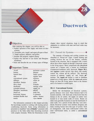
  • 1. Ductwork After studying this chapter, you will be able to: • Explain operation of the supply and return air duct systems. LJ Assemble, join, install, and repair all types of duct. ^1 Tnstail registers, diffusers, and grilles. ^| Insulate and properly support piping. • Explain why and how to use mastic and fiberglass membrane. • Name and describe the use of many types of fittings. Important Terms A-coil bonnet branch lines cfm conventional system diffusers downflow furnace drive cleats ductboard extended plenum fiberglass membrane forced air horizontal furnace insulated flexible duct mastic perimeter system plenum radial system register boot registers return air scrim S-hooks starting collar supply air takeoff trunk line U-channels upflow furnace vapor barrier The information contained in this chapter provides the knowledge needed to working with heating and air conditioning ductwork. Some sizing information is presented as simplified "rules of thumb," consistent with practices in the field, rather than becoming involved with complex formulas. While the illustrations in this chapter show typical situations, keep in mind that adaptation to conform with state and local codes may be necessary. 28.1 Forced Air Systems The majority of heating and cooling systems are classified as "forced air" types. Central heating and cooling involves the use of one furnace, centrally located in the structure, that is equipped with a motor driven fan to blow treated air through a ductwork system to the living spaces. Basic components of a forced air system arc a furnace unit, a remote air conditioner (compressor/condenser unit), ductwork, Figure 28-1, and registers (outlet devices that direct and usually control the volume of the airflow). The ductwork consists of separate "supply air" and "return air" sections. The supply air section is used to distribute treated air to living spaces, while the return air section brings air from the living spaces back to the furnace unit to be heated or cooled again. 28.1.1 Conventional System Before the development of forced-air systems, gravity furnaces were used. These furnaces had to be located centrally, with short runs of ductwork from the furnace to the air outlets. All supply air outlets were located in or near inside walls of rooms. Return air inlets were generally located in or near the baseboards of outer walls. For a period of time after they were intro- duced, forced-air systems were similarly designed, and many existing houses have this type of system. Such an arrangement, with inner wall-located outlets and outer wall-located inlets, is called a conventional system.
  • 2. Heating and Cooling Essentials sufficient and uniform air circulation for maximum comfort. Figure 28-1. Installing an air duct system may be a part of your job in either new construction or remodeling work. 28.1.2 Perimeter System The perimeter system uses forced air and locates the supply air outlets in the baseboard along outside walls, or in floors or ceilings near outer walls Figure 28-2. The supply air "blankets" the wall against drafts (heating mode), or radiant heat during the cooling mode. This air circulates inward to a return air grille located in an inside wall where it is drawn off and returned to the furnace for retreatment. The perimeter system provides 28.2 Furnace Classifications All forced air furnaces are classified according to the direction of the airflow for Ihe supply air. The upflow and downflow furnaces are most common, but horizontal- flow models are necessary for some applications. 28.2.1 Upflow Furnace The upflow furnace is normally located in a base- ment or closet, Figure 28-3. The supply air duct system is attached to the furnace plenum (sometimes called the bonnet), a sheet metal chamber anchored to the top of the furnace with sheet metal screws. The air conditioning evaporator coil is mounted on top of the furnace, but inside the plenum. The supply air duct is often insulated to help maintain the temperature of the treated air. Return air enters the bottom of the furnace. The blower serves for both heating and air conditioning mode, but airflow direction remains the same. 28.2.2 Downflow Furnace A downflow furnace is usually used in a building having a crawl space under the first floor, or in a mobile • ; • - : • • Figure 28-2. The perimeter system uses outlets located along outside walls.
  • 3. Chapter 28 Ductwork Flue or vent Air filter or electronic air cleaner Figure 28-3. An upflow furnace has a top-mounted plenum to distribute supply air. Upflow units are typically located in a basement. home, Figure 28-4. The air conditioning evaporator coil is mounted on the bottom of the furnace, inside the plenum. Supply air travels from the plenum through ductwork to the living spaces. Return air enters the top of the furnace. The blower serves for both heating and air conditioning. 28.2.3 Horizontal Furnace This horizontal furnace is designed for use in a crawl space or attic, Figure 28-5. Supply air exits at one end and return air enters through the other end. This means the ductwork is located in the crawl space or in the attic, along with the furnace. These horizontal furnaces are usually electric, but gas, oil, or heat pump can be used. Air Conditioning Evaporators The A-coil is the most popular type of air condi- tioning evaporator for residential systems. The slant- coil and upright-coil types are primarily used for commercial and industrial systems. Commercial and many industrial air conditioning systems operate the same as residential types. The components are simply bigger (and easier to repair). See Figure 28-6. 28.3 Distribution Systems There are two types of duct systems commonly used for supply air distribution. They are the radial system, which uses strictly round pipe, and the extended plenum system, which combines round pipes with rectangular ducts. 28.3.1 Radial Piping System A radial system is one that uses round pipe running directly from the plenum to the register hoot (component that is used to connect the pipe to the outlet registers). There is a separate run from the furnace plenum to each register boot. These piping runs radiate from the furnace plenum, Figure 28-7. This system is practical where the piping runs are located in an attic or crawl space. The radial system is most economical and easiest to install, but is not prac- tical if the furnace cannot be centrally located. Any
  • 4. Heating and Cooling Essentials Extended plenum Figure 28-4. In a mobile home, or a building with a crawl space instead of a basement the downflow furnace is commonly installed. The plenum is below the unit. 'Air filter Flue Figure 28-5. A horizontal furnace is usually located in an attic or a crawl space.
  • 5. Chapter 28 Ductwork A-coil Supply air ^ Supply air Liquid line Suction Slant coil Supply air Liquid tine Condensate catch pan Equalizer Condensate drain Return air Suction Return air Upright coil Liquid line Suction Supply air Condensate catch pan Condensate drain Condensate catch pan Condensate drain Figure 28-6. The three types of air conditioning evaporators. In residential installations, the A-coii type is most commonly used. building that is odd-shaped or long cannot use the plenum is extended with rectangular duct, and all radial system. 28.3.2 Extended Plenum System An extended plenum system, Figure 28-8, combines rectangular duct with round pipes. The furnace round pipes branch out at right angles from the extended plenum. This permits short lengths of round pipe to reach the registers. For a neat appearance, the round pipes are normally installed in the spaces between the flooring joists. It is necessary to cut a hole and add a register boot at the end of each run. Stack pipe Register boot Round pipe Takeoff or start collar Figure 28-7. The radial piping system uses round pipes running straight to the register boots. In this exampie, the stack pipe nil- +/-t on nnnar flr^nr fnr fi'mtrihl itiDn .-..-.-., *^
  • 6. Heating and Cooling Essentials Branch piping Register boot Plenum Furnace Side takeoff Extended plenum Figure 28-8. Round branch piping extends outward from an extended pienum formed with rectangular duct. 28.4 Distribution System Components-^ The "supply air" distribution system includes the plenum, the main trunk line, and all the branches serving different living spaces. Each branch terminates in a register that directs and usually controls the volume of the airflow. Another system of air duct serves to return air from the living spaces for heating or cooling. This system is called "return air," and includes another main trunk line and all its branches. 28.4.1 Plenum (Bonnet) The first fitting to be installed on any system is the plenum, sometimes called a bonnet. Figure 28-9. It is usually made of 30-gauge, galvanized sheet metal, forming a chamber that is attached to the furnace outlet, Figure 28-9A. The plenum functions as an air- mixing chamber before sending the air to the living spaces. It also provides the necessary surface for attaching takeoffs and starting collars. The cooling Plenum parts Plenum kit with evaporator A B C Figure 28-9. A plenum can be fabricated in the field (A, B) or it may be assembled from a factory kit (C).
  • 7. Chapter 28 Ductwork evaporator is located inside the plenum, Figure 28-9B, and the supply air duct attaches to the plenum. The furnace manufacturer offers a plenum kit along with the necessary evaporator. For adding air conditioning to a previously installed furnace, some sheet metal work may be required. After all parts are assembled and screwed together, the seams must be anchored with .sheet metal screws and sealed with mastic (a nontoxic adhesive material used for permanently sealing joints and seams). See Figure 28-9C. Ductboard made from compressed fiberglass is becoming increasingly popular for plenums and rectangular duct. Ductboard is inexpensive, easy to work with, cuts with a knife, and is already insulated. Applying insulation by hand to metal ducts is often necessary, but is time-consuming and costly. See Figure 28-10. Ductboard Insulation Mastic 28.4.2 Round Metal Pipe Round pipe can be used as a main trunk line or a branch line, in both supply air and return air situations. Round metal pipe has the most efficient charac tens tics, and is commonly used. For heating only, the round pipe supplying air to a register outlet need only be 6" in diameter. For air conditioning, or combined heating and cooling, the pipe should be 8"in diameter. Additional 6"- runs are often used to obtain required capacity. Standard round pipe comes in 30-gauge, 3"-14" in diameter, and in 2', 3', 5', and 10' lengths. All round pipe is factory crimped on one end for easy insertion into another length of pipe, See Figure 28-11. Seam Figure 28-10. A plenum can be fabricated from ductboard, which is less expensive than installing insulation by hand on a metal plenum. Crimped end Figure 28-11. Hound pipe for branch lines can easily be snapped together at the seam. The crimped area at one end allows the pipe to be slipped inside the next section of pipe, forming a joint 28.4.3 Rectangular Duct Rectangular duct is 30-gaugc, galvanized sheet metal, and mainly used as a trunk line, or "extended plenum." Rectangular duct is widely used in the north- eastern and northwestern parts of the United States. It is used as a spacesaver and can be easily routed in overhead space between floor joists, or in an attic. Branch lines consisting of round pipe come off the extended plenum to transport air to a register. A branch line begins with a starting collar or takeoff installed on the extended plenum, (main trunk line). The end of the extended plenum must be blocked wilh an end cap that is anchored with sheet metal screws and sealed with mastic. See Figure 28-12. 'Takeoff Rectangular duct Plenum End cap Figure 28-12. An extended plenum, formed from rectangular duct, has a takeoff fitting at one end and a cap at the other.
  • 8. Heating and Cooling Essentials 28.4.4 Insulated Flexible Duct As shown in Figure 28-13, insulated flexible duct consists of several layers, each with a specific func- tion. The core is usually two plies of polyester film used to encapsulate the galvanized steel wire helix. The purpose of the wire helix is to help flexible duct keep its shape. The insulation is a fiberglass blanket, varying in thickness, depending on the R-valuc. Many states have adopted energy codes for flexible duct that require certain R-values for code approval. A basic requirement is an R-value of 4.3, but Florida requires an R-6, and Washington and Oregon require R-8. Scrim is a high-tensile-strength, fiberglass mesh that provides more protection protect the insulation and inner core. The vapor barrier is a plastic jacket or sleeve that encloses the product. Major Duct Types CORE shields fiberglass Vapor barrier HELIX steel wire coil SCRIM protects insulation Figure 28-13. This cutaway view shows the construction of a typical insulated flexible duct. Round metal pipe Insulated flexible duct Rectangular duct Pros 1. Excellent airflow characteristics 2. Longer-lasting than flexible duct 1. Pre-insulated 2. Ease of installation 3. Reduced labor costs 4. Eliminates some fittings 1. Spacesaver; can use space between floor studs 2. Longer-lasting than flexible duct Cons 1. If required, insulation must be installed 1. Not as long-lasting as metal duct 2. Some reduction in airflow 3. Must be fully extended (cannot make sharp bends) 1. If required, insulation must be installed Figure 28-14. Advantages and disadvantages of three types of air duct. 28.5.1 Sizing the Extended Plenum The extended plenum is sized according to the number and sizes of round pipe it serves. It is easier to have an extended plenum the same width throughout, therefore, all the pipes are counted and the entire extended plenum is sized accordingly. Rectangular duct Comparison of ductwork types Various types of ductwork are available for use in a heating and air conditioning system. Because they were all designed for a particular application, they have different strengths and weaknesses. Figure 28-14 is a list of some pros and cons of the major duct types. 28.5 System Efficiency # An efficient residential heating/cooling system will move air at the proper velocity and quantity to each room, and enter that room at the proper location. Velocity is important: air that is moving too fast creates uncomfortable drafts and makes more noise as it comes through the system. Air moving too slowly will not have enough speed to be thrown across the room or up the wall. Sec Figure 28-15. Rules of Thumb Air should travel from the furnace/air conditioner throughout the system at an average velocity of about 700 ft./min. On average, most system resistance to airflow is approximately 0.08 (0.075) static pressure (0.10 Supply air, 0.05 return air). With an air velocity of about 700 ft/min,, air conditioners are designed to move 400 CFM PER TON, and furnaces at 12 CFM/1000Btu. In general, 1 CFM of air is required to heat or cool 1 or 1-1/4 sq. ft. of floor area. Figure 28-15. Regular use of these rules of thumb will help you solve forced-air system problems.
  • 9. Chapter 28 Ductwork used for extended plenums is 30-gauge, galvanized sheet metal, 8" deep, 60" long, and comes in standard widths of 10", 14", 18", 24" and 28". One of these standard sizes should provide the needed capacity, but any length of duct can be cut to a shorter length. 28.5.2 Rule of Thumb for Determining Plenum Size To determine the width required for an extended plenum, counl the number of round pipes it will serve, Figure 28-16. For 6" round pipes, multiply this number by 2, then add 2 — the total is the required duct width in inches. For 8* round pipes, multiply by 3, then add 2. If the desired size is not available, choose the next larger size. See EXAMPLES: A duct serving four 6" round pipes will have a widthof4x2 = 8 + 2 = 10. A duct serving five 8" round pipes should have a width of 5 X 3 = 15 + 2 = 17. Since rectangular duct is not available in a 17" width, use the next larger standard size, which is 18". 28.5.3 Rule of Thumb for Determining Size of Branch Lines 1. Determine square footage of the room. Length of room, times width of room, equals square footage. 10'X 12'= 120 sq.ft. 2. Determine cfm of air needed to supply the room, cfm means "Cubic Feet per Minute" and defines the amount of air flowing. One cfm of air is required to heat or cool 1.00-1.25 sq. ft. of floor area. EXAMPLE: A 120 sq. ft. room will require between 96 and 120 cfm. 6" pipes Figure 28-16. The number and size of round pipe branch lines determines the width of the extended plenum. 3. Select pipe(s) size according to cfm needed. How much air can a given diameter of pipe carry? A 120 sq. ft. room requiring 96-120 cfm will need one 6" pipe (110 cfm), or use a combination to total about 96-120 cfm. 120 -f 1.00= 120 120- 1.25 = 96 Square footage Room size cfm required 64 (8X8) 51-64 80 (8X10) 64-80 100 (10 X 10) 80-100 120 (10 X 12) 96-120 150 (10 X 15) 120-150 200 (12.5 X 16} 160-200 256 (16X 16) 205-256
  • 10. Heating and Cooling Essentials Pipe size (diameter 4" 5" 6" 7" 8" 10" 12" 14" Avg. cfm @ Static pressure 30 cfm 65 cfm 110 cfm 160 cfm 230 cfm 410 cfm 680 cfm 1000 cfm Straight cut Right cut Left cut 28.5.4 Provide Adequate Airflow A furnace located in a small utility room or closet may not receive a sufficient amount of air for proper combustion. If the furnace room is closed off, provide an adequate air supply by installing two grilles in a door or wall facing a well-ventilated area, Figure 28-17. One grille should be in a high-wall position or at top of the door, and the other should be in a low position. 28.6 Ductwork Tools Persons working with air duct commonly use the special hand tools shown in Figure 28-18. The name of the tool describes its use. Other basic hand tools are also needed. These might include a trouble light, Return air grilles Plenum Note: Aviation snips are used for cutting holes in sheet metal. Never use them to cut wire. 1"X 30" tape Ball pein hammer Figure 28-17. Two grilles in a closet door provide sufficient airflow for furnace operation and return air. Hand crimper Figure 28-18. Hand tools often are named according to the job they perform.
  • 11. Chapter 28 Ductwork battery operated drill, chisel, gloves, lineman's pliers, diagonal cutters, and longnose pliers. NOTE: Aviation snips are used for cutting openings in sheet metal. Never use them to cut wire. 28.7 How to Lay out a Duct System —# The heating and cooling units should be matched to the square footage of the building's floor space. In addi- tion, they should be able to distribute a set quantity of air (measured in cubic feet per minute, or cfm) to the living area through the duct system, Figure 28-19. A living space of 1200 sq. ft. is matched up with a 100,000 Btu furnace and a 3-ton air conditioner, Figure 28-19A. Come off the plenum with one or two main trunk lines having a total capacity of 1200 cfm, running toward the living areas. Figure 28-19B. EXAMPLES: Two 12" round duct main trunks @ 620 cfm each = 1200 cfm Three 10" round duct main trunks @ 400 cfm each = 1200 cfm With the main trunk lines installed, begin branching from the mains with smaller lines running to the various rooms. Always keep a constant rate of airflow (cfm) to the various rooms. A branch line must properly reduce in size to maintain a constant airflow from the trunk line. A vclocimeter or anemometer. Figure 28-20, is often used to check and correct airflow problems. Such meters can read velocity (speed), cfm (flow), and temperature. 28.8 Installing Startinj and Takeoffs - Collars Starting collars and takeoffs are installed on the plenum to begin a "run." A starting collar is used with round duct, while a takeoffis used with rectangular duct. 28.8.1 Starting Collars for Round Duct It is best to mount the starting collar on the side of the plenum, 6" below the top, to ensure proper mixing of the air. Never install a collar on top of the plenum. To install a starting collar, first mark the proper size opening with a pencil or metal scribe, Figure 28-21. Next, pierce the metal surface with a sharp tool and use snips to cut the opening. Then, insert the collar into the opening and fold the tabs down inside the plenum. Finally, secure the collar with three sheet metal screws and seal it with mastic. Sq. Ft. of Floor Area 400 800 1,200 1,600 2,000 Furnace BTU's 33,000 67,000 100,000 133,000 167,000 Air Conditioner Tonnage 1 Ton 2 Ton 3 Ton 4 Ton 5 Ton CFM of Air Movement 400 800 1,200 1,600 2,000 Dimensions 4" Round 5" Round 6" Round 21 /4"X 10" 21 /4"X12" 31 /4" X 10" 3V4"X 12" 7" Round 31 /4"X14" 8" Round 8" X 8" 9" Round 10" Round 12" X 8" 12" Round 16"X8" 14" Round 16" Round Approx. CFM 30 60 100 60 70 100 120 150 140 200 260 290 400 440 620 660 930 1300 Sq. In. 12.57" 19.64" 28.27" 23.00" 27.00" 33.00" 39.00" 38.48" 46.00" 50.27" 64.00" 63.62" 78.54" 96.00" 113.09" 128.00" 153.93" 201.06" B Figure 28-19. A—Heating and cooling units floor area. B—Approximate cfm of airflow (at 700 ft./min.) for different-size ducts. matched to a velocity of 28.8.2 Takeoff for Rectangular Duct Manufactured takeoffs arc available in many sizes, such as 8"x 8", I2"x 8", 14"x 8", or 16"x 8", and mount easily on any side of the plenum. It is best to mount the takeoff 6" below the top of the plenum to ensure proper mixing of the air, Figure 28-22. When the furnace is located at one end of the house, the extended plenum may run to the opposite end. When the furnace is located at the center of the house, two takeoffs are used to provide an extended plenum on each side of the furnace.
  • 12. Heating and Cooling Essentials Takeoff Figure 28-20. Anemometer is used to obtain airspeed, cfm, and temperature. (Courtesy of Sperry Instruments, Inc.) A B Figure 28-21. A—Mark and cut the opening for the starting collar on plenum. B—Insert the collar and bend tabs over. Secure the collar with three metal screws and seal with mastic. Figure 28-22. Top of the takeoff should be located 6" below the top of the plenum. To install the takeoff, first mark off the proper size opening. Next, pieree the metal surface using a drill or sharp tool and cut the opening with snips. Then, insert the takeoff into the opening, and fold the tabs down inside. Finally, secure the takeoff with three sheet metal screws and seal it with mastic. 28.9 Working with Round Metal Pipe-* Standard round pipe is made of 30-gauge, galva- nized metal. Figure 28-23. Round pipe is usually shipped nested, with the seams open, Figure 28-23A. Fittings are usually shipped preformed and ready to install. Each pipe length has an easily connected snap- lock seam. Round the pipe with your hands until the two seam edges meet. Insert the tongue on one seam edge into the groove on the other seam edge. Start at one end of the pipe and work down the seam toward the other end until the entire scam is snapped shut, Figure 28-23B. B End View of Locked Seam Figure 28-23. Round metal pipe. A—Nested pipe lengths with open seams. B—Self-locking seam snaps together when compressed or squeezed with normal hand pressure.
  • 13. Chapter 28 Ductwork 28.9.1 Joining Pipe Lengths Each pipe length has a plain end and a crimped end. Lengths are joined by sliding the plain end of one length over the crimped end of another length. Line up seams for best appearance and push lengths together for a tight joint. Fittings are made similarly. The crimped ends always point in the direction of airflow. Secure each joint with three drive screws evenly spaced around the joint and seal with mastic. See Figure 28-24. Airflow Bead Crimped end Plain end / Magnetic screw holder Drive screw cuts own hole Figure 28-24. Joining pipe lengths. Making connections with round pipe should be step-by-step. A—Each length has a crimped end and a plain end. B—The crimped end slides into the plain end of the next pipe until seated against the bead. C—Three drive screws should be used to secure each joint. Temporary wire supports are often used to hold pipe steady while connections are being made. 28.9.2 Cutting Round Pipe The last length of duct in a run usually must be cut, Figure 28-25. Do not snap the seam together until after the cut is made. Hold the last piece of unformed pipe in place and mark where it is to be cut. Your cutting mark should be on the plain (not crimped) end. Be sure to allow enough extra length for the cut end to slip over the crimped end of the preceding piece, up to the bead. Draw a straight cutting line across the pipe, then make the cut with tin snips. When you make the cut, the tin snips will squeeze the snap-lock seam edge closed. Before you can form the pipe, you will have to pry the seam open again, using a screwdriver. If you need to cut a piece of pipe that is already formed, use a hacksaw. Make a continuous line around the pipe to follow while cutting. Support the round pipe between two wood blocks or other flat pieces, then saw with smooth, even strokes, beginning at the seam. Because of the hacksaw frame, you will only be able to saw part way through the pipe. You will need to rotate pipe and start again with saw on top. Continue in this manner until the cut is complete. 28.9.3 Adjustable Elbows Adjustable elbows can be conformed to the desired angle. A 90°adjustable elbow can be twisted to form any angle from 0°-90°, Figure 28-26. A 45° adjustable elbow is also available. Insert the crimped end to move with the direction of airflow. Install the elbow and secure the joint with sheet metal screws, then seal it with fiberglass tape and mastic. Do not use ordinary duct tape. 28.9.4 Sealing Collars Fiberglass reinforcing membrane will wrinkle when it is wrapped around a joint between round and rectangular ducts. To make the membrane material lie Cutting line Last piece of pipe A B Figure 28-25. In a branch run, the last piece must usually be cut to size. A—Mark the cut with a pencil or scratch awl on the
  • 14. Heating and Cooling Essentials Adjustable Elbow 90° 45° Figure 28-26. Adjustable elbows are convenient for making all types of turns. They are available in all round duct sizes. flat, use a utility knife, to make a series of slices about every two inches along its edge. When the material is wrapped around the round duct, the tabs will fan out and lie flat against the rectangular duct, Figure 28-27. 28.10 Extended Plenum System # Begin with the takeoff fitting in the plenum, and work outward. When a branch pipe comes off the top Figure 28-27. After securing the collar with sheet metal screws, seal the collar with membrane and mastic. This prevents leaks due to vibration. Cutting slits in the membrane will help it lie flat. of the extended plenum, install the starting collar before assembling the rectangulai" duct. Side staiting collars or takeoffs can be installed in the extended plenum after the run is completed. See Figure 28-28. Support the duct at intervals with hangers or straps. Be .sure to keep ducts at least one inch from joists and other combustible materials. Close the end with an end cap. After completing the extended plenum with starting collars or takeoff fittings attached, install branch runs to connect with outlets, insulate all supply ducts and pipes that are located in unheated areas. 28.10.1 Working with Rectangular Duct Most rectangular duct is made of 28-gauge galva- nized sheet metal in 4' lengths. Each duct length is made up of two half sections, as shown in Figure 28-29. Branch piping Plenum Figure 28-28. An extended plenum system uses side takeoff fittings to connect branch lines. A centrally located furnace may have two extended plenums, one on each side.
  • 15. Chapter 28 Ductwork A B C Figure 28-29. How to assemble rectangular duct. A—Match the ends of the two half sections. B—Start the edge channels. C—Slide the two sections together. To form a length, place the two half sections on the floor with the "S-hook" ends up. Pick up one piece and engage its edge channels with the channels on the other piece, then slide the two together. After assembling a section of duct, hammer each channel snug for a tight fit. This can be done as shown in Figure 28-30. Hang the assembled duct over a sturdy board suspended between two sawhorses so the seam lies flat on the board edge. Use a ball pcin hammer to tighten the seam. Rectangular duct is joined with "S-hooks" and drive cleats, Figure 28-31. One end of each section has formed S-hooks on the long edges and "U" channels for the drive cleats on the short edges. The other end has plain long edges, with U-channels on the short edges. Join pieces by inserting a plain end into the S-hooks of the next piece, as shown in Figure 28-31B. Slide drive cleats through the U-channcls to lock the pieces together, Figure 28-31C. Drive cleats are 10" long and used on 8" rectangular duct. When the drive cleats arc in place, bend ends down over duct to complete and secure the joint. Seal the joint with mastic. Where a shorter length is required, cut the two pieces before forming the duct. Always cut the plain end, not the end with the S-hook connection. Measure carefully, then cut both pieces to the same length with tin snips, Figure 28-32. After cutting, use a sturdy screwdriver to pry the edge channels to their original form. Cut back the corners of the new end and use a hand scamcr to form a new U-channel on the short edge of each piece. Figure 28-30. Use a ball pein hammer on each seam for a tight fit. S-hook B U-channel Figure 28-31. Joining rectangular duct, using S-hooks and drive cleats. Figure 28-32. Measure carefully, then use snips to cut duct pieces to size. 28.10.2 Cutting Openings To begin branch pipe runs, openings must be cut in the plenum. Figure 28-33. These openings may be rectangular or round, depending upon whether a
  • 16. Heating and Cooling Essentials Figure 28-33. Installing a top-mounted takeoff. A—Draw the outline for the opening. B—Punch a hole to use when starting the cutting snips. C—Cut around the outline. starting collar or takeoff is used. Make a template of the opening required and draw its outline accurately on the metal to be cut, Figure 28-33A. Punch a hole through the sheet metal within limits of the opening, using a hammer and chisel or similar tool, Figure 28-33B. Insert aviator snips and cut to the outline, then around the outline until the opening is complete, Figure 28-33C. When a branch pipe will be run from the top of an extended plenum, the opening must be cut and the takeoff or starting collar installed before the plenum is fastened in place. Openings on the sides of the plenum can be made at any time. 28.10.3 Rectangular 90° Elbows Rectangular elbows are not adjustable, but are available in 90° "long-way" or 90° "short-way" forms, Figure 28-34. They are also available in 45° configu- rations. A long-way elbow changes the direction of the Long-way Short-way long dimension, and the short-way elbow changes the direction of the short dimension. To form any smaller angle needed, 45° and 90° rectangular elbows can be cut. 28.11 Duct Support All duct should be run in a straight line and supported at regular intervals — typically, 2'-5' — to prevent any sags. The best support material is woven polypropylene strap that comes in various widths. It is sometimes called "webbing strap" and is wide enough so it won't bite into flex duct. Perforated metal strap is a second choice, with steel wire being least desirable. Steel wire is still often used to support round pipe for branch runs. The wire should be wrapped once around the pipe before anchoring to a joist. See Figure 28-35. Window Perforated pipe strap Steel wire Figure 28-34. Rectangular elbows are made in two vari- eties: long-way and short-way. They are not adjustable. Figure 28-35. Three methods of duct support include woven polypropylene strapping, perforated pipestrap, and wire.
  • 17. Chapter 28 Ductwork Keep pipes at least one inch from joists and other combustible material. To prevent heat loss, metal duct is often wrapped with insulation, Figure 28-36. If insu- lating material is appl ied after the duct is already in place, the insulation will have to be slit or stripped to get around the supporting strap or wire. This opening must be rescalcd to maintain insulating effectiveness. Insulation Pipe Roof joist Strapping Insulation Strapping Figure 28-36. Duct is often located in the basement and hidden between floor joists. When located in the attic, it is hung with strapping attached to roof joists. Insulation is often wrapped around the duct to prevent heat loss. 28.12 Working with Insulated Flexible Duct - Insulated flexible duct can be used for main trunk line runs; it also can be used as branching duct, Figure 28-37. This type of duct is available in a variety of sizes, insulation thickness, and specifications, Figure 28-38. Check local building codes for the exact R-value required in your area. To prevent reduced airflow, insulated flexible duct must be fully extended when installed. Avoid any abrupt turns. When a sharp turn is necessary, cut the flex duct at the turn and install a 90-degree elbow of the same diameter. Do not use wire to support flexible duct. Instead, use a wide fabric strapping material and anchor it to wood framing with staples. 28.12.1 Making Connections Making connections with insulated flexible pipe is not difficult, but must be performed properly to obtain Figure 28-37. Insulated flexible duct used for a branch line in a commercial application. The diffuser is sized to drop into the suspended ceiling grid. Figure 28-38. Different sizes and insulation thicknesses are available in insulated flexible duct. correct airflow and prevent leaks. Figure 28-39 shows the connection procedure step-by-step. 28.13 Wall Stack Wall stacks, Figure 28-40, transport air vertically, from floor to floor. In residential applications, stacks carry air to high-wall or second-floor registers from a basement or crawl space. They can also be used to carry air to baseboard or low-wall registers from attic piping. 28.13.1 Installing Wall Stack If possible, work from the basement. As each section is attached, push the stack up into the stud space and attach the next section, Figure 28-41. Continue until the top of the stack reaches the register box or lilting to which it will connect. Reduce the
  • 18. Heating and Cooling Essentials 4" metal sleeve D Figure 28-39. Connecting lengths of insulated flexible duct. A—Cut completely around and through duct with knife or scissors. Cut wire helix with heavy-duty snips or side cutters. B—Peel back the jacket and insulation from core. Butt two cores together on a standard 4" metal sleeve . C—Tape core together with at least two wraps of duct tape. Secure with two approved clamps. D—Pull jacket and insulation back over cores. Tape jackets together with two wraps of tape, then mastic sealant. 28.14 Registers and Diffusers Figure 28-40. Rectangular duct is used to provide vertical passages (wall stacks) that carry treated air from floor-to- floor of a building. This stack is being fabricated for use in an office building. Note: The worker should be wearing safety glasses. length of last section as required. When stack must be lowered from above, enlarge openings as necessary and lower stack into the stud space as it is assembled section by section. To join two sections of stack (or "riser") duct together, "S" cleats can be used to secure the long sides of the duct. Sheet metal screws should be applied on the shorter sides of the ducting, and if needed, can be used on the longer dimension. The seams are then sealed with mastic. The same care should be taken when connecting with the stack heads or boots, Figure 28-42. The final fitting in the duct system used to move air to its destination is the register box, or "boot." Due to the numerous locations and difficult areas registers must fit, boots are available in a variety of shapes and sizes, Figure 28-43. Supply air is released into a room Wall studs Drywall Floor joists Floor Figure 28-41. In residential installations, wall stack is gener- ally pushed up into the wall from the basement. When cutting openings for a stack, use a flashlight and mirror to check for obstructions between studs.
  • 19. Chapter 28 Ductwork 31 /4" 21 /4" Wall stack Boot Boot 8" pipe 6" pipe Figure 28-42. Wall stack duct is designed to fit between the studs inside a wall. Different sizes include 2-1/4" or 3-1/4" deep by 10", 12" or 14" wide. Standard length of a stack section is 24". through registers or diffusers. Both have dampers or vanes for controlling the amount of air, but diffusers also have adjustable vanes for controlling the direction of discharged air. For most effective air movement, registers and diffusers are located in the baseboard on an outside wall, or in the floor near the baseboard. 28.14.1 Locating a Floor Diffuser Locate the diffuser near an outside wall, but at sufficient distance from the wall to clear draperies or other obstructions. Draw an outline of the opening required, then drill a hole in the center of the planned opening. Measure from the hole to the sides of the opening, then go into the basement or crawl space and find the hole position from below. Measure the same distance from the hole to be sure it will clear floor joists or other obstructions. If not, the opening must be shifted. See Figure 28-44. 28.14.2 Installing a Floor Diffuser A typical one-piece diffuser fits into a 12" x 4" rectangular opening in a register boot. Alter locating the proper position, cut a hole in the floor just large enough for the boot to lit snugly. The metal edges of the boot should be level with the floor. Secure the boot in position by nailing it to the floorboards. Insert the diffuser into the boot and anchor it with screws at each end. See Figure 28-45. Floor Wall diffuser Floor Figure 28-43. Placement of supply registers or diffusers is important to ensure a pleasant room temperature. A variety of shapes and sizes are available to meet varying requirements.
  • 20. Heating and Cooling Essentials Figure 28-44. Preparing to cut a floor diffuser opening. A—Measure and trace the opening for the diffuser. B—Drill a centered hole through floor. C—Check clearances from below. Figure 28-45. installing a floor diffuser. A—Cut along the outline with a jigsaw, circular, or reciprocating saw. B—Secure the register box (boot) to floor with nails. C—Install the floor diffuser into boot opening and secure it with screws. 28.15 Return Air System - --# In houses where air can easily circulate to one loca- tion, a central return air grille is adequate. In two-story homes or long ranch designs, a more efficient, yet more expensive system routes air through separate piping from individual rooms back to the furnace for retreatment. The system filter or electronic air cleaner is normally installed where the return air duct attaches to the furnace, Figure 28-46. A disposable filter is usually made of fiberglass within a cardboard frame, Figure 28-47. These filters should be replaced at regular intervals to avoid restricted airflow. An arrow printed on the filter frame .shows direction of airflow. 28.15.1 Return Air Grilles Return air grilles are nonadj us table, and are not equipped with dampers. They should permit unre- stricted ffow of return air back to the furnace. Return air grilles are available in various sizes. A return air grill is normally positioned on an inside wall, in a baseboard on an inside wall, or in the floor next to an inside wall, Figure 28-48. Installing Return Air Grilles When installing wall-type grilles, the floor plate inside the partition must be cut for passage of return air to the duct or enclosed joist space below. It is easier if the Return air Supply air Air filter or electronic cleaner Figure 28-46. For proper circulation, return air is just as important as supply air.
  • 21. Chapter 28 Ductwork Figure 28-47. A disposable air filter can be positioned within a centrally located return air grille. Baseboard grille Floor grille Wall grille Figure 28-48. Return air grilles may be located in floor, ceiling, wall, or baseboard. floor plate can be cut from below the floor. Using the stud space as a return-air duct requires sealing off the stud space just above the grille opening with a 2" x 4" wood block as shown in Figure 28-49. Installing floor type or baseboard type grilles is much the same as installing supply air registers in those surfaces, Figure 28-50. Floor type and baseboard grilles require larger holes than diffusers. 28.15.2 Basement Return-Air System With the return-air grilles installed and the return takeoff fittings attached to the return-air plenum, it is only necessary to complete the runs from the grilles to the furnace. This may be done through sheeted joist and slud spaces, direct ducts, or a combination of the two, Figure 28-51. 28.16 Insulation Insulate all supply ducts and pipes installed in an attic, crawl space, or other unhealed areas. Carefully wrap the insulating material around each pipe and secure with proper glue or by applying tape along the seam, Figure 28-52. WARNING: To avoid a fire hazard, the warm-air plenum and branch ducts must be separated from wood joists, floors, and other structural elements by at least I" of clear space or insulation. 28.16.1 Leaks in Air Ducts Over time, fabric-based duct tape grows brittle and the glue dries out. This permits sections of duct to Studs Return air grille 2" X 4" to seal stud space above grille Adjoining Floor plate cut to allow air passage Metal sheeting Base molding Flooring Figure 28-49. With wall-type grille openings, air is returned to the furnace through stud spaces, sheeted joist spaces, or ducts.
  • 22. Heating and Cooling Essentials Floor opening to joist spaces Temporary support wire Floor opening B Figure 28-50. A—If a large baseboard grille is used, double stud and joist spaces should be prepared. B—Floor type grilles are commonly used when the furnace is located in the basement. come loose and leak air. Air leaks from poorly sealed ducts can be one of the biggest energy and money losers in a home. The California Energy Commission has ruled that fabric-based duct tape can no longer be used for sealing ductwork, and other states are consid- ering a similar ban. Tape Insulation Figure 28-52. Use tape or sealant to close insulation on round pipe. Remove temporary support wires and replace them with strapping. Ducts in homes with high energy-efficiency ratings are usually sealed with mastic and fiberglass rein- forcing membrane, Figure 28-53. Mastic is a nontoxic adhesive-material used for permanently sealing joints and seams for all types of air duct materials. Most Figure 28-53. A—Mastic is available in 1, 2, and 5 gallon recyclable plastic pails. B—Fiberglass reinforcing membrane is designed for use with mastic. A roll is 3" x 50' or 3"x 150'. (Courtesy of RCD Corporation) Return air grille Return air Wood or metal air stop Sheeted joist space Duct opening Figure 28-51. Sheeting, or panning, is easier to install than duct and just as efficient.
  • 23. Chapter 28 Ductwork mastic is water-based, nonflammable, fiber-reinforced, fast drying, and waterproof. Easy application, and clean-up with soap and water are attractive features of the material. Mastic can be applied by brush, trowel, caulking gun, or with a gloved hand. It typically dries to touch in 1 or 2 hours, but unusually wet conditions may require 4-5 hours drying time. Insulation can be installed over mastic that is still wet, but care is needed to prevent excessive movement and loss of seal. 28.16.2 Fiberglass Reinforcing Membrane Fiberglass reinforcing membrane is used with mastic for sealing air leaks in insulation, air ducts, plenums, and fittings. This inorganic woven fiberglass membrane, Figure 28-5313, will not rot, is lightweight and conforms to irregular surfaces. A typical roll is 3" wide x 50' long, or 3" wide x 150' Jong, Figure 28-54. This product is designed to be used with mastic as a reinforcement when there is a gap of 1/4" or more. If the membrane has a sticky side, apply it over the clean metal surface before applying the mastic. If the membrane does not have a sticky side, apply a Ihin layer of mastic and place the membrane in this layer. Add another layer of mastic until the membrane is completely covered. 28.17 How to Use Mastic Before applying mastic or fiberglass reinforcing membrane, the duct surface must be clean and dry, Use a cloth to wipe dust from the surface of the duct, Figure 28-54. If an oily film or grease is present, wipe the duct clean with a damp cloth. If necessary, use a grease-cutting cleaner on the cloth, then wipe thor- oughly dry. 28.17.1 Sealing Joints with Less Than 1/4" Gaps Load the brush with mastic, and coat the entire joint with a continuous strip of the adhesive. Use the end of the brush to work mastic into joint. Spread mastic at least 1" on each side of the joint. Figure 28-55. The mastic should be thick enough to hide the metal surface of the duct (about 1/16" thick). 28.17.2 Sealing Joints with Gaps Greater Than 1/4" Tf the gap in the duct connection is wider than 1/4", use fiberglass reinforcing membrane in addition to maslic. Cut enough membrane to cover the joint, and press the membrane over the joint, Figure 28-56. Tf necessary, first brush a thin layer of mastic on the joint to hold the membrane in place. Finally, cover the membrane with mastic in a layer about 1/16" thick, overlapping the membrane on each side. Cloth Bead Figure 28-54. Mastic will not stick to a dirty surface. Wipe dust off the surface, and clean any greasy residue. Bead Mastic Metal duct Figure 28-55. Joints with a gap of less than 1/4" can be sealed with mastic only. Joint Fiberglass membrane tape Figure 28-56. Gaps of more than 1/4" require use of rein- forcing membrane. Summary This chapter introduced the classifications of forced-air furnaces, based on direction of airflow, and described the difference between conventional and perimeter systems. The major air distribution systems,
  • 24. Heating and Cooling Essentials radial and extended plenum, are described in detail. "Rules of thumb" are provided for sizing a duct system for efficient airflow. Detailed information on laying out and fabricating duct systems is provided, and covers the major types of duct materials: rectangular metal duct, round metal duct, and insulated flexible duct. Directions are given for installation of wall stacks, supply air registers/diffusers, and return air grilles. The use of duct insulation and of fiberglass reinforcing membrane and mastic to seal duct air leaks is covered.