2. July 2005 ASHRAE Journal 55
had to be poured below the existing slab, requiring cutting of
the slab at 30 ft (9 m) centers. The raised floor eliminated this
cost. The floor covered a multitude of sins, which helped pay
for itself.
Given the character of the 45 ft (14 m) high vaulted ceilings
of the aircraft hangars, suspended ceilings were not a desired
interior treatment, which meant that any ductwork would be
exposed and mounted high up at the structure.This would have
posed a challenge in several respects.
Heating would not be done very efficiently, and ventilation
air would be difficult to throw into each cubicle.Any enclosed
spaces, such as conference rooms, would require duct drops
that would be tricky to support and aesthetically difficult to
design. Given that zoning flexibility is needed, variable-air-
volume (VAV) reheat is required, which is much more dif-
ficult to design exposed with a clean appearance compared
to constant volume (CV)
single zone ducts.
The cost of making ex-
posed ductwork acceptable
in appearance was avoided
by the use of the raised floor.
A similar problem would
have been present for the
power and communications
cabling, with exposed race-
ways and power poles.
Right across a narrow
street from the hangars is a
development of new homes.
Having large air-cooled units
sitting next to the hangars
would have been unsightly
and noisy. Locating all the
mechanical equipment, such
as water-cooled direct expansion (DX) units, boiler and cooling
tower inside the building, enabled the appearance of the historic
buildings to be preserved, site landscaping to flourish and noise
to be controlled. Locating HVAC units on the lightly loaded,
barrel-vaulted roof was not an option from structural, aesthetic
and maintenance perspectives.
It is often difficult to accurately compare the cost of systems
at a conceptual level, and this is especially true when the alter-
nate being considered is relatively new. Even if historical data
is available, unfamiliarity can bump up the estimator’s num-
bers. In this case, the developer had a budget of about $85/ft2
($915/m2), which included a seismic upgrade of the building,
new curtain wall and windows, new roof and all new base-
building systems with the shell and core. The HVAC budget
was $8.50/ft2 ($91.50/m2) and the cost of the raised floor about
$7/ft2 ($75.35/m2). This worked with the previous factors to
stay on the budget planned earlier, but required some faith in
the raised floor system pricing.
Architectural Improvements
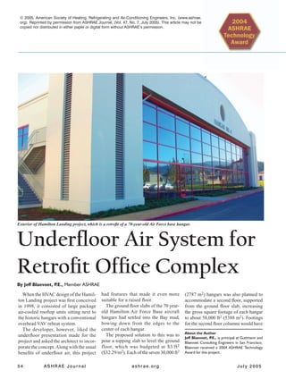
Architecturally, the adaptive reuse was designed to disturb
as little of the existing façade as possible to maintain the
historical integrity of the
hangars. Each hanger has
a large, rectangular floor
plate measuring 240 ft by
120 ft (73 m by 37 m).
Attached to each corner
of the building is a 12 ft
by 12 ft (3.7 m by 3.7 m)
tower that rises 38 ft (11.6
m) above grade. These
concrete towers with 11 ft
by 11 ft (3.4 m by 3.4 m)
clear inside were used for
housing four water-cooled
DX VAV air-conditioning
units on the first floor, and
a boiler and cooling tower
on the second floor.
The building envelope
is comprised concrete walls and a builtup roof with an overall
insulation level of R-19.The glazing is a reflective single-pane
glass with a U-value of 0.95 and a solar heat gain coefficient
(SHGC) of 0.37. The facility has an overall glazing ratio of
approximately 40%, with both the north and south elevations
having over 58% glazing.
Conference room in the interior of an office at Hamilton Landing.
3. 56 ASHRAE Journal ashrae.org July 2005
HVAC System Overview
Four 30-ton (106 kW), water-cooled air-conditioning units,
each sized to provide 15,000 cfm (7079 L/s) of supply air,
serve both floors of each quadrant of the former hangars.These
units receive condenser water from a single 200-ton (703 kW)
forced-draft cooling tower, which provides 80°F (27°C) water,
circulated by a 7.5 hp (5.6 kW) pump. A boiler provides heat-
ing hot water for the perimeter hydronic reheat zones. Hot
water is distributed in a variable-flow pumping scheme with
reverse return and a 2 hp (1.5 kW) hot water pump with vari-
able speed drive.
Access flooring using pedestals 18 in. (0.5 m) above the
ground floor slab and 12 in. (0.3 m) above the second floor slab
were used as supply air plenums. This space also is used for
cable distribution (electric/phone/data) throughout the space.
Individuallyadjustable,floormountedsupplyairdiffusersregu-
late the airflow being supplied to the spaces.These diffusers pro-
vide the occupants with control over the airflow to their space.
The air-conditioning units were designed to maintain indoor
temperatures between 70°F and 78°F (21°C and 25°C) and they
supply air to the underfloor plenums at elevated temperatures of
63°F (17°C). At the perimeter of each floor, linear floor grilles
with hot water linear convectors heat the supply air as required.
The perimeter zones are provided with pressure dependent vol-
ume dampers located in the plenum dividers. This eliminated
the need for fan-powered boxes.
The mechanical system was designed to fit within the exist-
ing corner towers at each hangar. Each air-conditioning unit
occupies the first floor of a single tower, and is a tight fit. The
second floor of the northeast tower contains the boiler while the
second level of the southeast tower houses the cooling tower,
also a tight fit, and its associated pumps.
The first level of each tower has louvers for outdoor-air in-
take and serves as an intake air plenum for the air conditioner.
Second floor louvers provide intake air for the forced-draft
cooling tower, which discharges through the roof, and for
toilet exhaust.
The mechanical equipment is, therefore, entirely integrated
into the original building design, being very unobtrusive. Return
air is transferred through sidewall openings from the towers to
the interior space on each level.
Energy Efficiency
The building design is 29.6% below the 1998 CaliforniaTitle-
24 Energy Standards, and the facility qualified for more than
$55,000 in owner utility incentives.The project site weather cli-
mate has summer conditions (ASHRAE 0.5%) of 87°F (31°C)
DB and 63°F (17°C) WB and winter conditions (ASHRAE
0.2%) of 30°F (–1°C) DB. The typically mild conditions allow
the facility to use many hours of “free cooling” through the use
of an airside economizer.The low wet-bulb temperature ensures
that water cooled equipment can be efficiently applied.
The use of an underfloor system meant that many more econo-
mizer hours were possible with a 63°F to 65°F (17°C to 18°C)
supply air temperature compared to a typical system with 55°F
(13°C) supply air temperature. Utilizing water-cooled equip-
ment allowed the nominal cooling efficiency to be increased
from about 1.1 kW/ton (0.3 kW/kW) for air-cooled equipment,
to 0.7 kW/ton (0.2 kW/kW).
The underfloor air distribution system results in low external
static pressures (0.05 to 0.08 in. w.c. [12.5 to 20 Pa]) reducing
the amount of fan power consumed. Variable frequency drives
(VFDs) were installed on all the supply fans.TheVFDs are used
to maintain a constant static pressure in the supply plenum as
the tenants open and close individual diffusers, or VAV zones
modulate. Motorized dampers were provided behind the existing
building louvers, which are now used for relieving air from the
space when the units are in economizer mode, thus avoiding the
energy use of return or relief fans. The underfloor air system
supplying air at a temperature closer to that of room tempera-
ture results in less concern about operable windows conflicting
with air conditioning. All fans and pumps were specified with
premium efficiency motors.
Conclusion
Many different types of tenant improvements have been
successfully accommodated at Hamilton Landing, including
a YMCA, branch library, full service kitchen and deli, as well
as a multitude of office uses.
This project demonstrates that underfloor air can be a cost-
effective solution for retrofits and speculative office buildings.
The flexibility, comfort, indoor air quality, and energy efficiency
of underfloor air are very affordable, if not lower cost than
conventional overhead systems when executed well.
Underfloor air has been growing in its acceptance in the
United States and many new products, including fan-powered
VAV reheat boxes, and floor diffusers are now available. De-
sign guides, such as the Underfloor Air Distribution (UFAD)
Design Guide published by ASHRAE, have been written, and
more data is available now for cost comparisons, and technical
considerations such as leakage, which will help designers and
decision makers.
Interior photograph of the Hamilton Landing project.