MATHEMATICAL MODEL TO MONITOR STIFF CLAY COMPRESSION INDEX IN WET LAND AREA OF DEGEMA

The stiffness of clay in soil has lots to observe for engineering purpose, these has been monitored through it depositions at various area, the engineering properties of soil were applied to determined the rates of compression in soils, lots of compression index in various types of soil has been carried through experimental applications, empirical model has been applied in several type of soil, these applications predict compression index for numerous formations, but the application of mathematical model thus mathematical methods has not been applied to predict compression index for stiff clay, these application were used through these parameters, it express formations characteristics to developed the system for the study, such application generated the derived equation that produced the model to predict compression index for stiff clay, simulation were applied and it produced theoretical values for stiff clay at various depth, the simulation values were compared with experimental data, both parameters express best fits validating the developed model for the study, compression index were observed to gradually increase with slight variation at different depth, but produced specified compression index within the range for stiff clay.

Recommended
Recommended
More Related Content
What's hot
What's hot (20)
Similar to MATHEMATICAL MODEL TO MONITOR STIFF CLAY COMPRESSION INDEX IN WET LAND AREA OF DEGEMA
Similar to MATHEMATICAL MODEL TO MONITOR STIFF CLAY COMPRESSION INDEX IN WET LAND AREA OF DEGEMA (20)
More from IAEME Publication
More from IAEME Publication (20)
Recently uploaded
Recently uploaded (20)
MATHEMATICAL MODEL TO MONITOR STIFF CLAY COMPRESSION INDEX IN WET LAND AREA OF DEGEMA
- 1. http://www.iaeme.com/IJARET/index.asp 59 editor@iaeme.com International Journal of Advanced Research in Engineering and Technology (IJARET) Volume 6, Issue 12, Dec 2015, pp. 59-72, Article ID: IJARET_06_12_007 Available online at http://www.iaeme.com/IJARET/issues.asp?JType=IJARET&VType=6&IType=12 ISSN Print: 0976-6480 and ISSN Online: 0976-6499 © IAEME Publication ___________________________________________________________________________ MATHEMATICAL MODEL TO MONITOR STIFF CLAY COMPRESSION INDEX IN WET LAND AREA OF DEGEMA Eluozo. S. N Subaka Nigeria Limited Port Harcourt Rivers State of Nigeria Director and Principal Consultant Civil and Environmental Engineering, Research and Development Ode T Department of Civil Engineering, faculty of Engineering Rivers State University of Science and Technology Port Harcourt ABSTRACT The stiffness of clay in soil has lots to observe for engineering purpose, these has been monitored through it depositions at various area, the engineering properties of soil were applied to determined the rates of compression in soils, lots of compression index in various types of soil has been carried through experimental applications, empirical model has been applied in several type of soil, these applications predict compression index for numerous formations, but the application of mathematical model thus mathematical methods has not been applied to predict compression index for stiff clay, these application were used through these parameters, it express formations characteristics to developed the system for the study, such application generated the derived equation that produced the model to predict compression index for stiff clay, simulation were applied and it produced theoretical values for stiff clay at various depth, the simulation values were compared with experimental data, both parameters express best fits validating the developed model for the study, compression index were observed to gradually increase with slight variation at different depth, but produced specified compression index within the range for stiff clay. Key words: Mathematical Model, Stiff Clay and Compression Index
- 2. Eluozo. S. N and Ode T http://www.iaeme.com/IJARET/index.asp 60 editor@iaeme.com Cite this Article: Eluozo. S. N and Ode T, Mathematical Model To Monitor Stiff Clay Compression Index in Wet Land Area of Degema. International Journal of Advanced Research in Engineering and Technology, 6(12), 2015, pp. 59-72. http://www.iaeme.com/IJARET/issues.asp?JType=IJARET&VType=6&IType=12 1. INTRODUCTION It has been thorough examined that saturated stiff clays exhibit a strong pore pressure response that considerably affects the hydraulic and mechanical behaviour of the material Genes et al 2007. Stiff sedimentary clays provide the geological background to many civil engineering projects. In modern years, interest in these types of material has increased, because they are being considered as possible host geological media for underground repositories of high-level radioactive waste (Gens, 2003). They exhibit favourable characteristics, such as low permeability, a degree of self-healing capacity when fractured, significant retardation properties for solute transport, and no foreseeable economic value. Possible shortcomings are the likely need for support of the excavated openings, and sensitivity to chemical actions and to desaturation caused by ventilation. High-level radioactive waste is heat emitting. Therefore the use of stiff sedimentary clays in this type of application brings to the fore the thermal response of this type of material and, especially, the interaction of thermal phenomena with hydraulic and mechanical behaviour. The possible use of these types of clay as geological hosts for radioactive waste has prompted the construction of several underground laboratories. Underground laboratories allow, by the performance of appropriate in situ tests, observation of the clay response in complex situations that mimic some of the conditions likely to be encountered in a deep geological repository. In particular, special attention is paid to the coupled thermo-hydro-mechanical (THM) behaviour of the potential host clay. The observations gathered in the in situ test have provided an opportunity to examine the integrated thermo-hydro mechanical Consolidation is characteristically is classified to be primary consolidation settlement and secondary consolidation settlement. Primary consolidation settlement take place when there is an excess pore water pressure dissipates from the soil layer under the embankment into the surrounding soil. It has been observed that it is gradual dissipation of excess pore water produces corresponding decreases in the soil’s void ratio as the soil consolidates. More so surface settlement consequential from consolidation settlement may range from a few centimeters up to numerous meters; these also depend on the thickness of the clay deposit, in previous loading history it has been observed that the magnitude developed increased stress caused by the new embankment load. Base on these factors predicting the amount of primary consolidation settlement has been noted to be imperative for many civil engineering projects. (Bartlett 2004). The initiations of primary consolidation, the resultant from settlement are ranged between 10 to 15 percent of the amount of embankment placed. For instance, 10-m high embankments are observed to undergo between 1 to 1.5 m of consolidation settlement from compression of the foundation soils. Furthermore, it has been thoroughly observed on large amount of primary consolidation settlement, the period of consolidation settlement is quite long, it is also noted to be between to 2 to 3 years to complete, these are determined on the location and nature of the underlying sediments. Thus, the time-rate of primary consolidation is an imperative design and construction consideration. Looking at primary consolidation, secondary
- 3. Mathematical Model To Monitor Stiff Clay Compression Index in Wet Land Area of Degema http://www.iaeme.com/IJARET/index.asp 61 editor@iaeme.com consolidation it takes long-term form of settlement to occurs under a constant vertical effective stress (i.e., it implies that vertical effective stress may not be changing with time). In secondary consolidation, the excess pore pressure dissipation associated with primary consolidation has in actual fact dissipated, thus secondary consolidation is a decrease in void ratio change that occurs after primary consolidation and progresses under a constant vertical effective stress. Secondary consolidation is characterized by a continuing decrease in void ratio resulting from rearrangement of the soil fabric with time. The magnitude of secondary consolidation usually diminished with time on a settlement versus log of elapsed time plot. Secondary consolidation is also referred to as creep settlement. In general, secondary consolidation settlement is generally much smaller than primary consolidation settlement and ranges from a few centimeters to a few tens of centimeters during the lifetime of bridge structure. (Bartlett, 2004). Various in situ heating tests have been performed involving the observation of the response of natural sedimentary clay. For instance, in the Hades laboratory the following experiments have been performed: (Picard et al., 1994; Bernier & Neerdael, 1996; De Bruyn & Labat, 2002). mineralogy consists mainly of sheet silicates (illite, illite– smectite mixed layers, chlorites, kaolinites), framework silicates (albites, K- feldspar), carbonates (calcite, dolomite, ankerite and siderite), and quartz (Bossart et al., 2002). Opalinus clay behaviour has been intensely studied by means of laboratory and in situ experimental programmes. A synthesis of the main physical and geotechnical parameters is reported in Bock (2001). A significant number of measurements of the in situ stress have been made using different procedures (borehole slotter, undercoring, and hydraulic fracturing). They have been supplemented by geological observations and back-analysis of instrumented excavations. A synthesis of the information available is reported in Wermeille & Bossart (1999) and in Martin & Lanyon (2003). Naturally, the strength and significance of each coupling relationship vary widely (Bai & bousleiman, 1997; Zimmerman, 2000). Observations made during the test did not indicate any desaturation of the clay; it is presumed that the material has remained saturated throughout. Coupled THM formulations for saturated porous media have been proposed by several authors (e.g. Booker & Savvidou, 1985; Katsube, 1988; Kurashige, 1989; Wang & Papamichos, 1999; Kanj & Abousleiman, 2005). 2. GOVERNING EQUATION 02 2 dx dc dx dc V dx cd o (1) Nomenclature = Plastic Index β = Plastic Limit Vo = Void Ratio = Porosity Z = Depth 002 2 dx dc V dx cd (2)
- 4. Eluozo. S. N and Ode T http://www.iaeme.com/IJARET/index.asp 62 editor@iaeme.com Let 0n n n xaC 1 11 n n n xnaC 2 211 1 n n n xannC 01 1 1 0 2 2 n n n n n n xnaVxann (3) Replace n in the 1st term by n+2 and in the 2nd term by n+1, so that we have; 0112 0 1 0 2 n n no n n n xanVxann (4) i.e. 102 112 nn anVann (5) 12 1 10 2 nn anV a n n (6) 2 10 2 n aV a n n (7) for 2 ,0 10 2 aV an (8) (9) Subject equation (16) to the following boundary condition HoCandoC 1 0 x V aaxC 0 10 010 aaoC i.e. 010 aa (10) x V aaxC 0 10
- 5. Mathematical Model To Monitor Stiff Clay Compression Index in Wet Land Area of Degema http://www.iaeme.com/IJARET/index.asp 63 editor@iaeme.com x V a V xC 0 1 01 !2 Ha V oC 1 01 !2 0 1 V H a (11) Substitute (10) into equation (11) 01 aa 0 0 V H a (12) Hence, the particular solution of equation (16) is of the form: x V V H V H xC 0 00 1 0 0 x V V H xC (13) 3. MATERIALS AND METHOD Standard laboratory experiment where performed to monitor compression index of stiff clay at different formation, the soil deposition of the strata were collected in sequences base on the structural deposition at different locations, this samples collected at different location generated variations at different depth producing deposition of stiff clay compression at different strata, the experimental result are applied to compare with the theoretical values to determined the validation of the model. 4. RESULT AND DISCUSSION Results and discussion are presented in tables including graphical representation of compression index of stiff clay Table 1 Predictive Values of stiff clay compression index at Different Depth Depth [M] Predictive of Stiff Clay Cc 0.2 0.00639 0.4 0.012 0.6 0.018 0.8 0.024 1 0.03 1.2 0.036 1.4 0.04
- 6. Eluozo. S. N and Ode T http://www.iaeme.com/IJARET/index.asp 64 editor@iaeme.com Depth [M] Predictive of Stiff Clay Cc 1.6 0.048 1.8 0.054 2 0.06 2.2 0.066 2.4 0.072 2.6 0.078 2.8 0.084 3 0.09 3.2 0.096 3.4 0.102 3.6 0.108 3.8 0.114 4 0.12 4.2 0.126 4.4 0.132 4.6 0.138 4.8 0.144 5 0.15 Table 2 Predicted and Measured of compression index for stiff clay at Different Depth Depth [M] Predictive of Stiff Clay Cc Measured Values of Stiff Clay Cc 0.2 0.00639 5.61E-03 0.4 0.012 0.0116 0.6 0.018 0.0174 0.8 0.024 0.0232 1 0.03 0.029 1.2 0.036 0.0348 1.4 0.04 0.041 1.6 0.048 0.0464 1.8 0.054 0.0523 2 0.06 0.0581 2.2 0.066 0.0639 2.4 0.072 0.0697 2.6 0.078 0.0756 2.8 0.084 0.0814 3 0.09 0.0873 3.2 0.096 0.0931 3.4 0.102 0.0989 3.6 0.108 0.1047 3.8 0.114 0.1106 4 0.12 0.1164 4.2 0.126 0.1223 4.4 0.132 0.1281 4.6 0.138 0.134 4.8 0.144 0.139 5 0.15 0.145 Table 3 Predictive Values of stiff clay compression index at Different Depth Depth [M] Predictive of Stiff Clay Cc 0.2 0.004 0.4 0.008 0.6 0.012 0.8 0.016 1 0.02 1.2 0.024
- 7. Mathematical Model To Monitor Stiff Clay Compression Index in Wet Land Area of Degema http://www.iaeme.com/IJARET/index.asp 65 editor@iaeme.com Depth [M] Predictive of Stiff Clay Cc 1.4 0.028 1.6 0.032 1.8 0.036 2 0.04 2.2 0.044 2.4 0.048 2.6 0.052 2.8 0.056 3 0.06 3.2 0.064 3.4 0.068 3.6 0.072 3.8 0.076 4 0.08 4.2 0.084 4.4 0.088 4.6 0.092 4.8 0.096 5 0.1 5.2 0.104 5.4 0.108 5.6 0.112 5.8 0.116 6 0.12 6.2 0.124 6.4 0.128 6.6 0.132 6.8 0.136 7 0.14 7.2 0.144 7.4 0.148 7.6 0.152 7.8 0.156 8 0.16 Table 4 Predicted and Measured of compression index for stiff clay at Different Depth Depth [M] Predictive of Stiff Clay Cc Measured Values of Stiff Clay Cc 0.2 0.004 0.003 0.4 0.008 0.007 0.6 0.012 0.014 0.8 0.016 0.018 1 0.02 0.022 1.2 0.024 0.028 1.4 0.028 0.029 1.6 0.032 0.034 1.8 0.036 0.038 2 0.04 0.042 2.2 0.044 0.046 2.4 0.048 0.049 2.6 0.052 0.054 2.8 0.056 0.058 3 0.06 0.062 3.2 0.064 0.066 3.4 0.068 0.069 3.6 0.072 0.074 3.8 0.076 0.078
- 8. Eluozo. S. N and Ode T http://www.iaeme.com/IJARET/index.asp 66 editor@iaeme.com Depth [M] Predictive of Stiff Clay Cc Measured Values of Stiff Clay Cc 4 0.08 0.084 4.2 0.084 0.086 4.4 0.088 0.089 4.6 0.092 0.094 4.8 0.096 0.098 5 0.1 0.104 5.2 0.104 0.106 5.4 0.108 0.109 5.6 0.112 0.114 5.8 0.116 0.118 6 0.12 0.122 6.2 0.124 0.126 6.4 0.128 0.129 6.6 0.132 0.134 6.8 0.136 0.138 7 0.14 0.144 7.2 0.144 0.146 7.4 0.148 0.149 7.6 0.152 0.156 7.8 0.156 0.158 8 0.16 0.164 Table 5 Predictive Values of stiff clay compression index at Different Depth Depth [M] Predictive of Stiff Clay Cc 0.2 0.0048 0.4 0.0096 0.6 0.014 0.8 0.0196 1 0.024 1.2 0.028 1.4 0.033 1.6 0.0384 1.8 0.0432 2 0.048 2.2 0.0528 2.4 0.0576 2.6 0.0624 2.8 0.0672 3 0.072 3.2 0.0768 3.4 0.0816 3.6 0.0864 3.8 0.0912 4 0.096 4.2 0.1008 4.4 0.10564 4.6 0.11 4.8 0.1152 5 0.12 5.2 0.1248 5.4 0.129 5.6 0.1344 5.8 0.1392 6 0.144 6.2 0.1488 6.4 0.1536
- 9. Mathematical Model To Monitor Stiff Clay Compression Index in Wet Land Area of Degema http://www.iaeme.com/IJARET/index.asp 67 editor@iaeme.com Depth [M] Predictive of Stiff Clay Cc 6.6 0.158 6.8 0.162 7 0.168 Table 6 Predicted and Measured of compression iTndex for stiff clay at Different Depth Depth [M] Predictive of Stiff Clay Cc Measured Values of Stiff Clay Cc 0.2 0.0048 0.00477 0.4 0.0096 0.00957 0.6 0.014 0.01437 0.8 0.0196 0.01917 1 0.024 0.02397 1.2 0.028 0.02877 1.4 0.033 0.03357 1.6 0.0384 0.03837 1.8 0.0432 0.04317 2 0.048 0.04797 2.2 0.0528 0.05277 2.4 0.0576 0.05757 2.6 0.0624 0.06237 2.8 0.0672 0.06717 3 0.072 0.07197 3.2 0.0768 0.07677 3.4 0.0816 0.08157 3.6 0.0864 0.08637 3.8 0.0912 0.09117 4 0.096 0.09597 4.2 0.1008 0.10077 4.4 0.10564 0.10557 4.6 0.11 0.11037 4.8 0.1152 0.11517 5 0.12 0.11997 5.2 0.1248 0.12477 5.4 0.129 0.12957 5.6 0.1344 0.13437 5.8 0.1392 0.13917 6 0.144 0.14397 6.2 0.1488 0.14877 6.4 0.1536 0.153357 6.6 0.158 0.1584 6.8 0.162 0.16317 7 0.168 0.16797
- 10. Eluozo. S. N and Ode T http://www.iaeme.com/IJARET/index.asp 68 editor@iaeme.com Figure 1 Predictive Values of stiff clay compression index at Different Depth Figure 2 Predicted and Measured of compression index for stiff clay at Different Depth y = 3E-05x2 + 0.0299x + 1E-05 R² = 0.9999 0 0.02 0.04 0.06 0.08 0.1 0.12 0.14 0.16 0 1 2 3 4 5 6 predictivevaluesforstiffclay Depth [M] Predictive of Stiff Clay Cc Poly. (Predictive of Stiff Clay Cc) 0 0.02 0.04 0.06 0.08 0.1 0.12 0.14 0.16 0 1 2 3 4 5 6 PredictiveandMeasuredValuesforStiffClay CompressionIndex Depth [M] Predictive of Stiff Clay Cc Measured Values of Stiff Clay Cc
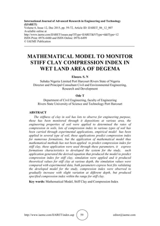
- 11. Mathematical Model To Monitor Stiff Clay Compression Index in Wet Land Area of Degema http://www.iaeme.com/IJARET/index.asp 69 editor@iaeme.com Figure 3 Predictive Values of stiff clay compression index at Different Depth Figure 4 Predicted and Measured of compression index for stiff clay at Different Depth y = -1E-17x2 + 0.02x - 9E-16 R² = 1 0 0.02 0.04 0.06 0.08 0.1 0.12 0.14 0.16 0.18 0 2 4 6 8 10 PredictiveValuesforStiffClay Depth [M] Predictive of Stiff Clay Cc Poly. (Predictive of Stiff Clay Cc) 0 0.02 0.04 0.06 0.08 0.1 0.12 0.14 0.16 0.18 0 2 4 6 8 10 PredictivaValuesforStiffClayonCompression Index Depth [M] Predictive of Stiff Clay Cc Measured Values of Stiff Clay Cc
- 12. Eluozo. S. N and Ode T http://www.iaeme.com/IJARET/index.asp 70 editor@iaeme.com Figure 5 Predictive Values of stiff clay compression index at Different Depth Figure 6 Predicted and Measured of compression index for stiff clay at Different Depth The study has expressed the behaviour of stiff clay in terms its deposition, the stiffness condition are base on the structural behaviour of the soil in terms of engineering properties, these condition may have affected figure one and two were the compression index of stiff clay were observed to gradually increase to the optimum level monitored from it structural setting, slight variation of compression were noted but it is observed to gradually increase to the optimum level, similar conditions were found on the validation parameter i.e. figure two. The compression maintained y = -1E-17x2 + 0.02x - 9E-16 R² = 1 0 0.02 0.04 0.06 0.08 0.1 0.12 0.14 0.16 0.18 0 2 4 6 8 10 PredictiveValuesforStiffClay Depth [M] Predictive of Stiff Clay Cc Poly. (Predictive of Stiff Clay Cc) 0 0.02 0.04 0.06 0.08 0.1 0.12 0.14 0.16 0.18 0 2 4 6 8 PredictiveandMeasuredValuesforStiff ClayonCompressionIndex Depth [M] Predictive of Stiff Clay Cc Measured Values of Stiff Clay Cc
- 13. Mathematical Model To Monitor Stiff Clay Compression Index in Wet Land Area of Degema http://www.iaeme.com/IJARET/index.asp 71 editor@iaeme.com gradual increase to the optimum rate, the results were found to be comparatively fitting with the theoretical values. Figure three and four maintained similar condition like the case of figure one and two, gradual variation of compression were found in figure three and four respectively, variation of parameters that made up the system were found to developed increment on the compression these figures, these were also observed from there fitness. While in figure five and six experiences similar condition, but with slight variation on the increment of compression to the optimum level, the behaviour of stiff clay from it compressibility has been expressed through the developed simulation and experimental values, these were monitored through it fitness between the predictive and the measured values. 5. CONCLUSION The study of stiff clay compression index in wet land area has been developed through empirical methods, but there has been no application of mathematical method in any latest’s literature as observed, empirical solution has been the only concept to monitor the rate of compression of stiff clay, but the application of these modeling techniques were able to predict the compression index of stiff at various depth as universally specified, engineering properties soil or formation characteristics were applied to formulate the system, these expression generated the developed mathematical equation derived to generate model that predict compression index for stiff clay. Such predictive values were compared with other experiment data, both parameters developed best fits validating compression index for stiff clay, the study express various gradual increase of compression index at different depth within the specified rang in for stiff clay in wet land area of Degema. REFERENCES [1] Bartlett,S .F 2004 Estimation of Compression Properties of Clayey Soils Salt Lake Valley, Utah Report Prepared for the Utah Department of Transportation Research Division Civil and Environmental Engineering Department University of Utah [2] A. Gene A Vaunat Garitte B and Wileveau Y In situ behaviour of stiff layered clay subject to thermal loading: Observations and interpretation Ge´otechnique 57, No. 2, 207–228. [3] Gens, A. (2003). The role of geotechnical engineering in nuclear energy utilisation (Special Lecture). Proc. 13th Eur. Conf. Soil Mech. Geotech. Engng, Prague 3, 25–67. [4] Bernier, F. & Neerdael, B. (1996). Overview of in situ thermomechanical experiments in clay: concept, results and interpretation. Engng Geol. 41, Nos 1–4, 51–64. [5] Bock, H. (2001). RA experiment. Rock mechanics analyses and synthesis: Data report on rock mechanics, Technical Report 2000-02. Mont Terri Project [6] Bossart, P., Meier, P. M., Moeri. A., Trick, T. & Mayor, J.-C. (2002). Geological and hydraulic characterisation of the excavation disturbed zone in the Opalinus clay of the Mont Terri rock laboratory. Engng Geol. 66, Nos 1– 2, 19–38. [7] Bai, M. & Abousleiman, Y. (1997). Thermoporoelastic coupling with application to consolidation. Int. J. Numer. Anal. Methods Geomech. 21, No. 2, 121–132.
- 14. Eluozo. S. N and Ode T http://www.iaeme.com/IJARET/index.asp 72 editor@iaeme.com [8] De Bruyn, D. & Labat, S. (2002). The second phase of ATLAS: the continuation of a running THM test in the HADES underground research facility at Mol. Engng Geol. 64, Nos 2–3, 309–316. [9] Picard, J. M., Bazargan, B. & Rousset, G. (1994). Essai thermohydro- me´canique dans une argile profonde: Essai CACTUS, CEC Report EUR 15482 FR. Luxembourg: CEC. [10] Wermeille, S. & Bossart, P. (1999). In situ stresses in the Mont Terri Region: Data compilation, Technical Report 99-02. Mont Terri Project. [11] Martin, C. D. & Lanyon, G. W. (2003) Measurement of in situ stress in weak rocks at Mont Terri Rock Laboratory, Switzerland. Int. J. Rock Mech. Mining Sci. 40, Nos 7–8, 1077–1088 [12] Booker, J. R. & Savvidou, C. (1985). Consolidation around a point heat source. Int. J. Numer. Anal. Methods Geomech. 9, No. 2, 173–184. [13] Katsube, N. (1988). The anisotropic thermo-mechanical constitutive theory for fluid-filled porous materials with solid/fluid outer boundaries. Int. J. Solids Struct. 24, No. 4, 375–380. [14] Dr. Lakshminarayanachari.k, Time – Dependent Two Dimensional Mathematical Model of Air Pollution Due To Area Source with Settling Velocity and Transformation Processes of Primary and Secondary Pollutants. International Journal of Advanced Research in Engineering and Technology, 4(6), 2013, pp. 269 - 277. [15] Kurashige, M. (1989). A thermoelastic theory of fluid-filled porous materials. Int. J. Solids Struct. 25, No. 9, 1039–1052. [16] Kanj, M. & Abousleiman, Y. (2005). Porothermoelastic analyses of anisotropic hollow cylinders with applications. Int. J. Numer. Anal. Methods Geomech. 29, No. 2, 103–126