SlideShare a Scribd company logo
1 of 28
Multi-stage transistor amplifiers
• The following figure shows a two-stage
amplifier connected in cascade.
• The overall gain is the product of voltage gain of
individual stages.
• AV=AV1×AV2
V2/V1×V0/V2=V0/V1
• Where AV = Overall gain, AV1 = Voltage gain of
1st stage, and AV2 = Voltage gain of 2nd stage.
• If there are n numbers of stages, the product of
voltage gains of those n stages will be the overall
gain of that multistage amplifier circuit.
Amplifier Consideration
• For an amplifier circuit, the overall gain of the amplifier
is an important consideration. To achieve maximum
voltage gain, let us find the most suitable transistor
configuration for cascading.
• CC Amplifier
Its voltage gain is less than unity.
It is not suitable for intermediate stages.
• CB Amplifier
Its voltage gain is less than unity.
Hence not suitable for cascading.
CE Amplifier
Its voltage gain is greater than unity.
Voltage gain is further increased by cascading.
The characteristics of CE amplifier are such
that, this configuration is very suitable for
cascading in amplifier circuits. Hence most of
the amplifier circuits use CE configuration.
RC Coupling Amplifier
• The resistance-capacitance coupling is, in short termed as RC coupling.
This is the mostly used coupling technique in amplifiers.
Construction of a Two-stage RC Coupled Amplifier
• The constructional details of a two-stage RC coupled
transistor amplifier circuit are as follows.
• The two stage amplifier circuit has two transistors, connected
in CE configuration and a common power supply VCC is used.
• The potential divider network R1 and R2 and the resistor
Re form the biasing and stabilization network.
• The emitter by-pass capacitor Ce offers a low reactance path
to the signal.
• The resistor RL is used as a load impedance. The
input capacitor Cin present at the initial stage of the
amplifier couples AC signal to the base of the
transistor. The capacitor CC is the coupling capacitor
that connects two stages and prevents DC
interference between the stages and controls the
shift of operating point.
Frequency Response of RC Coupled Amplifier
• Frequency response curve is a graph that indicates the relationship
between voltage gain and function of frequency. The frequency response
of a RC coupled amplifier is as shown in the following graph.
• From the graph, it is understood that the frequency rolls off or decreases for the
frequencies below 50Hz and for the frequencies above 20 KHz. whereas the
voltage gain for the range of frequencies between 50Hz and 20 KHz is constant.
Following equation means that the capacitive reactance is inversely proportional
to the frequency.
Xc=1/2πfc
At Low frequencies (i.e. below 50 Hz)
• The capacitive reactance is inversely proportional to the frequency. At low
frequencies, the reactance is quite high. The reactance of input capacitor
Cin and the coupling capacitor CC are so high that only small part of the
input signal is allowed. The reactance of the emitter by pass capacitor CE is
also very high during low frequencies. Hence it cannot shunt the emitter
resistance effectively. With all these factors, the voltage gain rolls off at
low frequencies.
At High frequencies (i.e. above 20 KHz)
• Again considering the same point, we know that the
capacitive reactance is low at high frequencies. So, a
capacitor behaves as a short circuit, at high frequencies.
As a result of this, the loading effect of the next stage
increases, which reduces the voltage gain. Along with
this, as the capacitance of emitter diode decreases, it
increases the base current of the transistor due to which
the current gain (β) reduces. Hence the voltage gain rolls
off at high frequencies.
At Mid-frequencies (i.e. 50 Hz to 20 KHz)
• The voltage gain of the capacitors is maintained constant in this
range of frequencies, as shown in figure. If the frequency increases,
the reactance of the capacitor CC decreases which tends to increase
the gain. But this lower capacitance reactive increases the loading
effect of the next stage by which there is a reduction in gain.
• Due to these two factors, the gain is maintained constant.
Advantages of RC Coupled Amplifier
• The following are the advantages of RC coupled
amplifier.
• The frequency response of RC amplifier provides
constant gain over a wide frequency range, hence
most suitable for audio applications.
• The circuit is simple and has lower cost because it
employs resistors and capacitors which are
cheap.
• It becomes more compact with the upgrading
technology.
Disadvantages of RC Coupled Amplifier
• The following are the disadvantages of RC coupled amplifier.
• The voltage and power gain are low because of the effective
load resistance.
• They become noisy with age.
• Due to poor impedance matching, power transfer will be low
Applications of RC Coupled Amplifier
• The following are the applications of RC
coupled amplifier.
• They have excellent audio fidelity over a wide
range of frequency.
• Widely used as Voltage amplifiers
• Due to poor impedance matching, RC coupling
is rarely used in the final stages.
Transformer Coupled Amplifier
• We have observed that the main drawback of RC coupled amplifier
is that the effective load resistance gets reduced.
This is because, the input impedance of an amplifier is low, while its
output impedance is high.
• When they are coupled to make a multistage amplifier,
the high output impedance of one stage comes in parallel with the low
input impedance of next stage. Hence, effective load resistance is decreased.
This problem can be overcome by a transformer coupled amplifier.
• In a transformer-coupled amplifier, the stages of amplifier are coupled using a
transformer. Let us go into the constructional and operational details of a
transformer coupled amplifier.
Construction of Transformer Coupled Amplifier
• The amplifier circuit in which, the previous stage is connected to the next
stage using a coupling transformer, is called as Transformer coupled
amplifier.
• The potential divider network R1 and R2 and the resistor Re together form
the biasing and stabilization network.
• The emitter by-pass capacitor Ce offers a low reactance path to the signal.
The resistor RL is used as a load impedance.
• The input capacitor Cin present at the initial stage of the amplifier couples
AC signal to the base of the transistor.
• The capacitor CC is the coupling capacitor that connects two stages and
prevents DC interference between the stages and controls the shift of
operating point.
• This transformer coupling provides good impedance matching between
the stages of amplifier. The transformer coupled amplifier is generally
used for power amplification.
Frequency Response of Transformer Coupled Amplifier
• The figure below shows the frequency response of a transformer coupled
amplifier. The gain of the amplifier is constant only for a small range of
frequencies. The output voltage is equal to the collector current multiplied
by the reactance of primary.
• At low frequencies, the reactance of primary begins to fall, resulting in
decreased gain. At high frequencies, the capacitance between turns of
windings acts as a bypass condenser to reduce the output voltage and
hence gain.
• So, the amplification of audio signals will not be proportionate and some
distortion will also get introduced, which is called as Frequency distortion
Advantages of Transformer Coupled
Amplifier
.
• The following are the advantages of a transformer coupled
amplifier −
• An excellent impedance matching is provided.
• Gain achieved is higher.
• There will be no power loss in collector and base resistors.
• Efficient in operation.
Disadvantages of Transformer Coupled
Amplifier
The following are the disadvantages of a transformer coupled
amplifier −
• Though the gain is high, it varies considerably with frequency.
Hence a poor frequency response.
• Frequency distortion is higher.
• Transformers tend to produce hum noise.
• Transformers are bulky and costly.
Applications
The following are the applications of a
transformer coupled amplifier −
• Mostly used for impedance matching
purposes.
• Used for Power amplification.
• Used in applications where maximum power
transfer is needed.
Direct Coupled Amplifier
• The other type of coupling amplifier is the
direct coupled amplifier, which is especially
used to amplify lower frequencies, such as
amplifying photo-electric current or thermo-
couple current or so.
• Direct Coupled Amplifier
• As no coupling devices are used, the coupling
of the amplifier stages is done directly and
hence called as Direct coupled amplifier.
Construction
• The transistor in the first stage will be an NPN
transistor, while the transistor in the next
stage will be a PNP transistor and so on. This is
because, the variations in one transistor tend
to cancel the variations in the other. The rise
in the collector current and the variation in β
of one transistor gets cancelled by the
decrease in the other.
Operation
• The input signal when applied at the base of
transistor T1, it gets amplified due to the
transistor action and the amplified output
appears at the collector resistor Rc of
transistor T1. This output is applied to the base
of transistor T2 which further amplifies the
signal. In this way, a signal is amplified in a
direct coupled amplifier circuit.
Advantages and Disadvantages
• The advantages of direct coupled amplifier are as
follows.
• The circuit arrangement is simple because of minimum
use of resistors.
• The circuit is of low cost because of the absence of
expensive coupling devices.
• The disadvantages of direct coupled amplifier are as
follows.
• It cannot be used for amplifying high frequencies.
• The operating point is shifted due to temperature
variations.
Applications
• The applications of direct coupled amplifier
are as follows.
• Low frequency amplifications.
• Low current amplifications.
Comparisions
• Let us try to compare the characteristics of
different types of coupling methods discussed
till now.
• Assignment
• ?

More Related Content

Similar to unit 1 ppt 2 Multi-stage transistor amplifiers (1).pptx

Similar to unit 1 ppt 2 Multi-stage transistor amplifiers (1).pptx (20)

A Class-C Power Amplifiers Type of Tuned Amplifiers
A Class-C Power Amplifiers Type of Tuned AmplifiersA Class-C Power Amplifiers Type of Tuned Amplifiers
A Class-C Power Amplifiers Type of Tuned Amplifiers
 
Voltage Amplifier
Voltage AmplifierVoltage Amplifier
Voltage Amplifier
 
Amplifier.pptx
Amplifier.pptxAmplifier.pptx
Amplifier.pptx
 
Presentation 2
Presentation 2Presentation 2
Presentation 2
 
Multistage amplifier
Multistage amplifierMultistage amplifier
Multistage amplifier
 
EC2-NOTES-PPT.ppt
EC2-NOTES-PPT.pptEC2-NOTES-PPT.ppt
EC2-NOTES-PPT.ppt
 
ADE ALL UNITS.pdf
ADE ALL UNITS.pdfADE ALL UNITS.pdf
ADE ALL UNITS.pdf
 
Amplifier classes
Amplifier classesAmplifier classes
Amplifier classes
 
Transistor
TransistorTransistor
Transistor
 
Power amplifiers
Power amplifiersPower amplifiers
Power amplifiers
 
Coupling of Amplifiers- Direct coupled amplifier
Coupling of Amplifiers- Direct coupled amplifierCoupling of Amplifiers- Direct coupled amplifier
Coupling of Amplifiers- Direct coupled amplifier
 
Oscillator
OscillatorOscillator
Oscillator
 
Bjt+and+jfet+frequency+response
Bjt+and+jfet+frequency+responseBjt+and+jfet+frequency+response
Bjt+and+jfet+frequency+response
 
Audio amplifier
Audio amplifier Audio amplifier
Audio amplifier
 
Class a amplifier
Class a amplifierClass a amplifier
Class a amplifier
 
orca_share_media1489816591592333333333.pptx
orca_share_media1489816591592333333333.pptxorca_share_media1489816591592333333333.pptx
orca_share_media1489816591592333333333.pptx
 
Lesson4
Lesson4Lesson4
Lesson4
 
PPT- RVN (1).pptx
PPT- RVN (1).pptxPPT- RVN (1).pptx
PPT- RVN (1).pptx
 
Basic Electronics 4 by Dr. Mathivanan Velumani
Basic Electronics 4 by Dr. Mathivanan VelumaniBasic Electronics 4 by Dr. Mathivanan Velumani
Basic Electronics 4 by Dr. Mathivanan Velumani
 
Transistor Amplifire.pptx
Transistor Amplifire.pptxTransistor Amplifire.pptx
Transistor Amplifire.pptx
 

Recently uploaded

HARMONY IN THE NATURE AND EXISTENCE - Unit-IV
HARMONY IN THE NATURE AND EXISTENCE - Unit-IVHARMONY IN THE NATURE AND EXISTENCE - Unit-IV
HARMONY IN THE NATURE AND EXISTENCE - Unit-IVRajaP95
 
the ladakh protest in leh ladakh 2024 sonam wangchuk.pptx
the ladakh protest in leh ladakh 2024 sonam wangchuk.pptxthe ladakh protest in leh ladakh 2024 sonam wangchuk.pptx
the ladakh protest in leh ladakh 2024 sonam wangchuk.pptxhumanexperienceaaa
 
APPLICATIONS-AC/DC DRIVES-OPERATING CHARACTERISTICS
APPLICATIONS-AC/DC DRIVES-OPERATING CHARACTERISTICSAPPLICATIONS-AC/DC DRIVES-OPERATING CHARACTERISTICS
APPLICATIONS-AC/DC DRIVES-OPERATING CHARACTERISTICSKurinjimalarL3
 
Sheet Pile Wall Design and Construction: A Practical Guide for Civil Engineer...
Sheet Pile Wall Design and Construction: A Practical Guide for Civil Engineer...Sheet Pile Wall Design and Construction: A Practical Guide for Civil Engineer...
Sheet Pile Wall Design and Construction: A Practical Guide for Civil Engineer...Dr.Costas Sachpazis
 
Call Girls in Nagpur Suman Call 7001035870 Meet With Nagpur Escorts
Call Girls in Nagpur Suman Call 7001035870 Meet With Nagpur EscortsCall Girls in Nagpur Suman Call 7001035870 Meet With Nagpur Escorts
Call Girls in Nagpur Suman Call 7001035870 Meet With Nagpur EscortsCall Girls in Nagpur High Profile
 
HARDNESS, FRACTURE TOUGHNESS AND STRENGTH OF CERAMICS
HARDNESS, FRACTURE TOUGHNESS AND STRENGTH OF CERAMICSHARDNESS, FRACTURE TOUGHNESS AND STRENGTH OF CERAMICS
HARDNESS, FRACTURE TOUGHNESS AND STRENGTH OF CERAMICSRajkumarAkumalla
 
The Most Attractive Pune Call Girls Budhwar Peth 8250192130 Will You Miss Thi...
The Most Attractive Pune Call Girls Budhwar Peth 8250192130 Will You Miss Thi...The Most Attractive Pune Call Girls Budhwar Peth 8250192130 Will You Miss Thi...
The Most Attractive Pune Call Girls Budhwar Peth 8250192130 Will You Miss Thi...ranjana rawat
 
Extrusion Processes and Their Limitations
Extrusion Processes and Their LimitationsExtrusion Processes and Their Limitations
Extrusion Processes and Their Limitations120cr0395
 
Analog to Digital and Digital to Analog Converter
Analog to Digital and Digital to Analog ConverterAnalog to Digital and Digital to Analog Converter
Analog to Digital and Digital to Analog ConverterAbhinavSharma374939
 
Introduction and different types of Ethernet.pptx
Introduction and different types of Ethernet.pptxIntroduction and different types of Ethernet.pptx
Introduction and different types of Ethernet.pptxupamatechverse
 
Coefficient of Thermal Expansion and their Importance.pptx
Coefficient of Thermal Expansion and their Importance.pptxCoefficient of Thermal Expansion and their Importance.pptx
Coefficient of Thermal Expansion and their Importance.pptxAsutosh Ranjan
 
Model Call Girl in Narela Delhi reach out to us at 🔝8264348440🔝
Model Call Girl in Narela Delhi reach out to us at 🔝8264348440🔝Model Call Girl in Narela Delhi reach out to us at 🔝8264348440🔝
Model Call Girl in Narela Delhi reach out to us at 🔝8264348440🔝soniya singh
 
GDSC ASEB Gen AI study jams presentation
GDSC ASEB Gen AI study jams presentationGDSC ASEB Gen AI study jams presentation
GDSC ASEB Gen AI study jams presentationGDSCAESB
 
(ANJALI) Dange Chowk Call Girls Just Call 7001035870 [ Cash on Delivery ] Pun...
(ANJALI) Dange Chowk Call Girls Just Call 7001035870 [ Cash on Delivery ] Pun...(ANJALI) Dange Chowk Call Girls Just Call 7001035870 [ Cash on Delivery ] Pun...
(ANJALI) Dange Chowk Call Girls Just Call 7001035870 [ Cash on Delivery ] Pun...ranjana rawat
 
(SHREYA) Chakan Call Girls Just Call 7001035870 [ Cash on Delivery ] Pune Esc...
(SHREYA) Chakan Call Girls Just Call 7001035870 [ Cash on Delivery ] Pune Esc...(SHREYA) Chakan Call Girls Just Call 7001035870 [ Cash on Delivery ] Pune Esc...
(SHREYA) Chakan Call Girls Just Call 7001035870 [ Cash on Delivery ] Pune Esc...ranjana rawat
 
High Profile Call Girls Nagpur Isha Call 7001035870 Meet With Nagpur Escorts
High Profile Call Girls Nagpur Isha Call 7001035870 Meet With Nagpur EscortsHigh Profile Call Girls Nagpur Isha Call 7001035870 Meet With Nagpur Escorts
High Profile Call Girls Nagpur Isha Call 7001035870 Meet With Nagpur Escortsranjana rawat
 
Call Girls Delhi {Jodhpur} 9711199012 high profile service
Call Girls Delhi {Jodhpur} 9711199012 high profile serviceCall Girls Delhi {Jodhpur} 9711199012 high profile service
Call Girls Delhi {Jodhpur} 9711199012 high profile servicerehmti665
 
Call Girls Service Nagpur Tanvi Call 7001035870 Meet With Nagpur Escorts
Call Girls Service Nagpur Tanvi Call 7001035870 Meet With Nagpur EscortsCall Girls Service Nagpur Tanvi Call 7001035870 Meet With Nagpur Escorts
Call Girls Service Nagpur Tanvi Call 7001035870 Meet With Nagpur EscortsCall Girls in Nagpur High Profile
 
Processing & Properties of Floor and Wall Tiles.pptx
Processing & Properties of Floor and Wall Tiles.pptxProcessing & Properties of Floor and Wall Tiles.pptx
Processing & Properties of Floor and Wall Tiles.pptxpranjaldaimarysona
 

Recently uploaded (20)

HARMONY IN THE NATURE AND EXISTENCE - Unit-IV
HARMONY IN THE NATURE AND EXISTENCE - Unit-IVHARMONY IN THE NATURE AND EXISTENCE - Unit-IV
HARMONY IN THE NATURE AND EXISTENCE - Unit-IV
 
the ladakh protest in leh ladakh 2024 sonam wangchuk.pptx
the ladakh protest in leh ladakh 2024 sonam wangchuk.pptxthe ladakh protest in leh ladakh 2024 sonam wangchuk.pptx
the ladakh protest in leh ladakh 2024 sonam wangchuk.pptx
 
APPLICATIONS-AC/DC DRIVES-OPERATING CHARACTERISTICS
APPLICATIONS-AC/DC DRIVES-OPERATING CHARACTERISTICSAPPLICATIONS-AC/DC DRIVES-OPERATING CHARACTERISTICS
APPLICATIONS-AC/DC DRIVES-OPERATING CHARACTERISTICS
 
Sheet Pile Wall Design and Construction: A Practical Guide for Civil Engineer...
Sheet Pile Wall Design and Construction: A Practical Guide for Civil Engineer...Sheet Pile Wall Design and Construction: A Practical Guide for Civil Engineer...
Sheet Pile Wall Design and Construction: A Practical Guide for Civil Engineer...
 
Call Girls in Nagpur Suman Call 7001035870 Meet With Nagpur Escorts
Call Girls in Nagpur Suman Call 7001035870 Meet With Nagpur EscortsCall Girls in Nagpur Suman Call 7001035870 Meet With Nagpur Escorts
Call Girls in Nagpur Suman Call 7001035870 Meet With Nagpur Escorts
 
HARDNESS, FRACTURE TOUGHNESS AND STRENGTH OF CERAMICS
HARDNESS, FRACTURE TOUGHNESS AND STRENGTH OF CERAMICSHARDNESS, FRACTURE TOUGHNESS AND STRENGTH OF CERAMICS
HARDNESS, FRACTURE TOUGHNESS AND STRENGTH OF CERAMICS
 
The Most Attractive Pune Call Girls Budhwar Peth 8250192130 Will You Miss Thi...
The Most Attractive Pune Call Girls Budhwar Peth 8250192130 Will You Miss Thi...The Most Attractive Pune Call Girls Budhwar Peth 8250192130 Will You Miss Thi...
The Most Attractive Pune Call Girls Budhwar Peth 8250192130 Will You Miss Thi...
 
Extrusion Processes and Their Limitations
Extrusion Processes and Their LimitationsExtrusion Processes and Their Limitations
Extrusion Processes and Their Limitations
 
Analog to Digital and Digital to Analog Converter
Analog to Digital and Digital to Analog ConverterAnalog to Digital and Digital to Analog Converter
Analog to Digital and Digital to Analog Converter
 
Introduction and different types of Ethernet.pptx
Introduction and different types of Ethernet.pptxIntroduction and different types of Ethernet.pptx
Introduction and different types of Ethernet.pptx
 
Coefficient of Thermal Expansion and their Importance.pptx
Coefficient of Thermal Expansion and their Importance.pptxCoefficient of Thermal Expansion and their Importance.pptx
Coefficient of Thermal Expansion and their Importance.pptx
 
Model Call Girl in Narela Delhi reach out to us at 🔝8264348440🔝
Model Call Girl in Narela Delhi reach out to us at 🔝8264348440🔝Model Call Girl in Narela Delhi reach out to us at 🔝8264348440🔝
Model Call Girl in Narela Delhi reach out to us at 🔝8264348440🔝
 
Exploring_Network_Security_with_JA3_by_Rakesh Seal.pptx
Exploring_Network_Security_with_JA3_by_Rakesh Seal.pptxExploring_Network_Security_with_JA3_by_Rakesh Seal.pptx
Exploring_Network_Security_with_JA3_by_Rakesh Seal.pptx
 
GDSC ASEB Gen AI study jams presentation
GDSC ASEB Gen AI study jams presentationGDSC ASEB Gen AI study jams presentation
GDSC ASEB Gen AI study jams presentation
 
(ANJALI) Dange Chowk Call Girls Just Call 7001035870 [ Cash on Delivery ] Pun...
(ANJALI) Dange Chowk Call Girls Just Call 7001035870 [ Cash on Delivery ] Pun...(ANJALI) Dange Chowk Call Girls Just Call 7001035870 [ Cash on Delivery ] Pun...
(ANJALI) Dange Chowk Call Girls Just Call 7001035870 [ Cash on Delivery ] Pun...
 
(SHREYA) Chakan Call Girls Just Call 7001035870 [ Cash on Delivery ] Pune Esc...
(SHREYA) Chakan Call Girls Just Call 7001035870 [ Cash on Delivery ] Pune Esc...(SHREYA) Chakan Call Girls Just Call 7001035870 [ Cash on Delivery ] Pune Esc...
(SHREYA) Chakan Call Girls Just Call 7001035870 [ Cash on Delivery ] Pune Esc...
 
High Profile Call Girls Nagpur Isha Call 7001035870 Meet With Nagpur Escorts
High Profile Call Girls Nagpur Isha Call 7001035870 Meet With Nagpur EscortsHigh Profile Call Girls Nagpur Isha Call 7001035870 Meet With Nagpur Escorts
High Profile Call Girls Nagpur Isha Call 7001035870 Meet With Nagpur Escorts
 
Call Girls Delhi {Jodhpur} 9711199012 high profile service
Call Girls Delhi {Jodhpur} 9711199012 high profile serviceCall Girls Delhi {Jodhpur} 9711199012 high profile service
Call Girls Delhi {Jodhpur} 9711199012 high profile service
 
Call Girls Service Nagpur Tanvi Call 7001035870 Meet With Nagpur Escorts
Call Girls Service Nagpur Tanvi Call 7001035870 Meet With Nagpur EscortsCall Girls Service Nagpur Tanvi Call 7001035870 Meet With Nagpur Escorts
Call Girls Service Nagpur Tanvi Call 7001035870 Meet With Nagpur Escorts
 
Processing & Properties of Floor and Wall Tiles.pptx
Processing & Properties of Floor and Wall Tiles.pptxProcessing & Properties of Floor and Wall Tiles.pptx
Processing & Properties of Floor and Wall Tiles.pptx
 

unit 1 ppt 2 Multi-stage transistor amplifiers (1).pptx

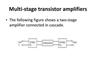
  • 1. Multi-stage transistor amplifiers • The following figure shows a two-stage amplifier connected in cascade.
  • 2. • The overall gain is the product of voltage gain of individual stages. • AV=AV1×AV2 V2/V1×V0/V2=V0/V1 • Where AV = Overall gain, AV1 = Voltage gain of 1st stage, and AV2 = Voltage gain of 2nd stage. • If there are n numbers of stages, the product of voltage gains of those n stages will be the overall gain of that multistage amplifier circuit.
  • 3. Amplifier Consideration • For an amplifier circuit, the overall gain of the amplifier is an important consideration. To achieve maximum voltage gain, let us find the most suitable transistor configuration for cascading. • CC Amplifier Its voltage gain is less than unity. It is not suitable for intermediate stages. • CB Amplifier Its voltage gain is less than unity. Hence not suitable for cascading.
  • 4. CE Amplifier Its voltage gain is greater than unity. Voltage gain is further increased by cascading. The characteristics of CE amplifier are such that, this configuration is very suitable for cascading in amplifier circuits. Hence most of the amplifier circuits use CE configuration.
  • 5. RC Coupling Amplifier • The resistance-capacitance coupling is, in short termed as RC coupling. This is the mostly used coupling technique in amplifiers.
  • 6. Construction of a Two-stage RC Coupled Amplifier • The constructional details of a two-stage RC coupled transistor amplifier circuit are as follows. • The two stage amplifier circuit has two transistors, connected in CE configuration and a common power supply VCC is used. • The potential divider network R1 and R2 and the resistor Re form the biasing and stabilization network. • The emitter by-pass capacitor Ce offers a low reactance path to the signal.
  • 7. • The resistor RL is used as a load impedance. The input capacitor Cin present at the initial stage of the amplifier couples AC signal to the base of the transistor. The capacitor CC is the coupling capacitor that connects two stages and prevents DC interference between the stages and controls the shift of operating point.
  • 8. Frequency Response of RC Coupled Amplifier • Frequency response curve is a graph that indicates the relationship between voltage gain and function of frequency. The frequency response of a RC coupled amplifier is as shown in the following graph. • From the graph, it is understood that the frequency rolls off or decreases for the frequencies below 50Hz and for the frequencies above 20 KHz. whereas the voltage gain for the range of frequencies between 50Hz and 20 KHz is constant. Following equation means that the capacitive reactance is inversely proportional to the frequency. Xc=1/2πfc
  • 9. At Low frequencies (i.e. below 50 Hz) • The capacitive reactance is inversely proportional to the frequency. At low frequencies, the reactance is quite high. The reactance of input capacitor Cin and the coupling capacitor CC are so high that only small part of the input signal is allowed. The reactance of the emitter by pass capacitor CE is also very high during low frequencies. Hence it cannot shunt the emitter resistance effectively. With all these factors, the voltage gain rolls off at low frequencies.
  • 10. At High frequencies (i.e. above 20 KHz) • Again considering the same point, we know that the capacitive reactance is low at high frequencies. So, a capacitor behaves as a short circuit, at high frequencies. As a result of this, the loading effect of the next stage increases, which reduces the voltage gain. Along with this, as the capacitance of emitter diode decreases, it increases the base current of the transistor due to which the current gain (β) reduces. Hence the voltage gain rolls off at high frequencies.
  • 11. At Mid-frequencies (i.e. 50 Hz to 20 KHz) • The voltage gain of the capacitors is maintained constant in this range of frequencies, as shown in figure. If the frequency increases, the reactance of the capacitor CC decreases which tends to increase the gain. But this lower capacitance reactive increases the loading effect of the next stage by which there is a reduction in gain. • Due to these two factors, the gain is maintained constant.
  • 12. Advantages of RC Coupled Amplifier • The following are the advantages of RC coupled amplifier. • The frequency response of RC amplifier provides constant gain over a wide frequency range, hence most suitable for audio applications. • The circuit is simple and has lower cost because it employs resistors and capacitors which are cheap. • It becomes more compact with the upgrading technology.
  • 13. Disadvantages of RC Coupled Amplifier • The following are the disadvantages of RC coupled amplifier. • The voltage and power gain are low because of the effective load resistance. • They become noisy with age. • Due to poor impedance matching, power transfer will be low
  • 14. Applications of RC Coupled Amplifier • The following are the applications of RC coupled amplifier. • They have excellent audio fidelity over a wide range of frequency. • Widely used as Voltage amplifiers • Due to poor impedance matching, RC coupling is rarely used in the final stages.
  • 15. Transformer Coupled Amplifier • We have observed that the main drawback of RC coupled amplifier is that the effective load resistance gets reduced. This is because, the input impedance of an amplifier is low, while its output impedance is high. • When they are coupled to make a multistage amplifier, the high output impedance of one stage comes in parallel with the low input impedance of next stage. Hence, effective load resistance is decreased. This problem can be overcome by a transformer coupled amplifier. • In a transformer-coupled amplifier, the stages of amplifier are coupled using a transformer. Let us go into the constructional and operational details of a transformer coupled amplifier.
  • 16. Construction of Transformer Coupled Amplifier • The amplifier circuit in which, the previous stage is connected to the next stage using a coupling transformer, is called as Transformer coupled amplifier. • The potential divider network R1 and R2 and the resistor Re together form the biasing and stabilization network.
  • 17. • The emitter by-pass capacitor Ce offers a low reactance path to the signal. The resistor RL is used as a load impedance. • The input capacitor Cin present at the initial stage of the amplifier couples AC signal to the base of the transistor. • The capacitor CC is the coupling capacitor that connects two stages and prevents DC interference between the stages and controls the shift of operating point. • This transformer coupling provides good impedance matching between the stages of amplifier. The transformer coupled amplifier is generally used for power amplification.
  • 18. Frequency Response of Transformer Coupled Amplifier • The figure below shows the frequency response of a transformer coupled amplifier. The gain of the amplifier is constant only for a small range of frequencies. The output voltage is equal to the collector current multiplied by the reactance of primary. • At low frequencies, the reactance of primary begins to fall, resulting in decreased gain. At high frequencies, the capacitance between turns of windings acts as a bypass condenser to reduce the output voltage and hence gain. • So, the amplification of audio signals will not be proportionate and some distortion will also get introduced, which is called as Frequency distortion
  • 19. Advantages of Transformer Coupled Amplifier . • The following are the advantages of a transformer coupled amplifier − • An excellent impedance matching is provided. • Gain achieved is higher. • There will be no power loss in collector and base resistors. • Efficient in operation.
  • 20. Disadvantages of Transformer Coupled Amplifier The following are the disadvantages of a transformer coupled amplifier − • Though the gain is high, it varies considerably with frequency. Hence a poor frequency response. • Frequency distortion is higher. • Transformers tend to produce hum noise. • Transformers are bulky and costly.
  • 21. Applications The following are the applications of a transformer coupled amplifier − • Mostly used for impedance matching purposes. • Used for Power amplification. • Used in applications where maximum power transfer is needed.
  • 22. Direct Coupled Amplifier • The other type of coupling amplifier is the direct coupled amplifier, which is especially used to amplify lower frequencies, such as amplifying photo-electric current or thermo- couple current or so. • Direct Coupled Amplifier • As no coupling devices are used, the coupling of the amplifier stages is done directly and hence called as Direct coupled amplifier.
  • 24. • The transistor in the first stage will be an NPN transistor, while the transistor in the next stage will be a PNP transistor and so on. This is because, the variations in one transistor tend to cancel the variations in the other. The rise in the collector current and the variation in β of one transistor gets cancelled by the decrease in the other.
  • 25. Operation • The input signal when applied at the base of transistor T1, it gets amplified due to the transistor action and the amplified output appears at the collector resistor Rc of transistor T1. This output is applied to the base of transistor T2 which further amplifies the signal. In this way, a signal is amplified in a direct coupled amplifier circuit.
  • 26. Advantages and Disadvantages • The advantages of direct coupled amplifier are as follows. • The circuit arrangement is simple because of minimum use of resistors. • The circuit is of low cost because of the absence of expensive coupling devices. • The disadvantages of direct coupled amplifier are as follows. • It cannot be used for amplifying high frequencies. • The operating point is shifted due to temperature variations.
  • 27. Applications • The applications of direct coupled amplifier are as follows. • Low frequency amplifications. • Low current amplifications.
  • 28. Comparisions • Let us try to compare the characteristics of different types of coupling methods discussed till now. • Assignment • ?