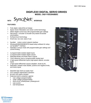
3. ADVANCED MOTION CONTROLS DQ111EE Series
Page 3 of 7
SPECIFICATIONS:
POWER STAGE SPECIFICATIONS DQ111EE20A8BDC
DC SUPPLY VOLTAGE 20…80 VDC
PEAK CURRENT 20A (14.2Arms)
MAXIMUM CONTINUOUS CURRENT 10A (7.1Arms)
MINIMUM LOAD INDUCTANCE 250 μH
SWITCHING FREQUENCY 20 kHz
HEATSINK (BASEPLATE) TEMPERATURE RANGE 0 to 65 ºC, disables at 65 ºC
POWER DISSIPATION AT CONTINUOUS CURRENT 50W
MIN. UNDER VOLTAGE SHUTDOWN 20 VDC
MAX. OVER-VOLTAGE SHUTDOWN 86 VDC
LOGIC SUPPLY VOLTAGE (backup supply) 20…80 VDC, 20W maximum
MECHANICAL SPECIFICATIONS
POWER CONNECTOR: P1 Removable
MOTOR FEEDBACK CONNECTOR: CN4* 15-pin high density female D-sub
I/O CONNECTOR: CN3* 26-pin high density female D-sub
SYNQNETä CONNECTOR: CN1, CN2* 8-pin RJ45
SIZE 5.22 x 3.52 x 1.42 inches
132.5 x 89.5 x 35.9 mm
WEIGHT
* Mating connectors are not included.
Sold & Serviced By:
ELECTROMATE
Toll Free Phone (877) SERVO98
Toll Free Fax (877) SERV099
www.electromate.com
sales@electromate.com
4. ADVANCED MOTION CONTROLS DQ111EE Series
PIN FUNCTIONS:
P1 - Motor and Power Connector:
CAUTION: the pin numbering of the mating connector is different from the numbering of the drive connector.
In the table below, the second column corresponds to the drive pin numbering (silkscreen). The second to last
column corresponds to the mating connector pin numbering.
Commutation sensor inputs. Internal
2K pull-up to +5VDC. Can be used
with single ended or differential Hall
sensors. I
Page 4 of 7
DRIVE
CONN. PIN NAME DESCRIPTION I/O PIN
MATING
CONN.
1 MA Motor phase A O 6
2 MB Motor phase B O 5
3 MC Motor phase C O 4
4 HV IN
DC motor and power input. This input is used
to supply power to the motor and drive logic
circuitry.
I 3
5 GND Ground GND 2
P1
6
LOGIC
PWR
Logic supply input. This input can be used to
supply power to the drive logic circuitry only.
Effective only when the voltage applied to pin
P1-4 is lower then the voltage applied to P1-6.
I 1
CN4 - Motor Feedback Connector:
CONNECTOR PIN NAME DESCRIPTION I/O
1 +Hall A I
2 +Hall B I
3 +Hall C
Encoder Input. For single
4 MOT ENC A+ I
5 MOT ENC A-Differential
ended encoder signals, leave the A–
terminal open. I
Encoder Input. For single
6 MOT ENC B+ I
7 MOT ENC B-Differential
ended encoder signals, leave the B–
terminal open. I
Encoder Input. For single
8 MOT ENC I+ I
9 MOT ENC I-Differential
ended encoder signals, leave the I–
terminal open. I
10 -Hall A* See CN4-1. Leave open in case of
single ended Hall sensors.
I
11 -Hall B* See CN4-2. Leave open in case of
single ended Hall sensors.
I
12 SGND Signal ground SGND
13 +5V OUT +5V @ 250mA max. Short-circuit
protected.
O
14 Reserved
CN4
15 -Hall C* See CN4-3. Leave open in case of
single ended Hall sensors.
I
Sold & Serviced By:
ELECTROMATE
Toll Free Phone (877) SERVO98
Toll Free Fax (877) SERV099
www.electromate.com
sales@electromate.com
5. ADVANCED MOTION CONTROLS DQ111EE Series
Page 5 of 7
CN3 – I/O Connector:
CONNECTOR PIN NAME DESCRIPTION I/O
1 USER OUTPUT 0 Programmable digital output. Isolated,
24VDC, referenced to USER GND
O
2 USER OUTPUT 1 Programmable digital output. Isolated,
24VDC, referenced to USER GND
O
3 USER GND Ground reference for user outputs and
inputs.
GND
4 NODE ALARM SynqNet network error. Isolated,
24VDC, referenced to USER GND
O
5 BRAKE
Brake output, controlled directly via
SynqNet. Isolated, 24VDC, referenced
to USER GND
O
6 AGND Analog ground AGND
7 + DIFF. INPUT 0 Differential input. 5V TTL., non-isolated.
I
8 - DIFF. INPUT 0
Programmable function: capture I
9 OUTPUT PULL-UP 5K Pull-up for user outputs. I
10 NODE DISABLE
Node disable input. Isolated, 24VDC
range. Referenced to sensor common
(SENSCOMMON).
I
11 LIMIT +
Positive limit input. Isolated, 24VDC
range. Referenced to sensor common
(SENSCOMMON).
I
12 LIMIT -
Negative limit input. Isolated, 24VDC
range. Referenced to sensor common
(SENSCOMMON).
I
13 HOME
Home switch input. Isolated, 24VDC
range. Referenced to sensor common
(SENSCOMMON).
I
14 USER INPUT 0 Programmable digital input. Isolated,
24VDC, referenced to USER GND
I
15 USER INPUT 1 Programmable digital input. Isolated,
24VDC, referenced to USER GND
I
16 SENSCOMMON
Sensor common. Used with E-stop, limit
+, limit -, and home inputs. Can be used
as a ground reference or as a pull-up
for these inputs.
COMMON
17 + DIFF. INPUT 1 Differential input. 5V TTL., non-isolated
I
18 - DIFF. INPUT 1
Programmable function: capture I
19 SGND Digital ground SGND
20 + DIFF. OUTPUT 0 Differential output. 5V TTL., non-isolated.
O
Programmable function:
21 - DIFF. OUTPUT 0
step&dir, divide-by-N O
Differential output. 5V TTL., non-isolated.
22 + DIFF. OUTPUT 1 O
Programmable function:
23 - DIFF. OUTPUT 1
step&dir, divide-by-N O
24 +ANALOG IN Programmable, differential analog input,
I
25 -ANALOG IN
+/- 10V range, 14-bit. I
CN3
26 AGND Analog ground. AGND
Sold & Serviced By:
ELECTROMATE
Toll Free Phone (877) SERVO98
Toll Free Fax (877) SERV099
www.electromate.com
sales@electromate.com
6. ADVANCED MOTION CONTROLS DQ111EE Series
Page 6 of 7
CN1 – SYNQNETä INTERFACE:
CONNECTOR PIN NAME DESCRIPTION I/O
1 RD+ I
100BaseT receiver
2 RD-
I
3 TD+ O
100BaseT transmitter
6 TD-
O
CN1
4, 5,
7, 8
N/C Not connected
CN2 – SYNQNETä INTERFACE:
CONNECTOR PIN NAME DESCRIPTION I/O
1 TD+ O
100BaseT transmitter
2 TD-
O
3 RD+ I
100BaseT receiver
6 RD-
I
CN2
4, 5,
7, 8
N/C Not connected
ORDERING INFORMATION:
Standard model: DQ111EE20A8BDCX
X indicates the current revision letter.
Sold & Serviced By:
ELECTROMATE
Toll Free Phone (877) SERVO98
Toll Free Fax (877) SERV099
www.electromate.com
sales@electromate.com
7. ADVANCED MOTION CONTROLS DQ111EE Series
Page 7 of 7
MOUNTING DIMENSIONS:
Sold & Serviced By:
ELECTROMATE
Toll Free Phone (877) SERVO98
Toll Free Fax (877) SERV099
www.electromate.com
sales@electromate.com