
Recommended
Recommended
More Related Content
Similar to lc6000-overview_2c-features-sequence-of-operation-study-guide-7-1-2019.pdf
Similar to lc6000-overview_2c-features-sequence-of-operation-study-guide-7-1-2019.pdf (20)
Recently uploaded
Recently uploaded (20)
lc6000-overview_2c-features-sequence-of-operation-study-guide-7-1-2019.pdf
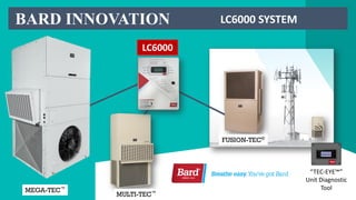
- 1. FUSION-TEC® MULTI-TEC™ MEGA-TEC™ “TEC-EYE™” Unit Diagnostic Tool LC6000 BARD INNOVATION LC6000 SYSTEM
- 2. LC6000 Controller Capabilities 1 Controller 1 to 14 units 1 to 3 zones / allows 3 diff temp and humidity settings Extra temp only sensor in zone 1 Up to 3 humidifiers, 1 in each zone Device input terminals for emergency shut down Device input terminals for emergency ventilation by zone INNOVATION SLIDE 1 0F 2
- 3. LC6000 Controller Capabilities Mix and match units with & without economizer, varying number of stages & different models There are 9 Alarm notification outputs for network operating center (NOC) Multiple actions and corrections made by the controller during alarming conditions to keep the temperature stable and/or equipment and operators safe Compatible with: FUSION-TEC, MULTI-TEC and the MEGA-TEC MORE…..
- 4. Communication EMI Filters Programmable Logic Controller “TEC-EYE™” Diagnostic Tool LC6000 Series Controller Remote Temperature / Hum. Sensor with 35 ft. cable INCLUDED IN THE BOX
- 5. EEV Manual Adjustment Service Tool Part #2151-021 TEC-EYE SERVICE TOOL 8301-059 TEMP / HUMIDITY SENSOR(PN/8403-079) OPTIONAL COMPONENTS FOR THE MEGA-TEC “SYSTEM’ Part number Description Included with lV1000 8301-055 EMI Ferrite Filter 2 included 8403-079 Remote Temp/Humidity Sensor 1 incl / up to 2 more opt. 8301-058 Remote Temperature Sensor Optional 8301-059 TEC-EYETM (service tool) w/5’ cable Included 113-140 Bottom Mounting Bracket Optional 8301-053 Large Display Service Tool Optional 2151-021 EEV manual Adj. Service Tool Optional Large Display Service Tool Part #8301-053 Communication EMI Filters REMOTE TEMP SENSOR(PN/8301-058)
- 6. LC6000 controllers with 3 Zones Zone 1 Zone 3 Zone 2 LC6000 Controller SEQUENCE OF OPERATION: The LC6000 monitors the individual zone temperatures. The LC6000 uses a PID loop to match the resources to the load, the process functions similar to the cruise control on your car. You may use from 1 to 3 zones and they can have different settings. FUSION-TEC® MULTI-TEC™ MEGA-TEC™
- 7. The LC6000 (shelter controller) is manufactured with two user selectable “profiles” that can be turned on based on the application and preferences of the end user. Note: The PROFILE selection is made for ALL ZONES UTILIZED (1 TO 3). You may not select one profile for zone one and the second profile for the other zones. One profile for one controller. Rotation (FIFO, LIFO) or DEMAND (TEMP. PRIORITY) SHELTER CONTROLLER Operation Details
- 8. Controller Profiles: Units run in a FIFO, LIFO OR DEMAND. Select“MAX RUN” FOR EACH ZONE LC6000 controllers with 3 Zones Zone 1 Zone 3 Zone 2 LC6000 Controller 81 77 78 73 79 DEMAND PROFILE 77.6 is avg. temp
- 9. LC6000 controllers with 3 Zones Zone 1 Zone 3 Zone 2 LC6000 Controller Profiles: Units run in a Rotational (FIFO) Schedule or DEMAND (temperature priority). All units are in rotation. The PID loop process will match the resources to the load and only bring on the required units. If a unit is locked out OR not cooling to capacity and the resource is required, one of your N+ units will be cycled on. ROTATION (N+) Zone 1 Lead Next on Spare
- 10. LC6000 controllers with 3 Zones Zone 1 Temperature /Humidity Sensor Zone 3 Zone 2 Humidifier Humidifier Temperature /Humidity Sensor Temperature/Humidity Sensor Temperature Sensor Zones can be set to different temperature and humidity settings. LC 6000 CONTROLLER LC6000 Controller INNOVATION INNOVATION
- 11. Because the units are cycled on to match the load, more than 1 unit may be called on simultaneously, it is necessary to build in a delay to prevent extraordinary current inrush on compressor start up. Default is 5 seconds. For cooling, when the PID calls for cooling there is a time delay between stages. Compressor Delay Logic SHELTER CONTROLLER Operation Details
- 12. LC6000 controllers with 1 Zone Zone 1 NOTE: Units you have added for an N+ application will only be called on if required. For example; if there are 2 units required, with N+ you install 3, all 3 will be in rotation. LC6000 Controller Profile setting is “ROTATION” or “DEMAND”. Operation Details
- 13. Zone 3 Zone 2 LC6000 Controller Zone 1 LC6000 UPDATE: Select max Number of Units to RUN
- 14. 1. The shelter control monitors the zone temperature measuring the temperature at the remote sensor(s) and each of the unit return air sensors in the zone providing feedback based on average temperature. Note: Sensors used are selectable Unit Rotation N+ 2. The shelter control signals the number of stages to turn on proportional to the difference between the desired temperature (setpoint) and the actual temperature. If free cooling is available, all of the economizers are considered first in the resource allocation. 3. Units will rotate in: lead, next on, next on, and so on, providing more equal wear. Operation Details
- 15. STAGING SEQUENCE With 5 units in a Zone And “max number of mechanical cooling units to run set at 4” Sequence of Operation: The staging sequence will use all economizers (when available) before enabling mechanical cooling. Example: Econ 1, Econ 2 , Econ3, Econ 4, Econ 5 Comp 1, Comp 2, Comp 3, Comp 4. (5 Idle) Units will rotate into lead position on a 7 day basis (adj.) and the switch happens at midnight. Sequencing units off is defaulted to FIFO, FILO is an option. SHELTER CONTROLLER Operation Details
- 16. The Shelter Controller can be configured to control up to 3 humidifiers with relay outputs. Humidification: If the humidity level is below 45% RH the Shelter Controller will enable humidification for that zone. Once the humidity level rises to 55%RH the humidification for that zone will be disabled. Dehumidification: If the humidity level rises to 70% RH in the shelter, the LC disable the economizer for that zone. If the RH reaches 80% active Dehum begins. Humidifier Configuration & Logic SHELTER CONTROLLER
- 17. 1. Electric Re-heat Dehum: MULTI-TEC™ 2. Mechanical Reheat Dehum: MULTI-TEC™ 3. Cycling Reheat Dehum: FUSION-TEC® 4. Electric Re-Heat Dehum: MEGA-TEC™ (MEGA-TEC DEHUM IS AVAILABLE) SELECTED IN LC6000 TO MATCH UNIT OPTION Dehumidification Configuration & Logic LC6000 UPDATE: Dehum Selection
- 18. Dehum Configuration & Logic Dehumidification These units are equipped with Balanced Climate™ 1. When the indoor humidity reaches 70% (default, adjustable) the High Sensible mode and the economizer will become disabled. The unit will enter "Balanced Climate“ mode 2. Balanced Climate mode is indicated in the display as “passive” mode. The blower will slow down and allow the coil to remove the maximum amount of moisture, the unit will exit Balanced Climate™ mode when the cooling call terminates or the indoor humidity reaches 60%. 3. At 80% active Dehum is enable. SHELTER CONTROLLER
- 19. 1. Low Temperature Alarm output avail Alarm only 2. High Temperature Alarm 2 output avail Emergency Cooling-All allowed units on & Ventilation 3. Emer. Shutdown Alarm output avail All functions stop 4. Generator Run Alarm output avail Limit units available to run user selectable *1 5. Emer. Ventilation Alarm output avail Ventilates zone(s) selected by user *2 6. Zone 1 HVAC Fail Alarm output avail Switch to “next on” (HP or LP only) 7. Zone 2 HVAC Fail Alarm output avail Switch to “next on” (HP or LP only) 8. Zone 3 HVAC Fail Alarm output avail Switch to “next on” (HP or LP only) 9. Humidity Alarm output avail Alarm only Shelter Controller alarms available for shelter communications to NOC Alarm Condition Level of output Action *2. User can disable ventilation by zones for Emer. Vent event. Default is Enable all zones to ventilate. Note: There are other alarms kept at a local level and not reported out. Notes: *1. User enable/disable by unit in order to stay below available generator watts. All are disabled by default and units selected to run must be enabled at set up.
- 20. LC6000 : AVAILABLE ALARMS NOTE: If no temperature sensors are detected by the controller for a given zone, that zone alarm output will be activated AND since there is no reading, heating and cooling stop. THIS IS NOT CONFIGURABLE! NOTE: Power Loss alarm is also activated by communication loss. If power or communication is lost, the “power loss” alarm is activated.
- 21. Unit alarms that can be attached to the HVAC FAIL alarm or “ZONE ALARMS” LC6000 UPDATE: AVAILABLE ALARMS These alarms are sent out through the HVAC Zone 1, 2 or 3 NOC output. These are alarm only and only High Pressure and Low Pressure actually lock the unit out.
- 22. LC6000 controllers with 3 Zones Zone 1 Temperature /Humidity Sensor Zone 3 Normally Open Contacts Zone 2 Humidifier Humidifier Humidifier Temperature /Humidity Sensor Temperature /Humidity Sensor Temperature Sensor Zone 3 can be set to different temperature and humidity settings Zone 2 can be set to different temperature and humidity settings LC 6000 CONTROLLER LC6000 Controller INNOVATION Sequence Review
- 23. The controller itself can be installed in any indoor location that is suitable, preferably at eye level. There are (4) mounting holes in the LC6000. Because the controller utilizes a remote temperature sensor as opposed to one located in the controller box, the controller can be mounted anywhere that is accessible without regards to temperature. Installing Remote Indoor Temperature/Humidity Sensor(s) One remote indoor temperature/humidity sensor is included with the controller. This sensor must be installed for proper operation. Use shielded cable to mount the temperature/humidity sensor in a location least likely to be affected by open doors, rack-mounted fans, radiant heat sources, etc. Locating the sensor between both return grilles is often the best location, but every installation is unique. Location height should be approximately 48" above the floor. The sensor should be installed on a 4" by 4" junction box to allow for control wire conduit (see Figure 1.16). NOTE: Because this controller can control multiple units (up to 14) in 3 different zones using wet bulb, enthalpy or dry bulb only, a plan should be developed for the placement of each of the zone sensors to locate them where they will give the most accurate representation of the area you are conditioning. Mounting & Location NOTE: Temp/Humidity wires can not exceed 30 meters
- 24. SENSOR LOGIC The LC6000 will average the sensor values for the zone based on user selected options. You select LC6000 ONLY, ALL or UNITS W/BLOWER set to continuous. Installing Remote Indoor Temperature Sensor INNOVATION SHELTER CONTROLLER
- 25. Shelter Inputs Power supply Connections PLC board SHELTER CONTROLLER
- 26. A reliable earth ground must be connected in addition to any grounding from conduit. Attach earth ground to dedicated lugs on side of controlle box. Failing to ground the controller box properly could result in damage to the equipment. SHELTER CONTROLLER
- 28. Trusted Protection. Smart Innovations. Rugged Reliability. Two (2) CORRECTLY Sized AC Circuit Breakers for the Shelter AC Breaker Box (see Electrical Table) High-Voltage Wire of Various Gauges (see Electrical Table) 18 Gauge, 3-Wire, Non-Shielded Cable for Smoke/Hydrogen Detectors, Generator Relay CAT 6 Ethernet Cable of Field-Determined Length (For Remote Access, if applicable) Miscellaneous Rigid/Flex Conduit & Ftg’s, Junction Boxes, Wire Connectors, Supports NECESSARY MATERIALS & TOOLS: (CONT.) Electrical Supplies INNOVATION SHELTER CONTROLLER
- 29. Communication wiring Communication Wire: Recommended 18ga. 2-Wire Shielded Cable with drain. 2 m (6.5 Ft) max for the TEC-EYE or PGD display (Display) 500 m (1640 Ft) max for shielded communication wire. (Modbus) 100 m (328 Ft) max for Ethernet INNOVATION SHELTER CONTROLLER NOTE: 5 WIRE SHIELDED CABLE FOR THE REMOTE TEMP/HUMIDITY SENSORS CANNOT EXCEED 30 METERS
- 30. Control Terminal Block Connections Be sure cable connections on remote sensor match the numbers on the controller as listed to the left NOTE: The colored circles are only calling out the landing points for the communication wires from the sensor to the term board and have nothing to do with wire colors, that will vary by brand of wire. Terminals
- 31. LC6000 INSTALLATION Be sure that all terminals are connected as shown in the slides above and below. LC CONTROLLER
- 33. Line voltage connection 25 Development Emergency Vent Input Emergency Vent Common Emergency shutdown Input Emergency shutdown Common Control Terminal Block Connections Note: Emergency shutdown can be used for smoke or any other detector to shut the wall units down Note: Emergency Ventilation can be used for hydrogen or any other detector to Ventilate the zone or zones
- 34. Line voltage 30 Development NOC OUTPUTS HUM Comm Emer. Inputs Temp & Hum Sensors Control Terminal Block Connections Emergency shutdown Output Emergency shutdown Common Emergency Ventilation Output Emergency Ventilation Common
- 35. LC6000 UPDATE 2019 LC6000 INSTALLATION Slide 1 of 2 RESERVED NOTE: THE BARD GUARD™ IS SCHEDULED FOR Q4/2019 FOR THE MEGA-TEC AND IS CURRENTLY AVAILABLE FOR THE FUSION-TEC. (Bard Guard details are in the FUSION-TEC® section) OPTIONAL Remote OUTDOOR Temp & Humidity Sensor
- 36. LC6000 INSTALLATION LC6000 UPDATE 2019 Slide 2 of 2
- 37. 9. Communications Connection SHELTER CONTROLLER Control Terminal Block Connections
- 38. Connect the communication wiring from the wall-mount units to the controller in the manner shown in a “daisy chain” configuration. The communication wire should be 2-wire, 18 gauge shielded cable with drain. Any color can be used. Be sure to match "+" and "-" symbols on controller terminal blocks to prewired unit control terminal block. Attach communication wire filters as shown in end of each run Do not run communication wiring in same conduit as supply wiring. Route communication wiring and power supply wiring in their own separate conduits. Daisy Chain Configuration INNOVATION
- 39. Notice the line filter locations. LC6000 can be in any position in the daisy chain. The chain is never closed, there is always a beginning and an end. Daisy Chain Configuration
- 41. NOTE: LINE FILTER MUST BE INSTALLED ON ENDS OF DAISEY CHAIN CIRCUIT Daisy Chain Configuration
- 42. General Information: • The controller is completely programmed at the factory. However, there are many variables for each application and most applications will require field set-up. • Default setpoints and their ranges are easily viewed and adjusted from the controller display. • The program and operating parameters are permanently stored on FLASH-MEMORY in case of power failure. LC6000 CONTROLLER USER INTERFACE CONTROLLER INTERFACE ACRONYMS • MAT – Mixed air temperature • RAT – Return air temperature • OAT – Outdoor air temperature • OAH – Outdoor air humidity • Zone 1* – Space temperature and humidity • Zone 2* – If sensor connected • Zone 3* – If sensor connected • Blower – Indoor Blower Status • Damper – Free cooling damper position status • C1 – Compressor activate status • H1 – Heater Stage 1 status • H2 – Heater Stage 2 status • ODP – Calculated outdoor dew point • FC – Free cooling status • RN – Component run time in minutes in last hour • ST – Number of start requests in last hour NOTE: * Only on LC6000 interface NOTE: Digital refers to on/off, analog is a variable input INNOVATION SYSTEM INSTALL SETUP & TEST
- 43. SETUP SYSTEM & VERIFY OPERATION INNOVATION 1. Address the Wall Unit 2. Select the Zone (1 ,2, or 3) 3. Execute a “Run Test” Of Each Unit 4. Set LC6000 Date And Time 5. Configure Sensors 6. Enter the Total Units 7. Verify Units Are Online 8. Completion Review / System Is In Operation Once units and controller have been completely installed and electrical connections have been terminated Correctly there are eight setup steps that must be completed to bring the system “ON-LINE” NOTE: THESE STEPS WILL BE COVERED IN THE “SYSTEM SET UP” VIDEO 3 of LC6000 section
- 45. Optional Remote access communication Web Card Communication: If applicable, connect the LC6000 controller Ethernet port to an existing Ethernet card in the shelter. This will allow remote access, via Ethernet, to many functions on the controller LC6000 Controller
- 46. Eye-Tec Diagnostic Tool storage TEC-EYE Storage: Before leaving the site, attach the TEC-EYE Diagnostic Tool (using the integral magnets) and cable to the interior of the cabinet, and securely lock the controller door. LC6000 Controller INNOVATION
- 47. www.bardhvac.com
- 48. Specifically engineered, intelligently manufactured QUESTIONS???????? Contact: Rick.Downie@BardHVAC.com
- 49. BARD INNOVATION FUSION-TEC® MULTI-TEC™ MEGA-TEC™ Video Two - Installation LC6000 Thank you for choosing Bard !!!!!