This document discusses assembly modeling concepts including:
- The differences between part and assembly modeling and common assembly modeling approaches like bottom-up and top-down.
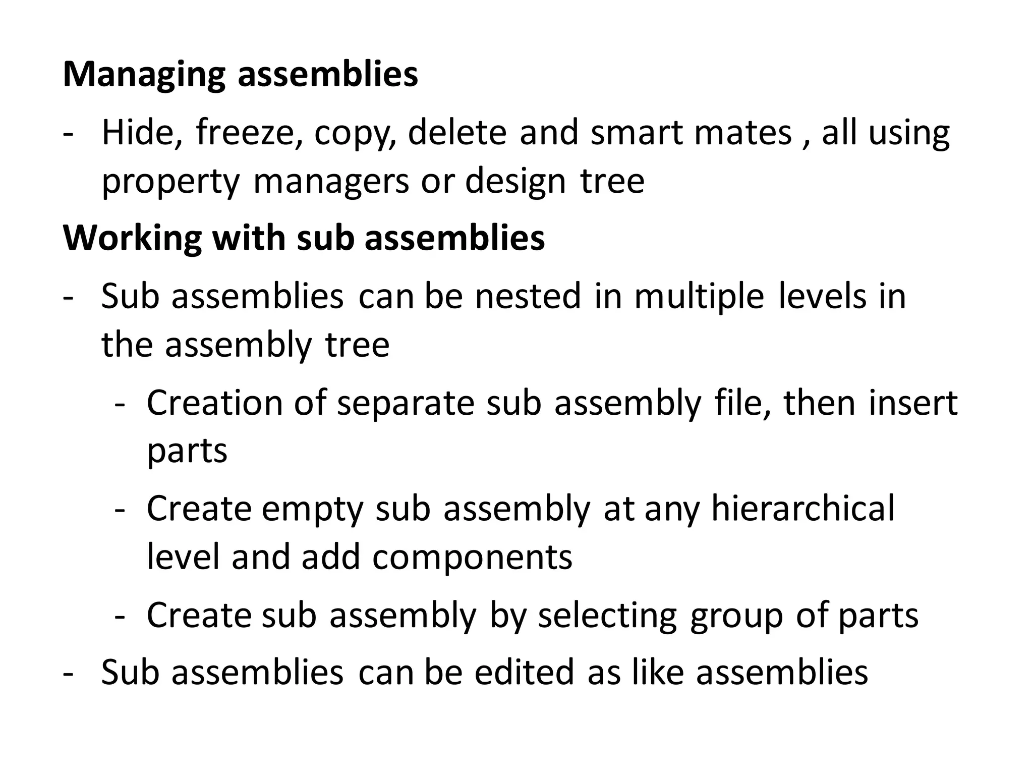
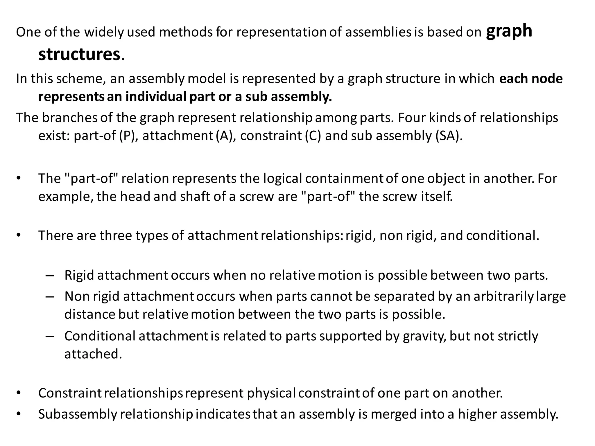
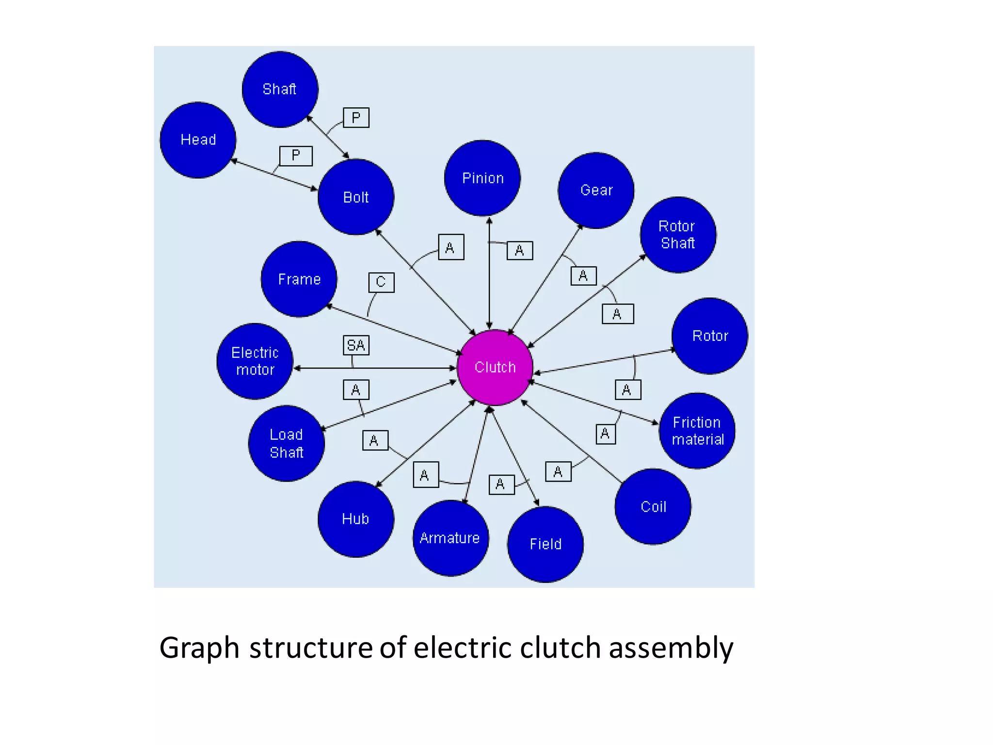
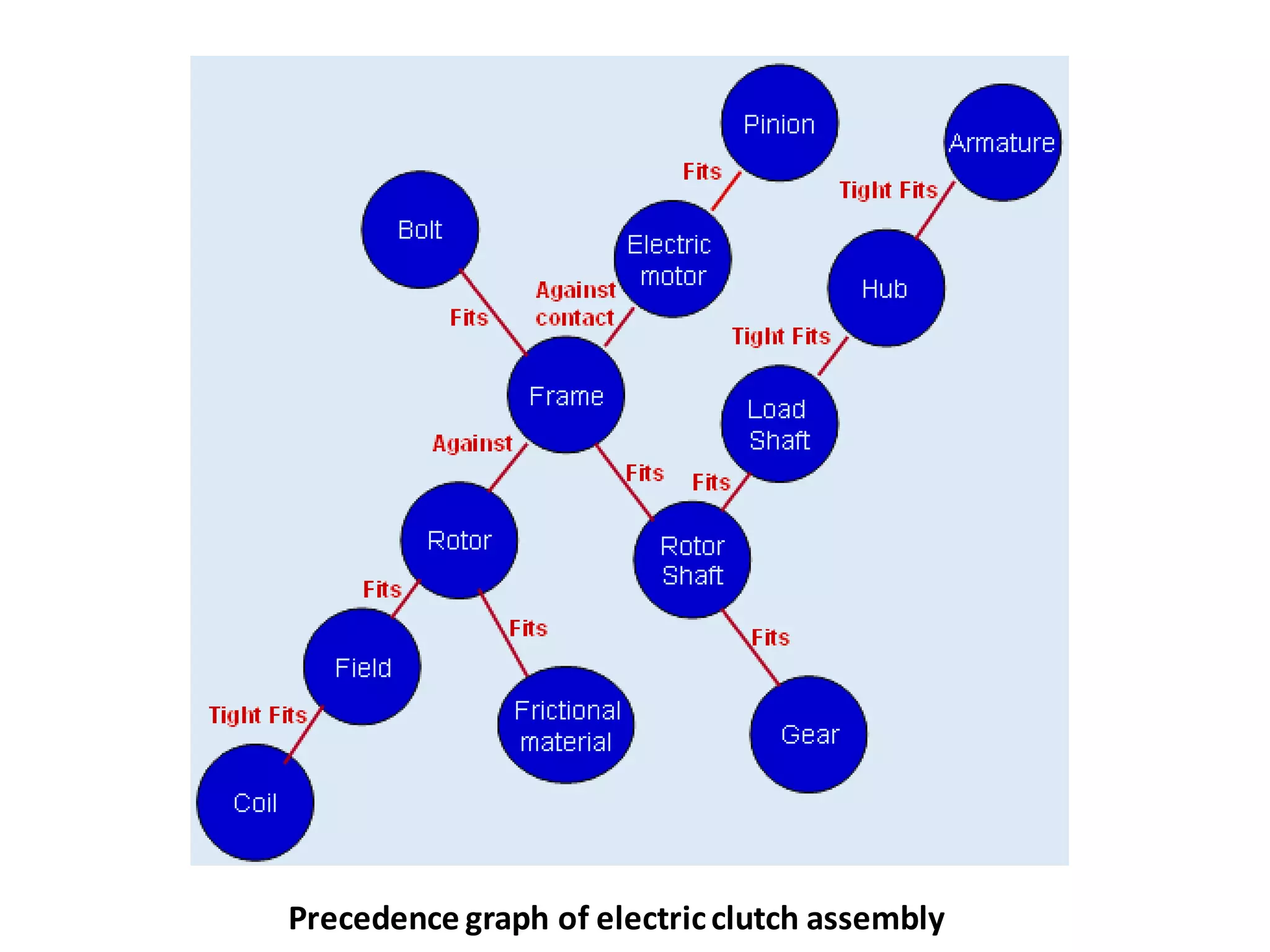
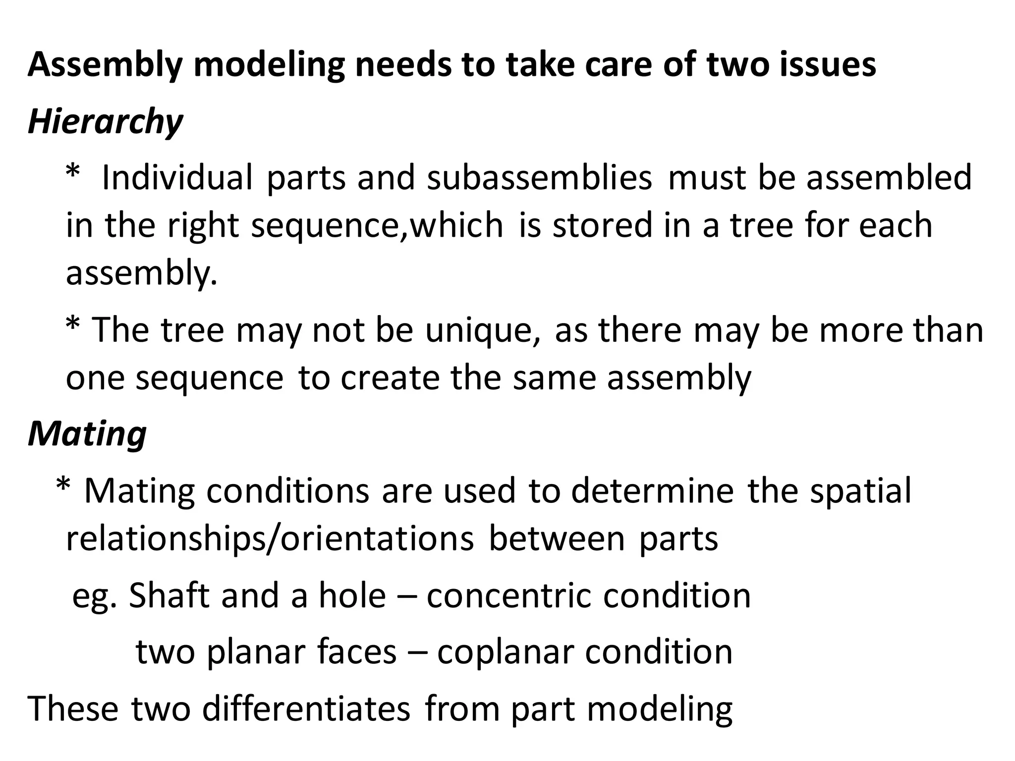
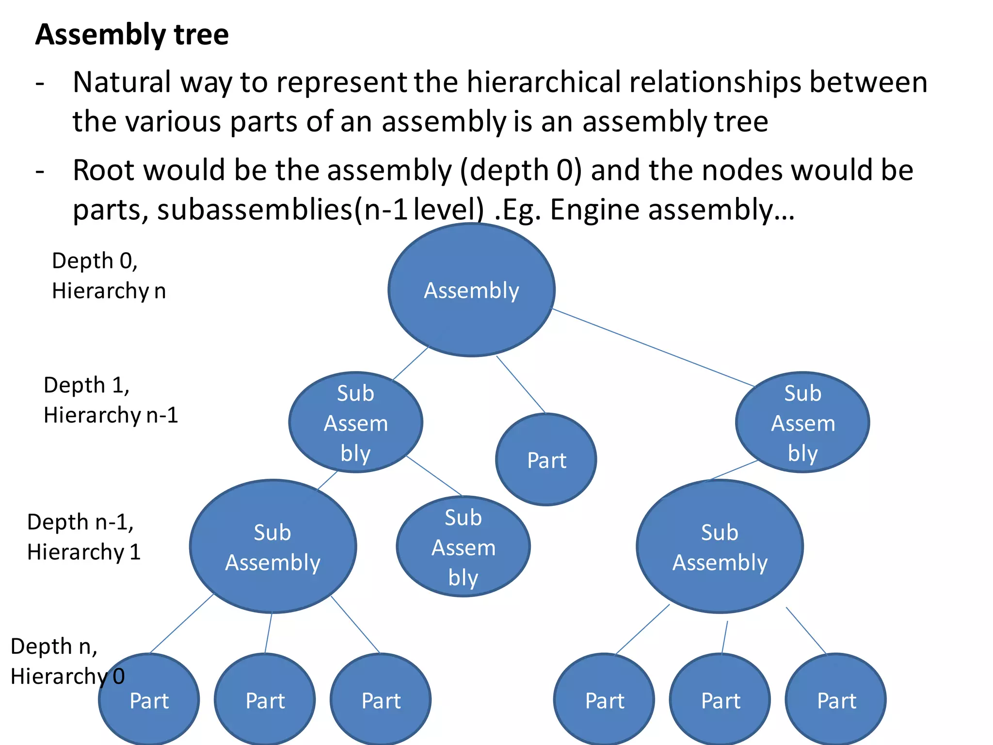
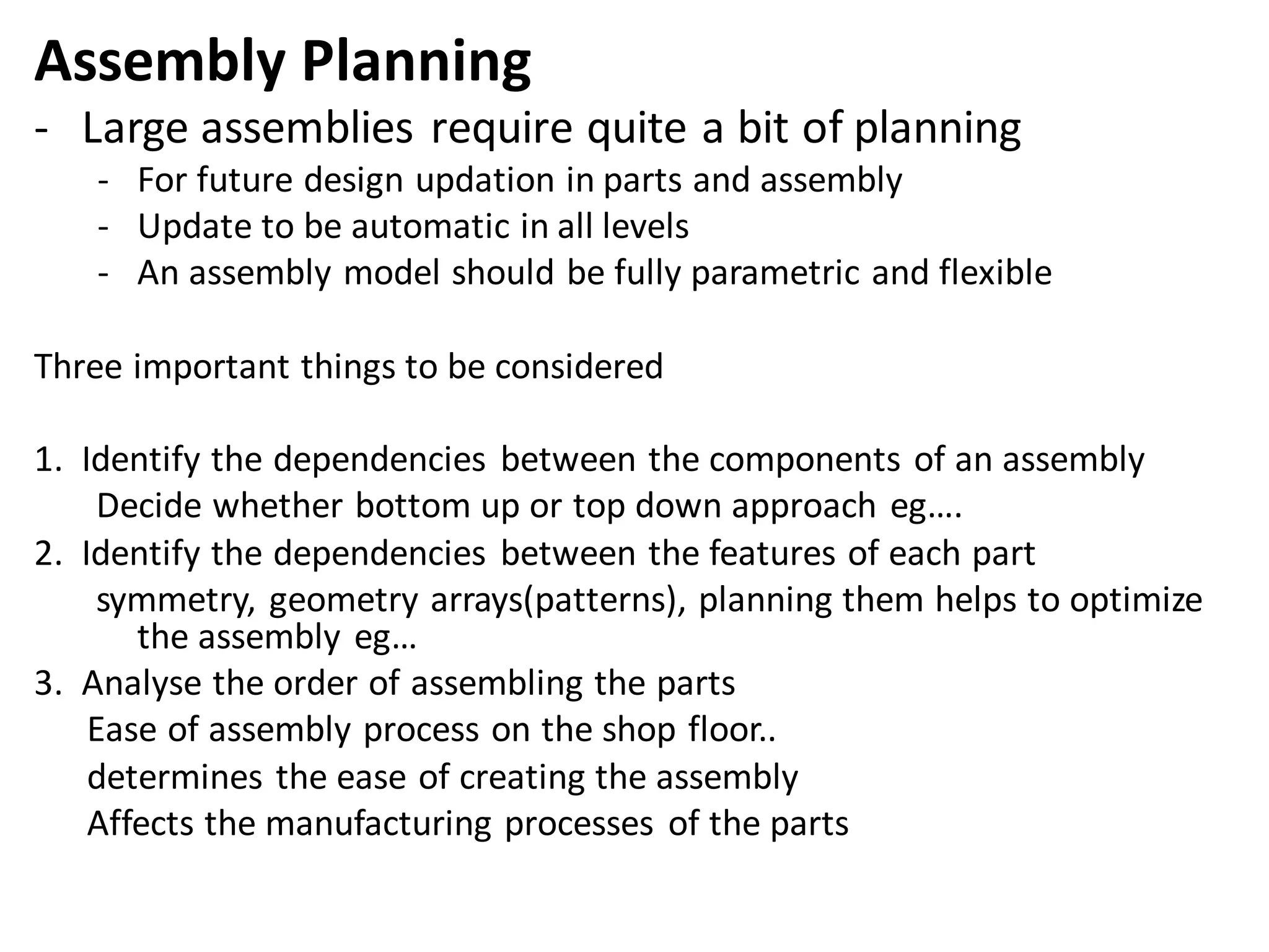
- Key aspects of assembly modeling like hierarchy, mating conditions, assembly trees, and managing large assemblies.
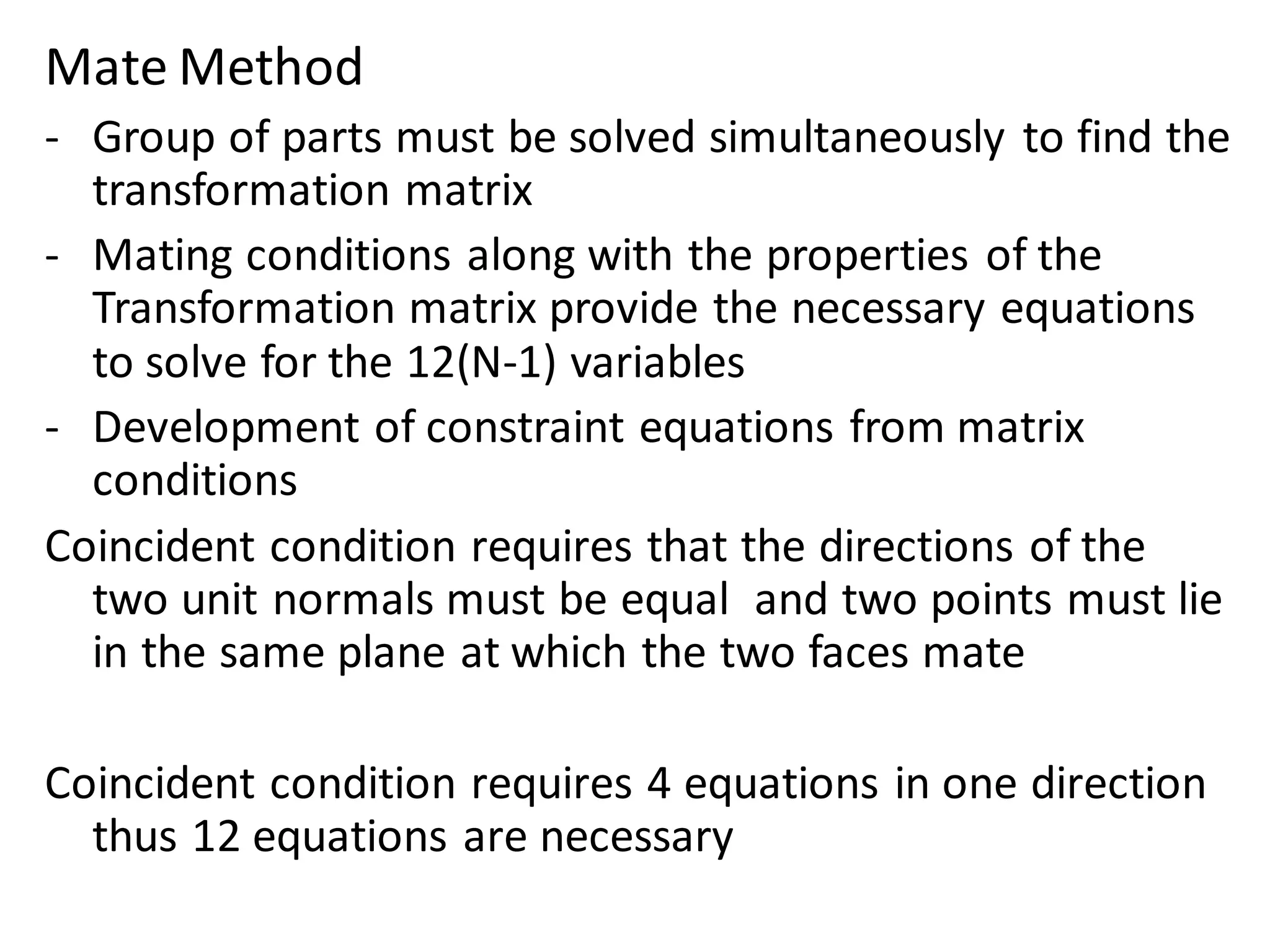
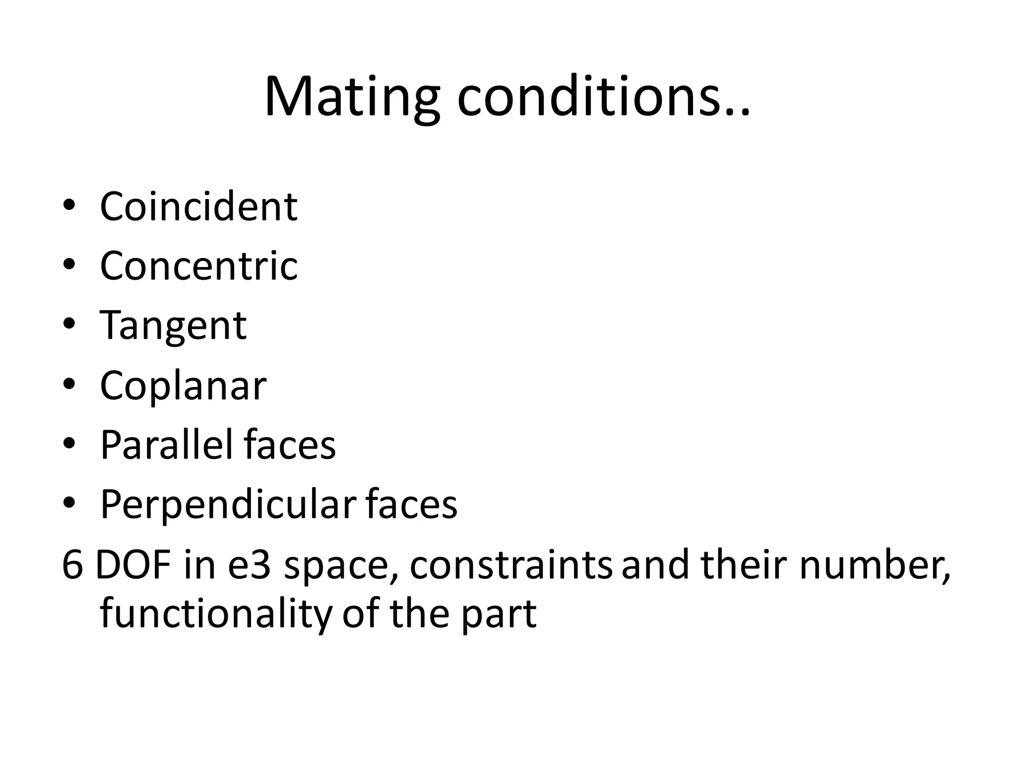
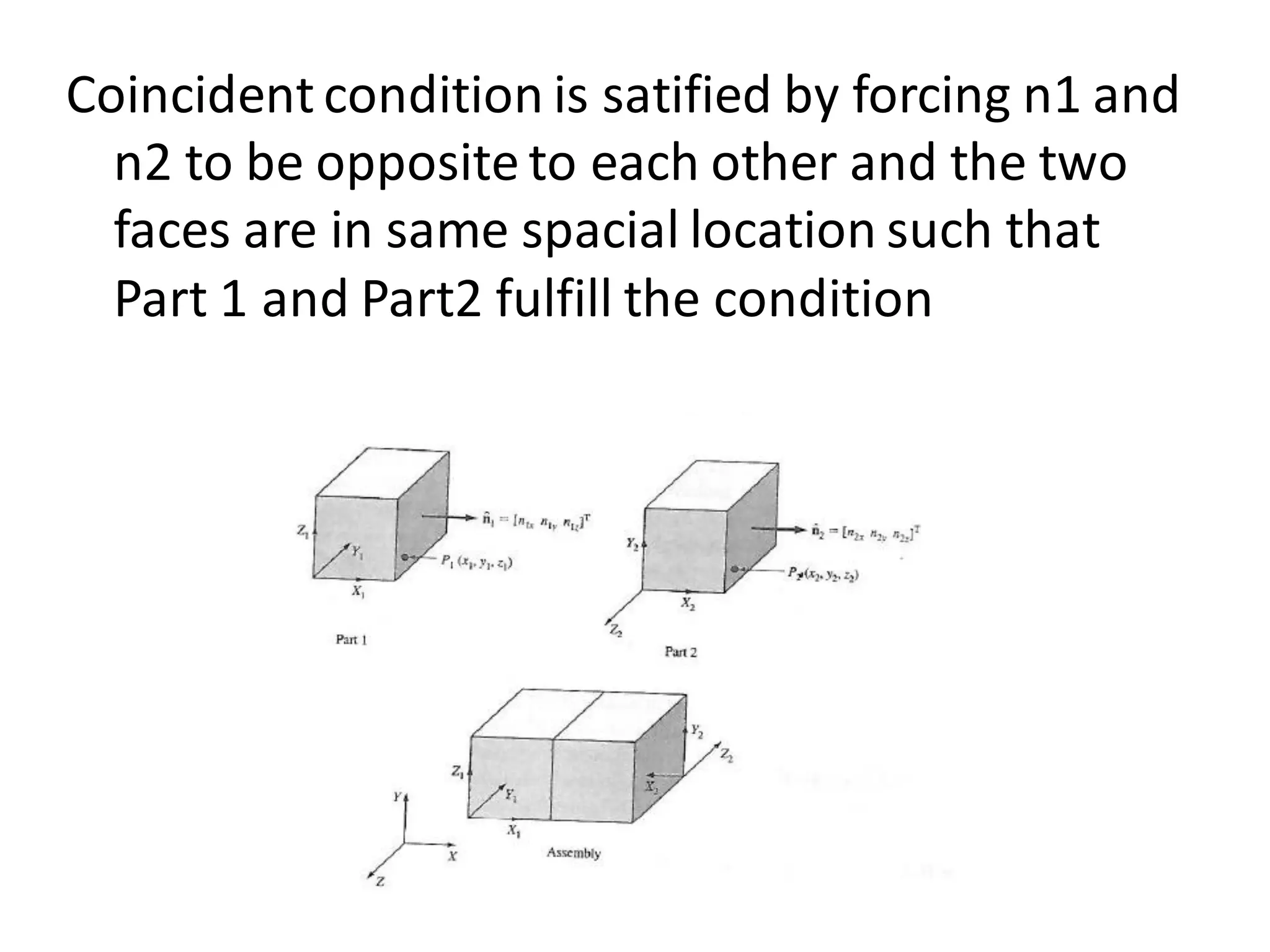
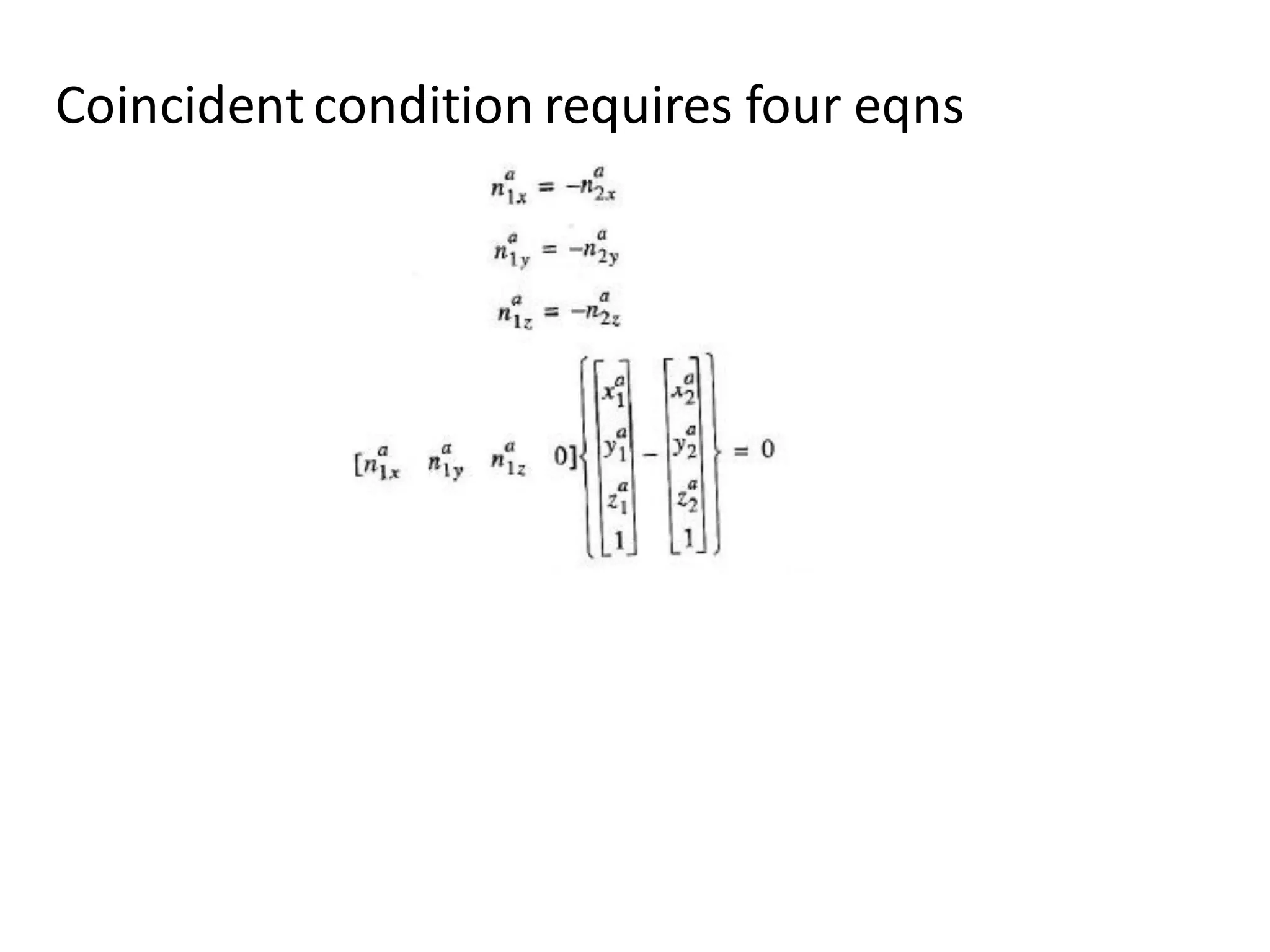
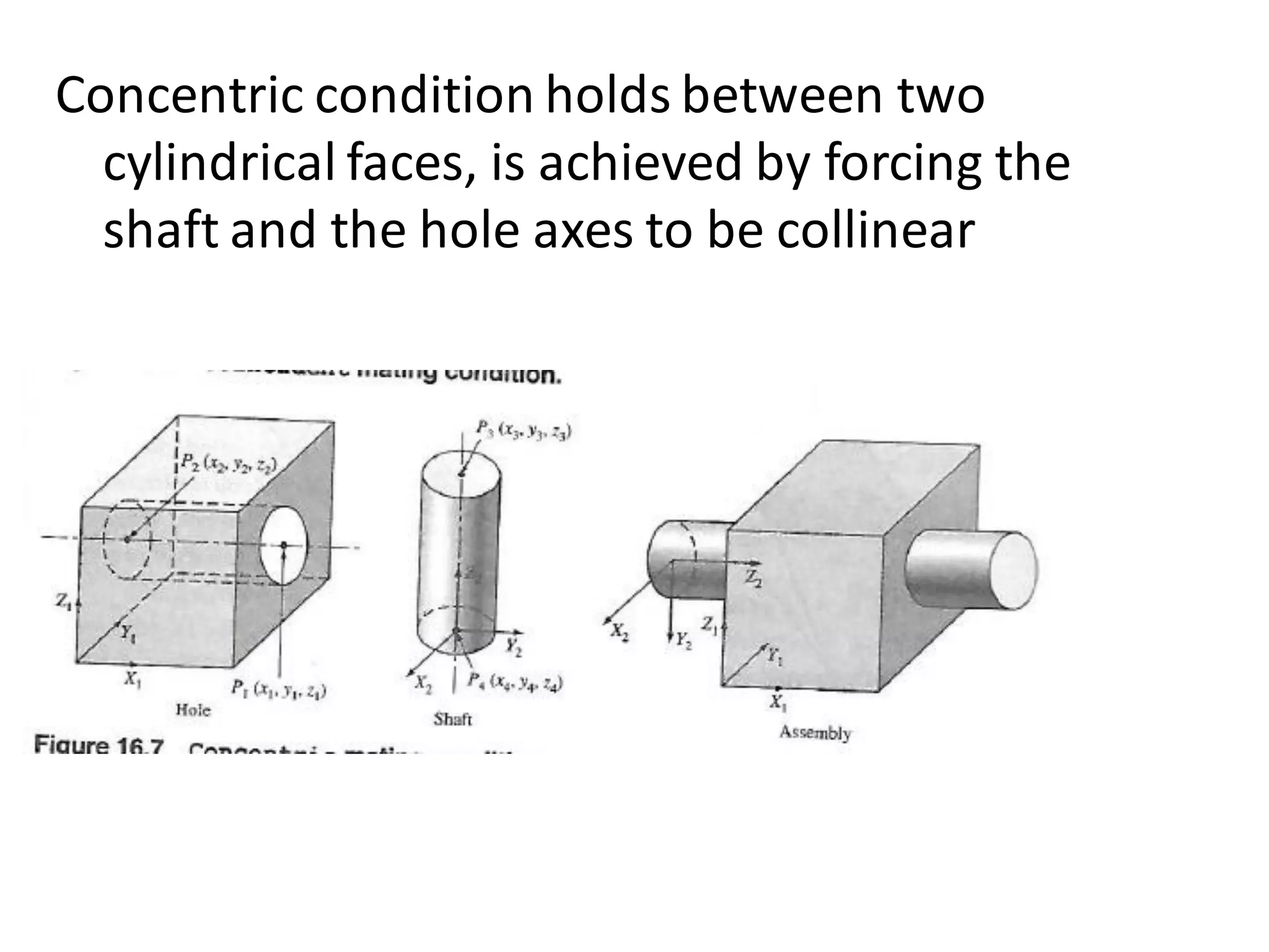
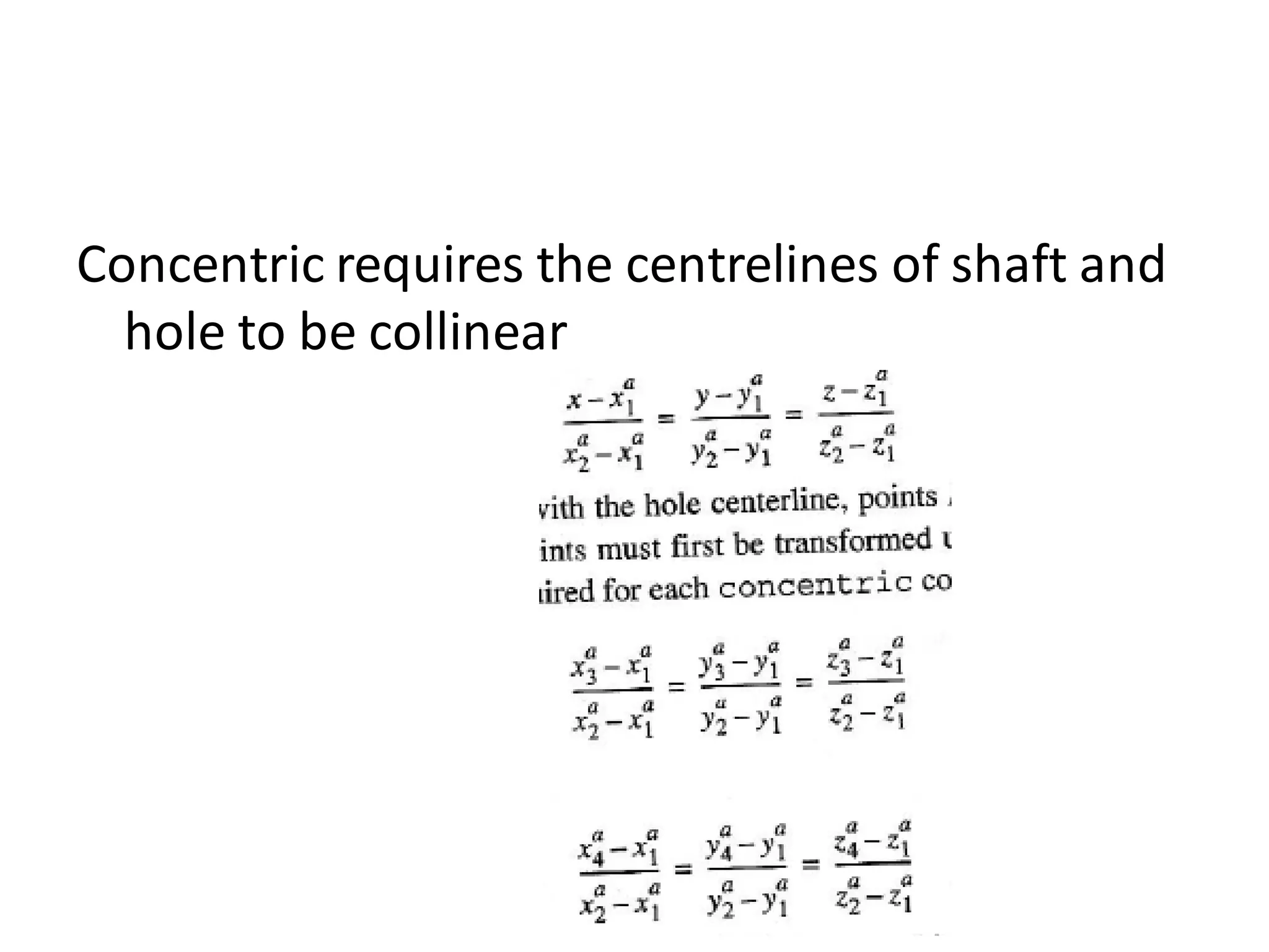
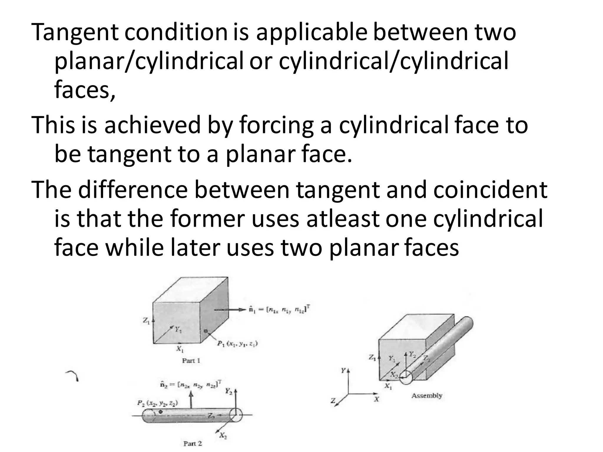
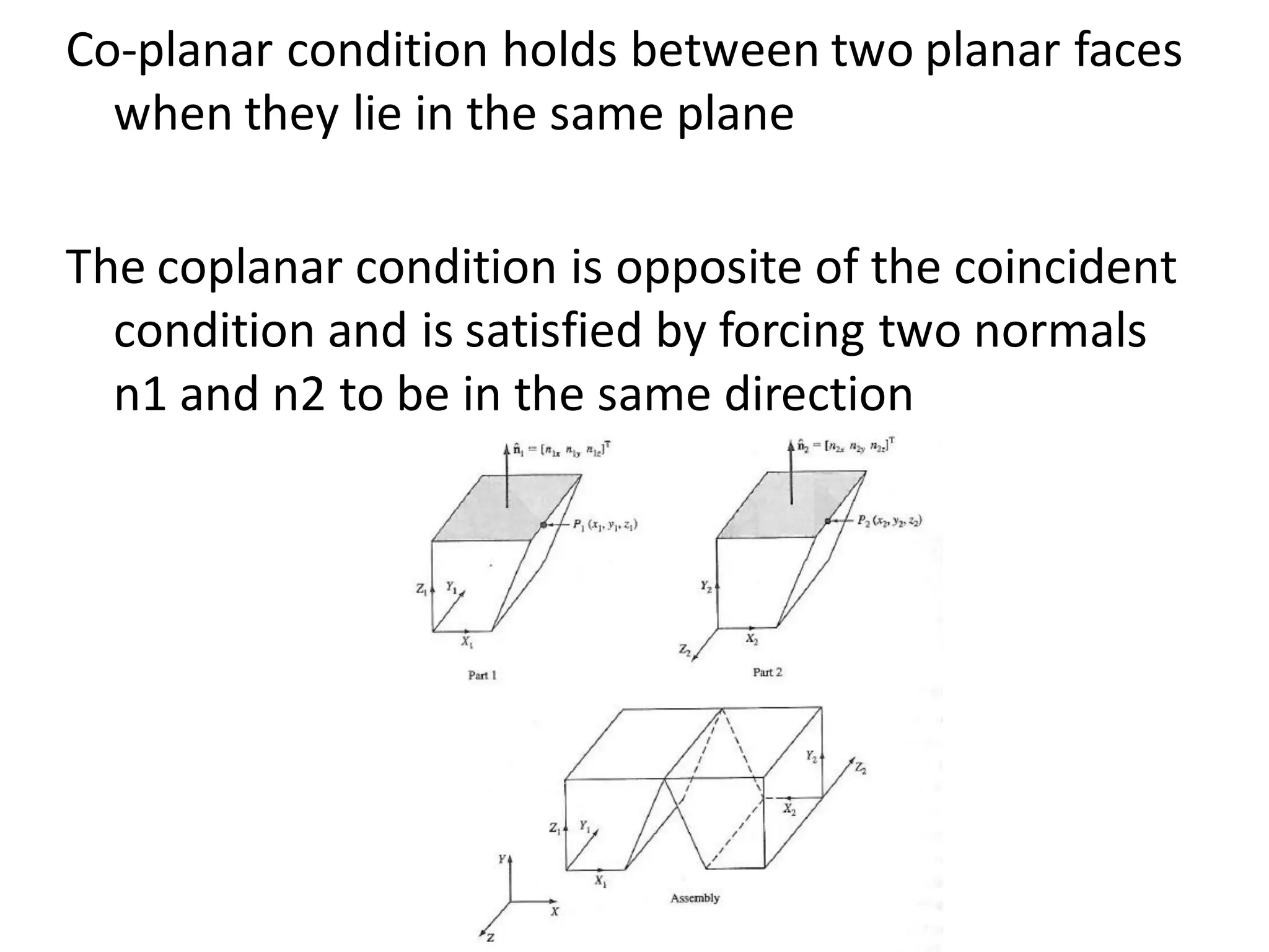
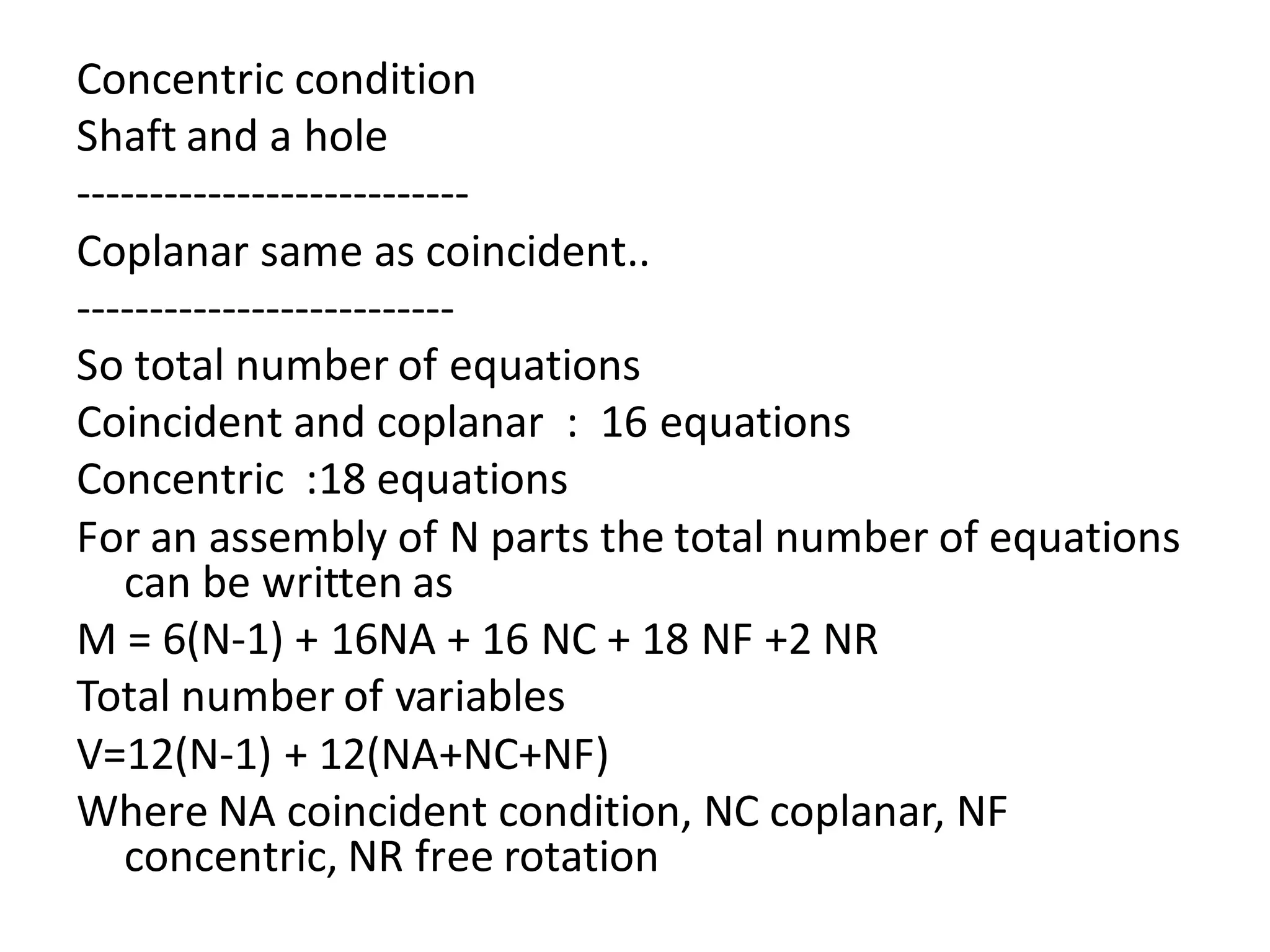
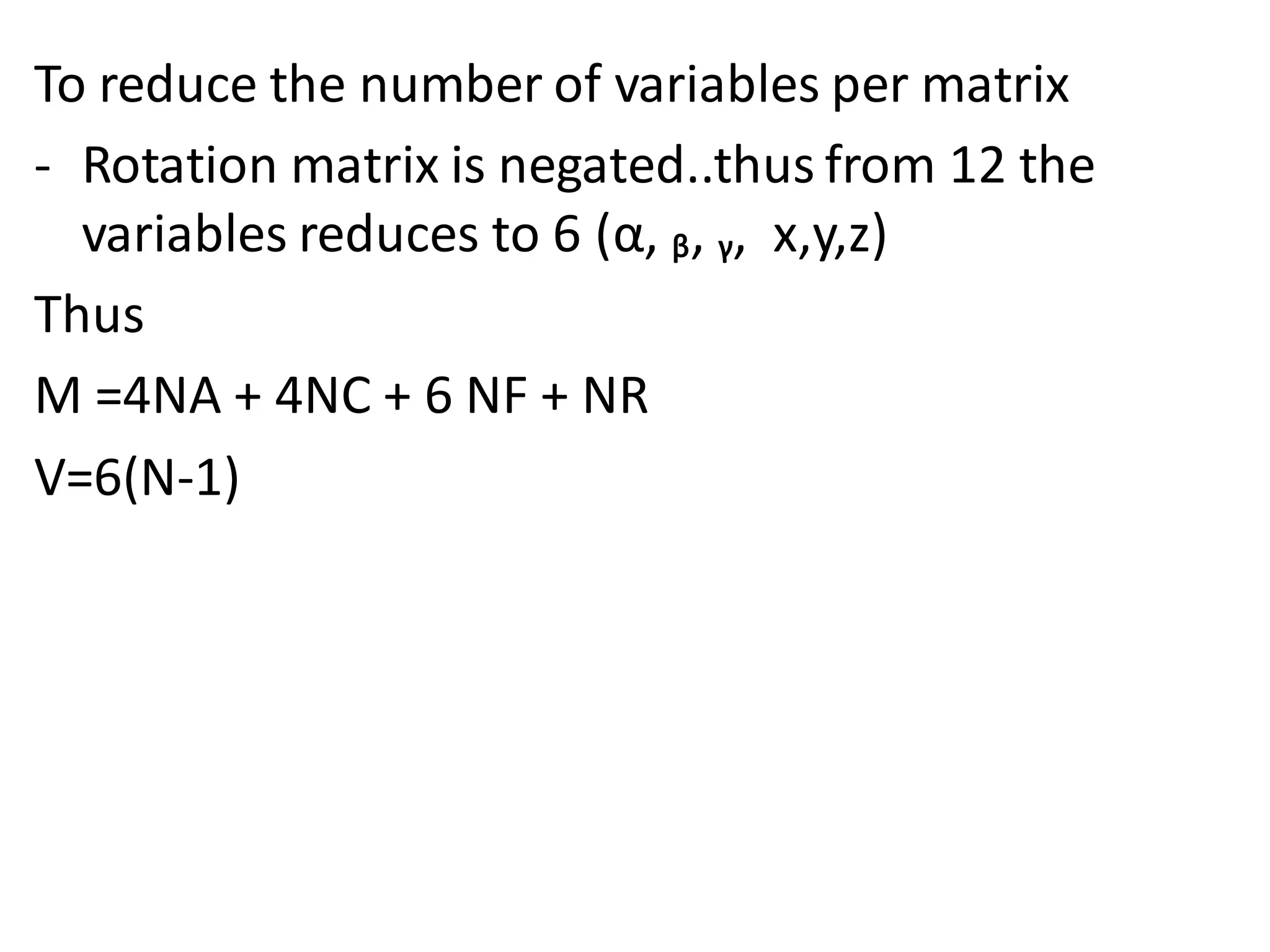
- Common mating conditions used to define spatial relationships between parts like coincident, concentric, coplanar, and their mathematical definitions.
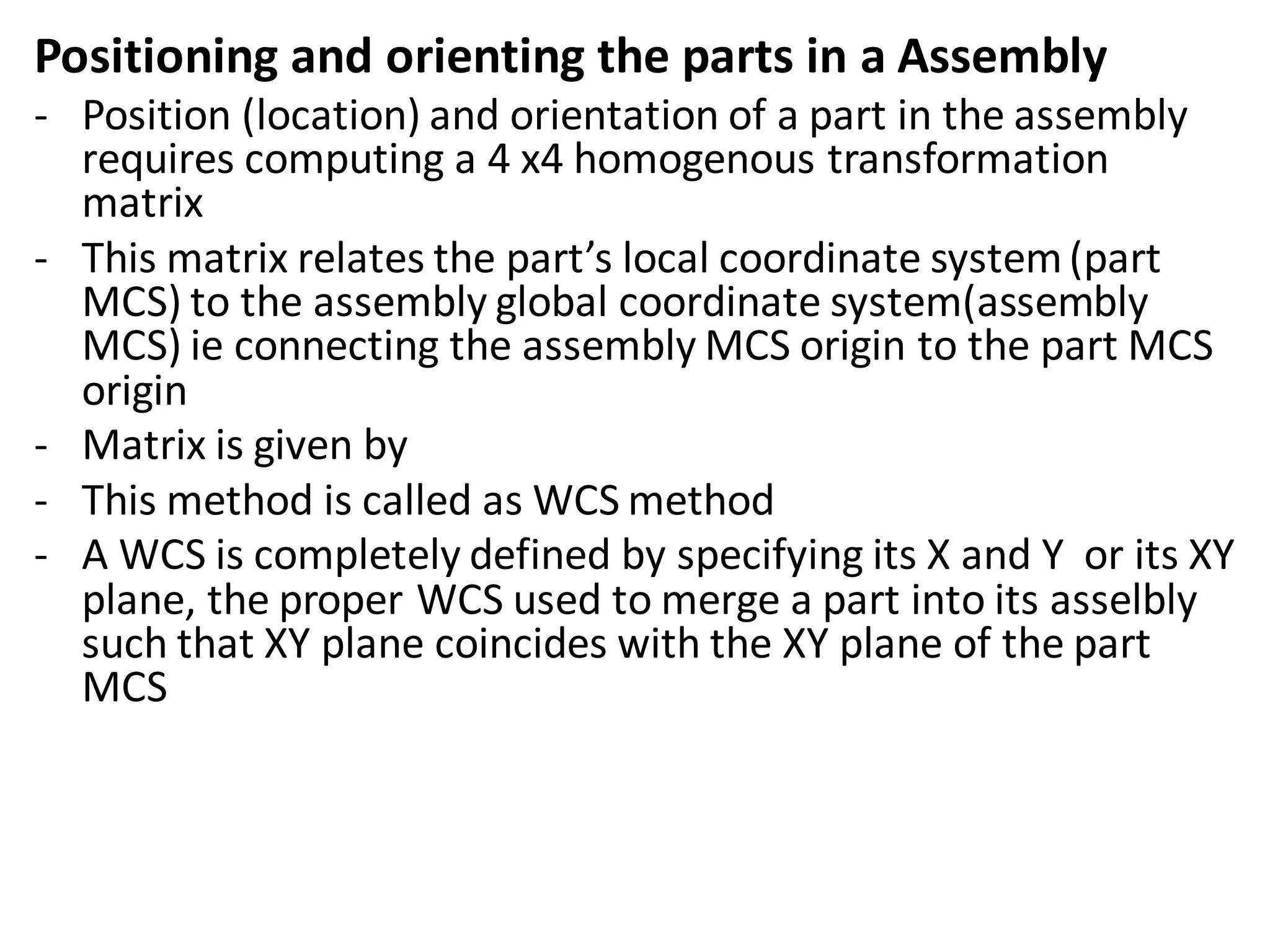
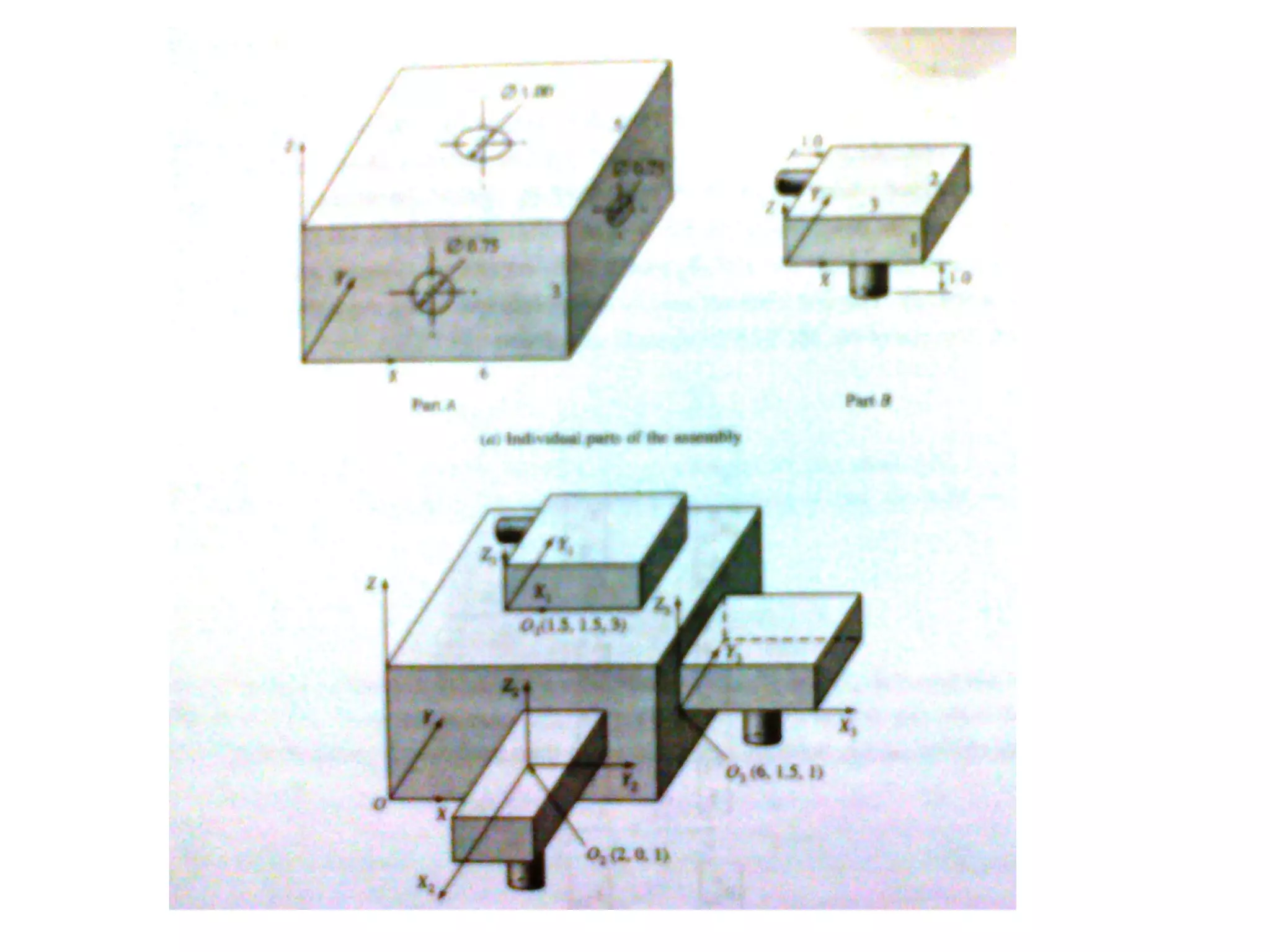
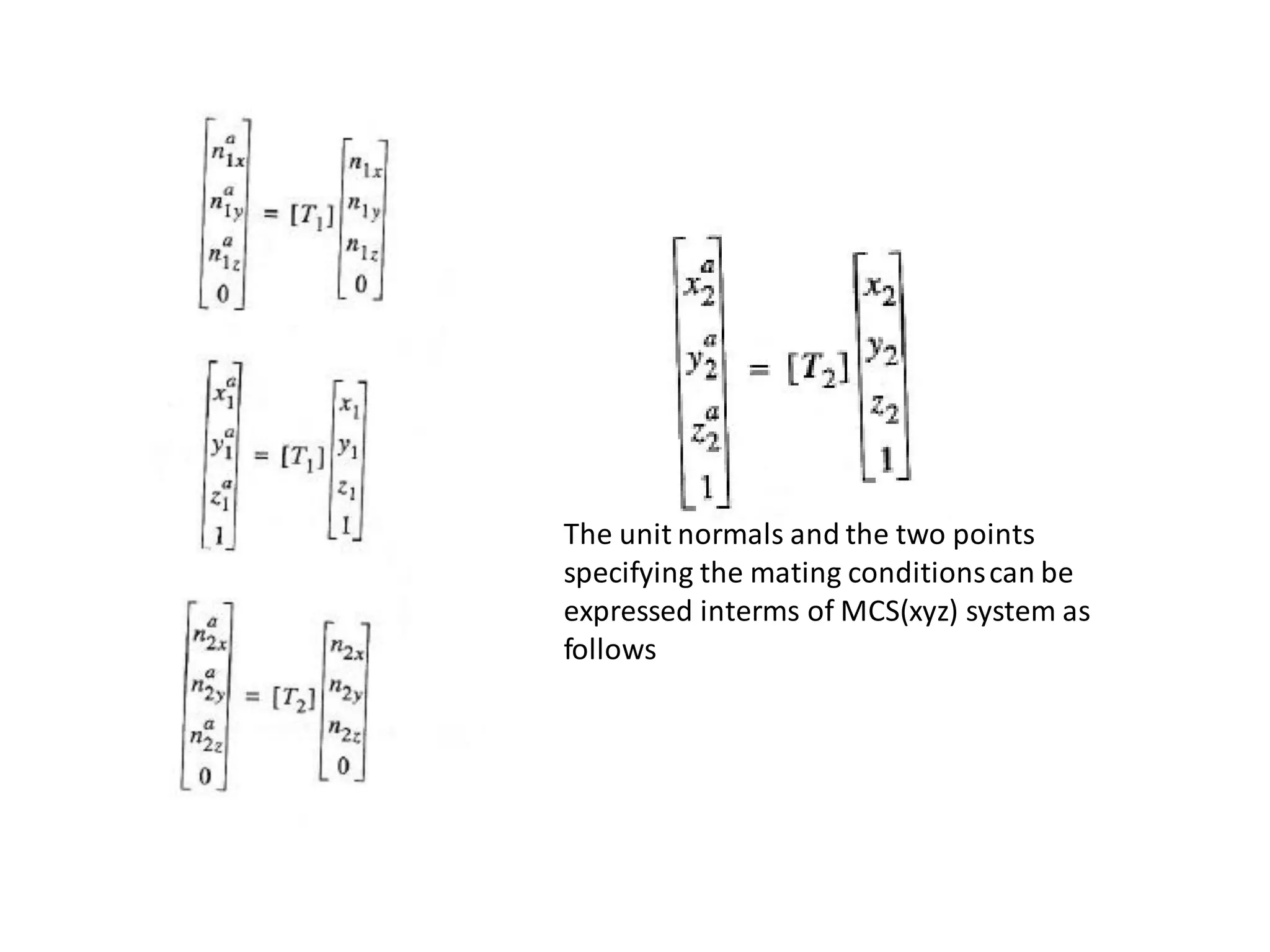
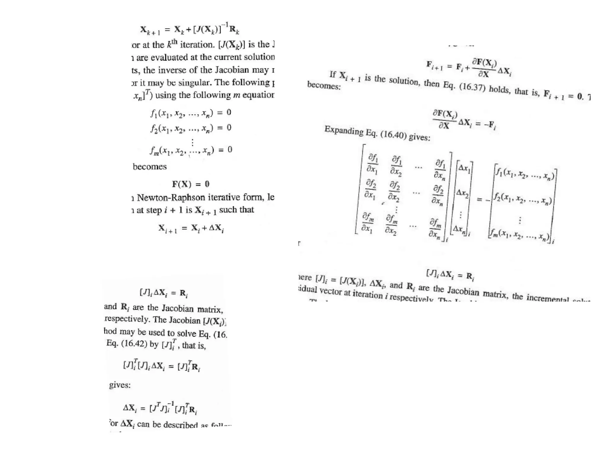
- Positioning and orienting parts in an assembly using transformation matrices and the world coordinate system method.
![Top down assembly approach
- Bottom up approach appeals to small assemblies consisting for
eg., hundred or maybe a thousand components
- Top down is suitable for large assemblies consisting of tens of
thousands of parts and sub assemblies
- Its an effective tool and a organised approach to manage the
design of large assemblies
- It allows a project leader to break up product specifications, assign work teams and
enforce downstream design changes at a high level
- It helps foster a systemsengineering approach to product design
- The assembly layout communicates design criteria to subsystem developers including
suppliers. The design control allows distributed design teams to work concurrently with a
common product framework
- It allows detail design to begin while the assembly layout is finalised
- This approach lends itself to conceptual design phase. Captures the design intent of a
product in the early design phases [doesn’t need to worry about detailed design]
- Allows designers to validate design concepts before implementing them, what if analysis
could be done](https://image.slidesharecdn.com/assemblymodelling-230309054901-06426287/75/assembly-modelling-pdf-22-2048.jpg)