Programming basics
•
0 likes•191 views

Basic programming for new programmers. Introduce the step-by-step in programming. Including C, C++, Python, Pascal.

Recommended
More Related Content
What's hot
What's hot (20)
Similar to Programming basics
Similar to Programming basics (20)
More from Rakotoarison Louis Frederick
Recently uploaded
Recently uploaded (20)
Programming basics
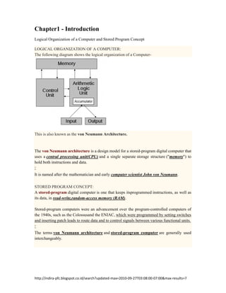
- 1. http://indira-pfc.blogspot.co.id/search?updated-max=2010-09-27T03:08:00-07:00&max-results=7 Chapter1 - Introduction Logical Organization of a Computer and Stored Program Concept LOGICAL ORGANIZATION OF A COMPUTER: The following diagram shows the logical organization of a Computer- This is also known as the von Neumann Architecture. The von Neumann architecture is a design model for a stored-program digital computer that uses a central processing unit(CPU) and a single separate storage structure ("memory") to hold both instructions and data. It is named after the mathematician and early computer scientist John von Neumann. STORED PROGRAM CONCEPT: A stored-program digital computer is one that keeps itsprogrammed instructions, as well as its data, in read-write,random-access memory (RAM). Stored-program computers were an advancement over the program-controlled computers of the 1940s, such as the Colossusand the ENIAC, which were programmed by setting switches and inserting patch leads to route data and to control signals between various functional units. The terms von Neumann architecture and stored-program computer are generally used interchangeably.
- 2. 1 Chapter2 - Programming Process Flowcharts WHAT IS A FLOWCHART? It is an organized combination of shapes, lines and text which graphically illustrate a process. A flowchart can be used as an alternative for an algorithm SYMBOLS USED IN FLOWCHARTS: The following table shows a listing of different symbols used in flowcharts along with their meaning and purpose – EXAMPLES: 1. Draw a flowchart to print the sum of two numbers.
- 3. 2 2. Draw a flowchart to print the average of any three numbers. 3. Draw a flowchart to print Area and Perimeter of a Square. 4. Draw a flowchart to print biggest of two numbers.
- 4. 3 5. Draw a flowchart to check whether a number is positive, negative or zero. 6. Draw a flowchart to print biggest of three numbers.
- 5. 4 7. Draw a flowchart to print a number ‘n’ 10 times. 8. Draw a flowchart to print all the odd numbers between 1 and n. 9. Draw a flowchart to print all the even numbers between 1 and n.
- 6. Life Cycle of a Software Project Software:- It is a collection of computer programs and related data that provide the instructions telling a computer what to do. Project:- It is a sequence of tasks planned from beginning to end bounded by time, resources and required results. So, a software project is a collection of programs and related data that are done in a planned manner with bounded time, resources and end results. A software development process is a structure imposed on the development of a software product. It is also called as a software life cycle or a software process. The following diagram shows the step-by-step procedure of Software Development - This diagram is known as Software Development Life Cycle (SDLC) Requirements phase: In this phase the required data about the project is collected and are categorized into different types of requirements. Design phase: At this stage the crude design of the whole project is made ready.
- 7. Implementation phase: This stage is concerned with the actual coding phase. The coding can be done in any languages. Verification phase: It is to verify that the implementation done in the previous stage meets all the requirements collected in the 1st phase. Maintenance phase: This is where the end product is put into use. User is using the product and if any changes are needed that are to be incorporated at this stage. All these phases may be repeated as many times as possible until the desired product is available.