Downloaded 104 times

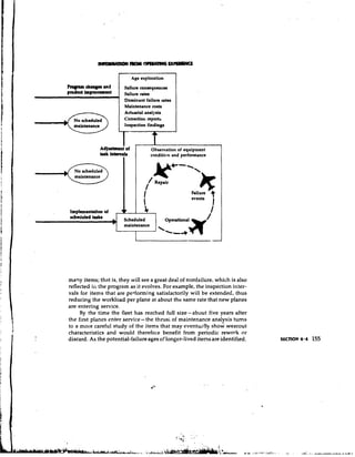
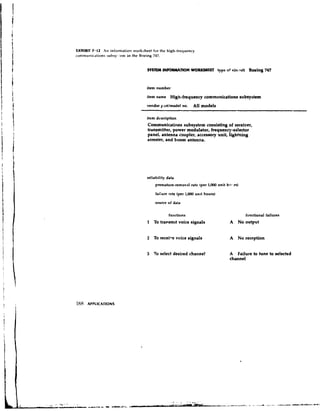
![nlent published under the title Handbook: Maintetranee Eval~rationand
lJro~ram Dtlvelopmenf,generally known as MSG-I.* MSG1 was used by
special teams of industry and FAA yersor~nel develop the initial pro-
to
grain issued by the FAA Maintenance Review Board for the Boeing 747.
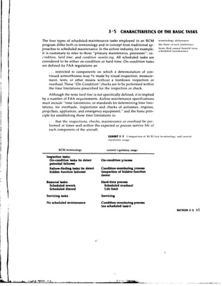
As described by the FAA, these t e a s s t
. . . sorted out the potentid maintenance tasks and then evaluated
them to determine which must be done for operating safel.y or
essential hidden function protection. The remaining potential tasks
were evaluated to determine whether they were economically use-
ful. These:procedures provide a systematic review of the aircraft
design so that, in the absence of real experience, the best [mainte-
nance] plocess can be utilized for each component and system.
The Boeing 747 maintenance program so developed was the first:attempt
to apply reliebility-centered mait;tenance concepts. This program has
been successful.
Subsequent improvements in the decision-diagram approach led
in 1970 tc a second document, MSG-2; AirlinclMarrrrfncturcr Mni~rtcnnricc
Program Plnnnitlg Documort, which was used to develop the scheduled-
maintenance programs for the Lockhred 1011 and the Douglas DC-lo.$
These programs have been successful. MSG-2 has also been applied to
tactical milit*.y aircraft such # i s the McDonnell F4J and the Lockheed
P-3, and a similar document , 1,epared in Europe was the basis of the
initial scheduled-maintenance programs for such recent aircraft as the
Airbus lndustric A-300 and the Concorde.
The objective of the techniques outlined by MSG-1 and MSG-:! was
tc develop a qcheduled-maintenance program that assured the maxi-
mum safety and reliability of whicn the equipment was capable and
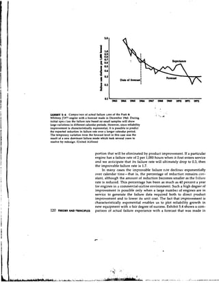
would meet this requirement at the lowest cost. As an example of the
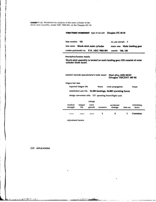
economic benefits achieved with this type of under traditional
maintenance policies the initial program for the Douglas DC-8 included
scheduled overhaul for 339 items, w h e r ~ a s initial progranl for the
the
DC-10, based on MSG-2, assigned only seven items to overhaul. One of
the items 110longer subject to an overhaul limit in the later progr.:! II was
the turbine engine. Elimination of this scheduled task qot only led to
major reduct,ons in labor and materials costs, but also reduced the spare-
engine inventory required to cover shop activities by more than 50
percent. Since engines for larger airplanes now cost upwards of $1
million each, this is a respectable saving.
'747 hlaintcnance Steering Group. 1111r1dl~ooA: Mr~itltc'tra~l~.r E~~slrrr~tiotr l1ro,.rr~ttrD r l ~ c - l ~ ~ l r -
r~tlrl
ttrc3tlt( M S G - I ) . Air Transport Association, July lo, 1UhA.
t f l , r l r m l Azliatiotl Adtttitlistrntiott Crrtificriticlrl l-'rt~ccdltres,May 19. 1972, par. 3036.
S A i r l i t ~ z l M n t ~ ~ c f r ~ ~ t ~ l t ~ tl ' ~ t nP~r lo~ ~ n t t P / ~ l l t l ~ ~ l) ~ C I O ~ I M ISI C -: 2 , Air Transport
Mt~it t ~r ~ t O ~ ~
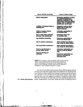
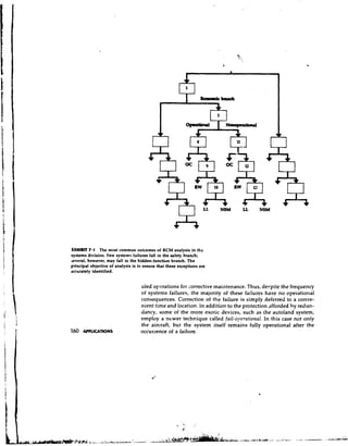
Association, H & M Subcommittee, Marcy 25, 1970. SECTION 1 . 1 5](https://image.slidesharecdn.com/nowlanandheapercmstudy-usdodfunded-130102173537-phpapp02/85/Nowlan-and-Heape-RCM-Study-US-DoD-funded-25-320.jpg)
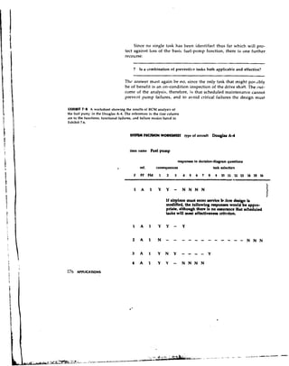
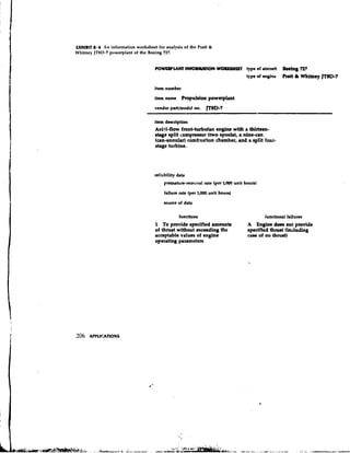
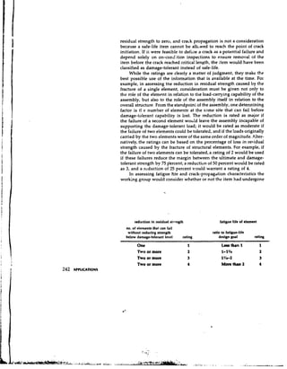
![modem design practices, however, very few items fa]! into this category,
either because an essential function is provided by more than one source
or because operating safety i s protected in some other way. Similarly,
hidden functions must be protected by schedultd maintenance, both
to ensure their availability and to prevent exposure to the risk of a
multiple failure.
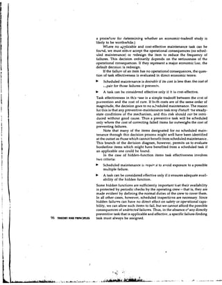
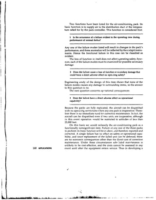
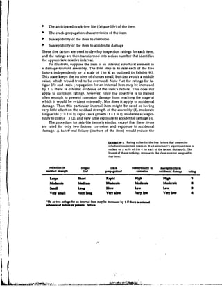
In all other cases the consequences of failure are economic, and the
value of preventive maintenance must be measured in economic terms.
In some cases these consequences are major, especially if a failure
affects the operational capability of the equipment. Whenever equip-
ment must be removed from service to correct a failure, the cost of fail-
ure includes that loss of service. Thus if the intended use of the eauip-
ment is of significant value, the delay or abandonment of that use
will constitute a significant loss-a fact that must be taken into account
in evaiuating the benefit of preventive maintenance. Other failures will
incur only the cost of correction or repair, and such failures may well be
tolerable, in the sense that it is less expensive to correct them as they
occur than to invest in the cost of preventing them.
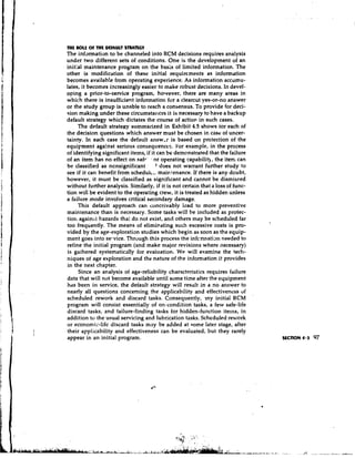
In short, the driving element in all maintenance decisions is not
the failure of a given item, but the consequences of that failure for the
equipment as a whole. Within this context it is possible to develop an
efficient scheduled-maintenance program, subject to the constraints of
satisfying safety requirements and meeting operational-performance
goals. However, the solution of such an optimization problem requires
certain specific information which is nearly always unavailable at the
time an initial program must be developed. Hence we also need a basic
strategy for decision making which provides for optimum maintenance
decisions, given the information available at the time. The process of
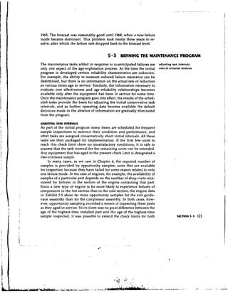
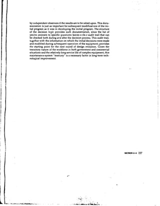
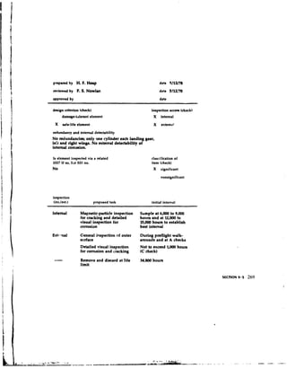
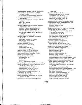
developing an initial RCM program therefore consists of the following
steps:
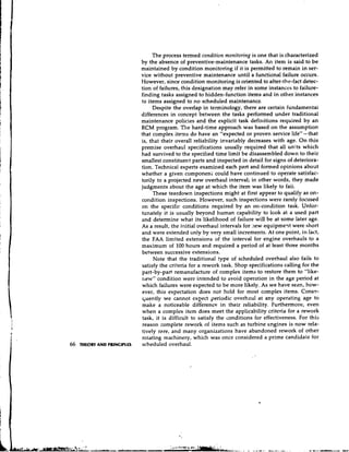
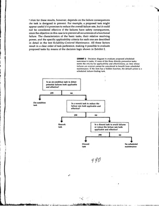
b Partitioning the equipment into object categories to identify those
items that require intensive study
b Identifying significant items, those whose failure would have safety
or major economic consequences for the equipment as a whule, and
all hidden functions, which require scheduled maintenance regard-
less of their significance
b Evaluating the maintenance requirements lor each significant item
and hidden function in terms of the failure consequences and select-
ing only those tasks which will satisfy these requirements
b Identifying items for u.hich no applicable and effective task can be
found and either recommending design changes if safety is involved
or assigning no scheduled-maintenance tasks to these items until
further information becomes available
I-,.](https://image.slidesharecdn.com/nowlanandheapercmstudy-usdodfunded-130102173537-phpapp02/85/Nowlan-and-Heape-RCM-Study-US-DoD-funded-27-320.jpg)

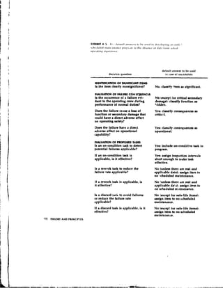
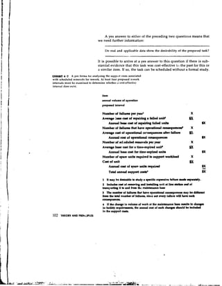
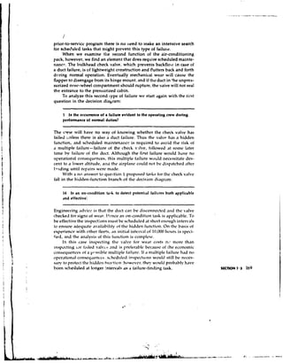
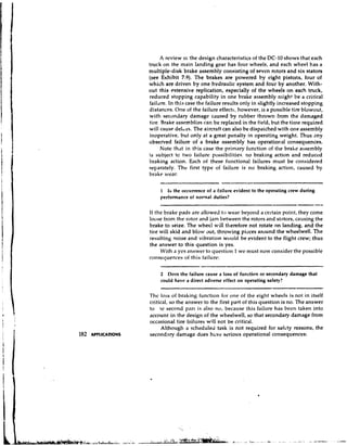
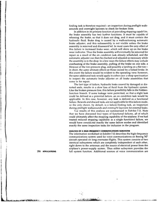
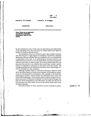
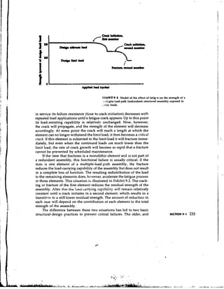
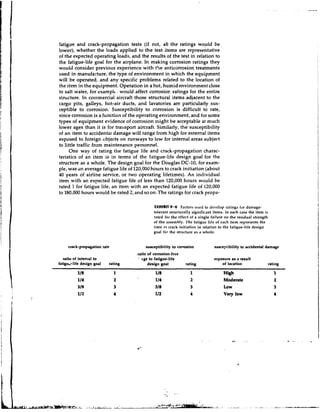
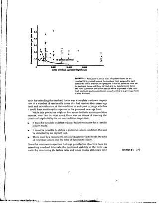
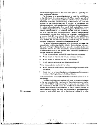
![fail (90 percent survive beyond this age):
.lo
[(age at P = 1) t (age at P = .90)] X -2
The next incremental area represents the contribution to the average life
of the next 10 percent of the units that fail:
[(age at P = .9Q + (age at P = .80)] X -
.10
2
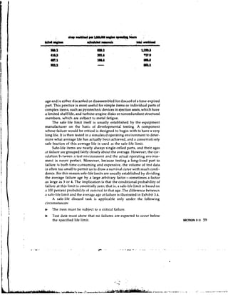
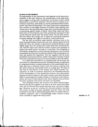
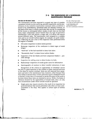
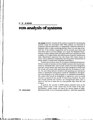
and so on. Completion of this computation for the entire area under the
curve would show that, with no age limit, the average life expected for
each engine in service would be 1,811 hours.
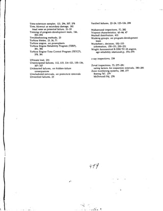
Note, however, that an age limit of 1,000 hours removes all the sur-
viving units from service at that age. In this case, therefore, the area
under the curve represents only the area up to that age limit. The proba-
bility of survival to 1,000 hours is .692, so the contribution of any sur-
viving unit to the average life is only 1,500 hours X ,692 = 692 hours.
This contribution, added to the incremental contributions above it for
the units that failed, yields an average realized life of 838 hours for faded
and unfailed engines. Any engines that would have survived to ages
higher thtn 1,000 hours, and thus have added to the average life, do not
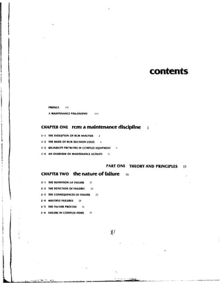
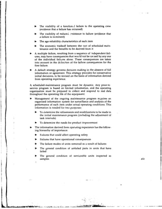
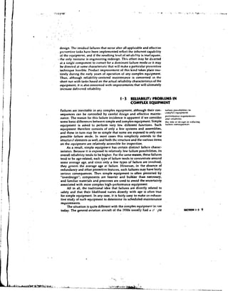
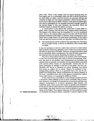
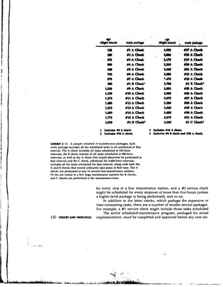
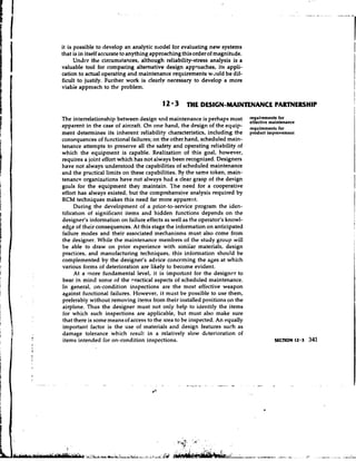
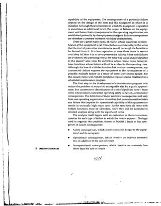
count. The average lives that would be realized with other age limits
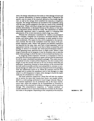
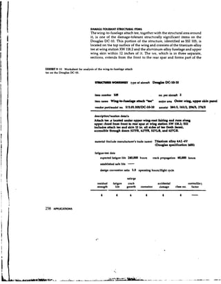
in this case are as follows:
age limit average realized life
1,000 hours 838 hours
2,000 hours 1,393 hours
3,000 hours 1,685 hours
No limit 1,811 hours
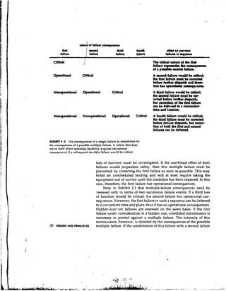
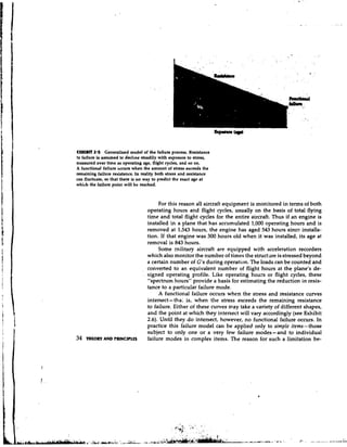
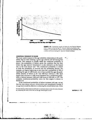
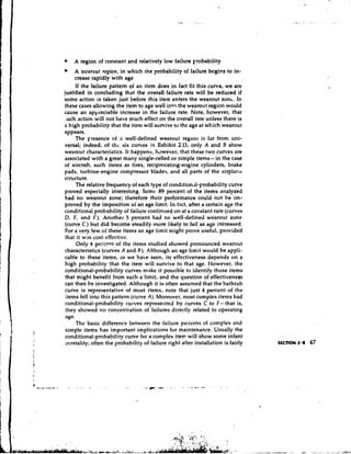
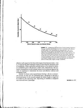
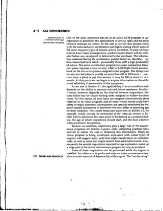
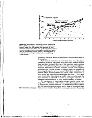
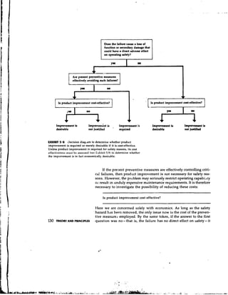
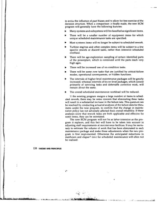
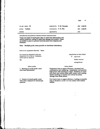
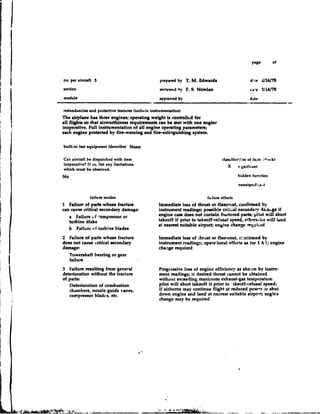
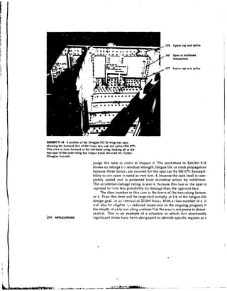
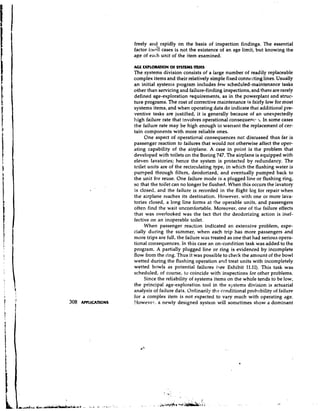
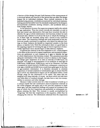
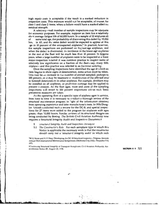
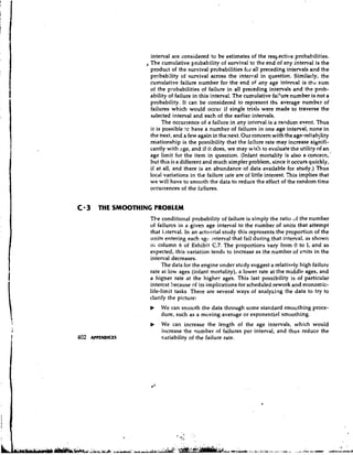
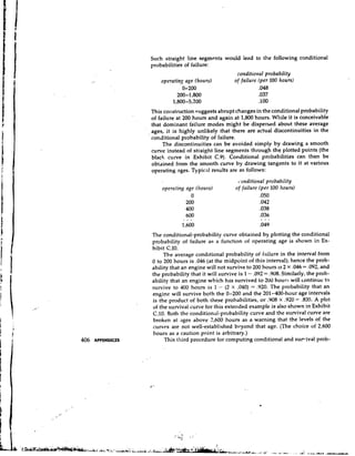
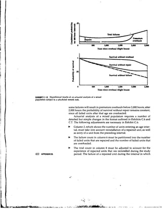
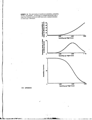
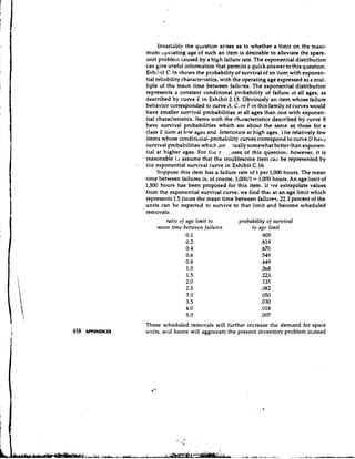
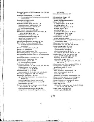
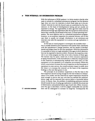
PROMBILITY DWSllY OF FNLUUE
The probability that an engine in Exhibit 2.9 will survive to 1,000 hours
is ,692, and the probability that it will survive to 1,200 hours is ,639. The
difference between these probabilities, .053, is the probability of a fail-
ure during this 200-hour interval. In other words, an averaae of 5.3 out
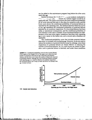
of every 100 engines that enter service can be expected to fail during..,
this partic~tlarinterval. Similarly, an average of 5.0 engines can be ex- '.
pected to fail during the interval from 1,200 to 1,400 hours. This measure ,
is called the probnbility density of failure. 7
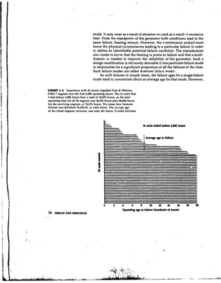
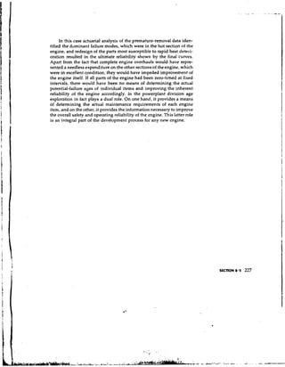
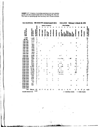
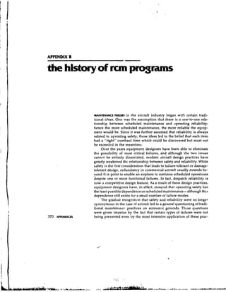
Exhibit 2.10 shows the probability densities for each 200-hour
age interval, plotted from the probabilities of survival at each age. A
decreasing percentage of the engines will fai! in each successive age
interval because a decreasing percentage of engines survives to enter
42 THEORY AND PRINCIPLS that interval.](https://image.slidesharecdn.com/nowlanandheapercmstudy-usdodfunded-130102173537-phpapp02/85/Nowlan-and-Heape-RCM-Study-US-DoD-funded-62-320.jpg)
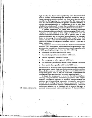
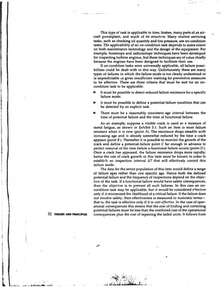
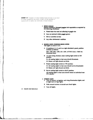
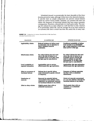
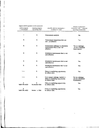
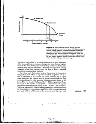
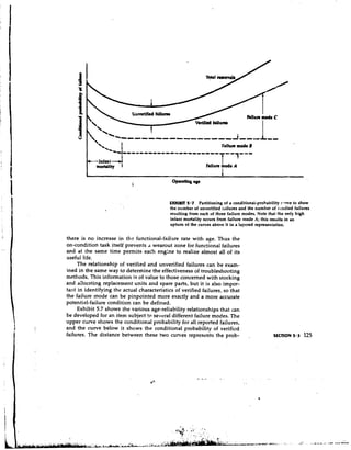
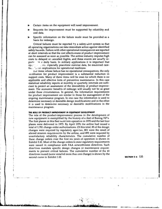
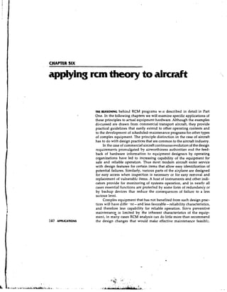
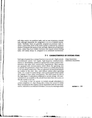
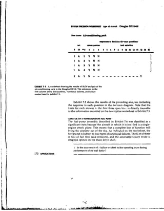
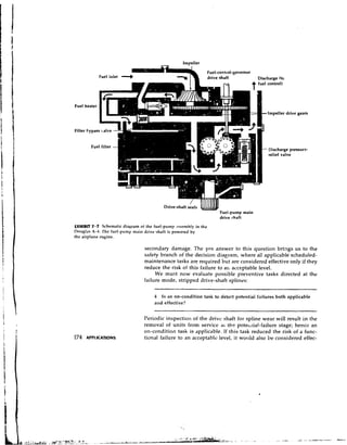
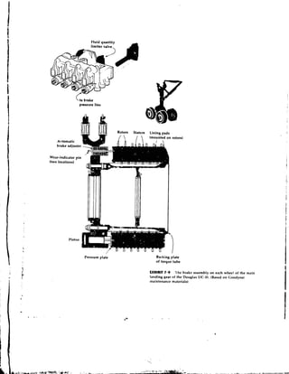
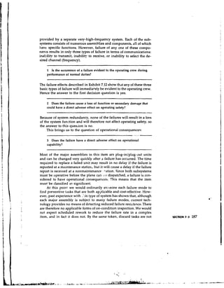
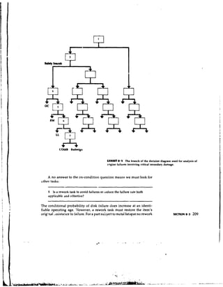
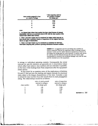
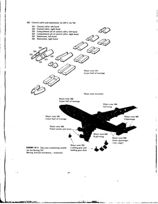
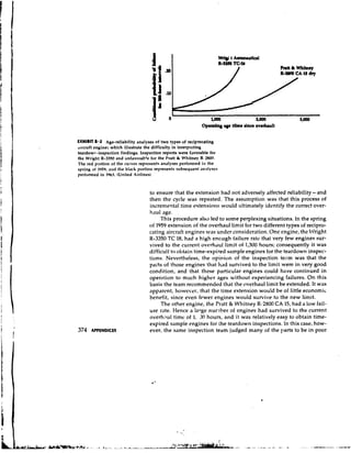
![(or other equipntent)
] Systems I
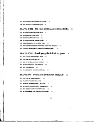
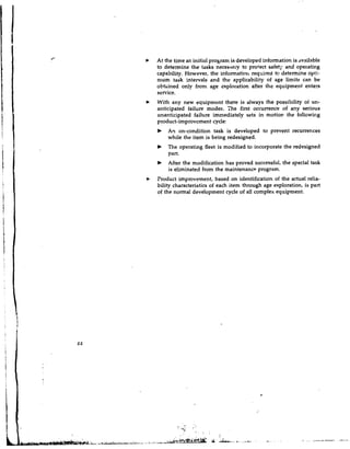
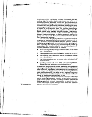
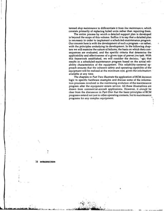
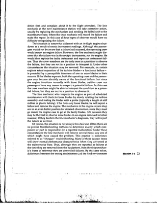
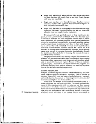
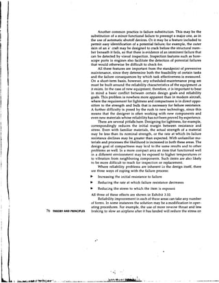
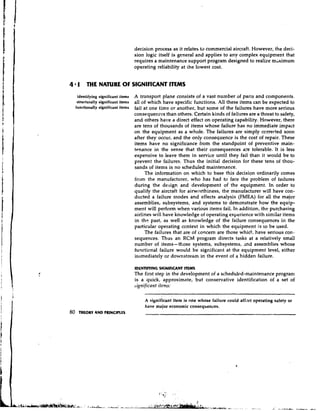
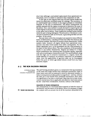
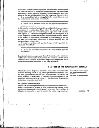
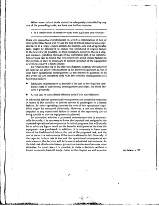
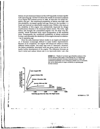
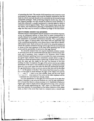
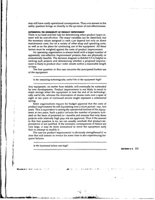
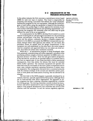
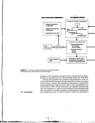
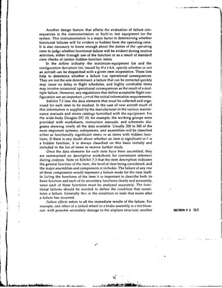
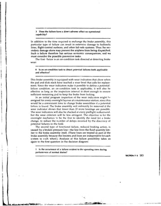
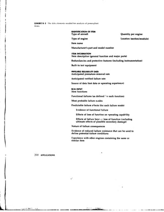
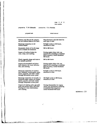
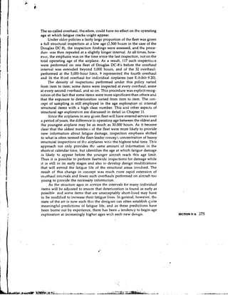
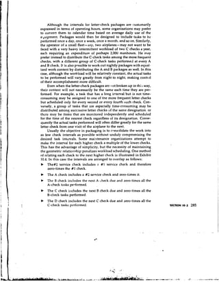
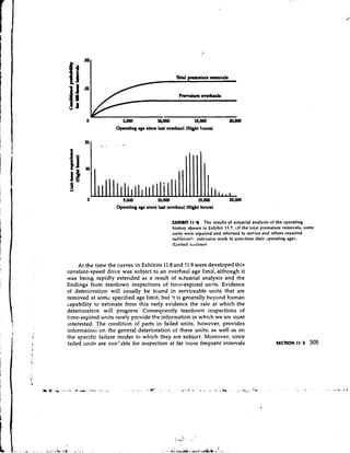
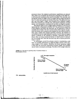
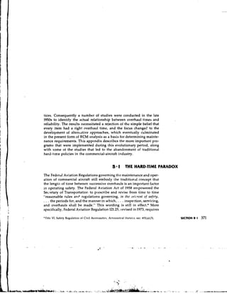
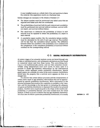
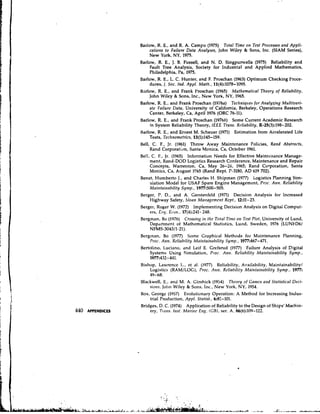
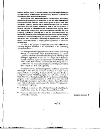
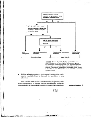
4.1 P~rtitioning aircraft for preliminary identitication of
an
significant iteins. The equipment is fin' partitioned to show all items
in descending order of comp:exity. rhose items wbose failure clcariy
tias nn sig~tific~nt con^-quencrs a! the equipment level are then p m ~ e d
from theqree, leavdg t!ie set oi ikms on which maintenance studies
mu . 5r cdhducted. E2ch significant itt?, will include as failure
r n ~ ~ rall ~ fai:ure possibilities it contains.
i e the
Tire obiectiv?, however, is to ftnd the tnos: convenient level of each
s;rstem or assembly to classify as significant. The level must be !ow
enougn to znsure that no important fai!ure possibilities are overlooked,
but high encjugh fdr the loss ol function to have an impact on the equip-
ment itself, since ihc consequences cf a functional failure are significant
only at the equipment level- that is, fzr the aircraft as a whole.
Once the optinlum level of item has been selected for study in each
x s e , we can prune the "trel?" back to a set of several I~undred poten-
tially significart items with the assurance that any failure possibilities
they include at lower levels will be taken into account as failure modes.
11s a n example, consider the engirie described in Section 3.1, in which
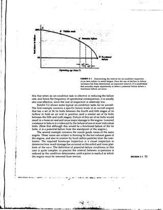
fai1u:e oi one or r;lore individual tie bolts in a set of 24 was defined as
a potcntial failure. Although this might be viewed as a functional fail-
ure of the tie bolt, thd failure of a single bolt does not affect engine
performance enough to be evident to the operating crew; consequently
the tie bolt is not a significant item. It does, htjwever, have a hidden
82 THkORY AND PRlNClPLfS function, and if enough tie bolts failed, the resulting multiple failure](https://image.slidesharecdn.com/nowlanandheapercmstudy-usdodfunded-130102173537-phpapp02/85/Nowlan-and-Heape-RCM-Study-US-DoD-funded-102-320.jpg)


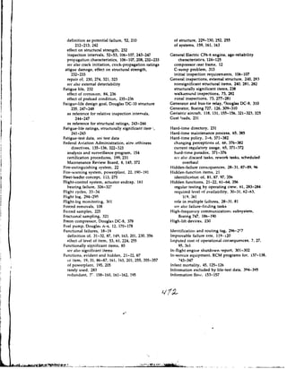
![airplane is desipned. For example, one of the load requirements for
structures in the commercial-transport category is defined as follows:*
25.341 Gust Loads
a The airplane is assumed to be subjected to symmetrical vertical.
gusts in level flight. The resulting limit load factors must cor-
respond to the conditions determined as follows:
I Positive (up) and negative (down) raugh air gusts of 66 ips
at V H [the design speed for maximum gust intensity] must
be considered at altitudes between sea level and 20,000 feet.
The gust velocity may be reduced linearly from 66 fps at
20,000 feet to 38 fps at 50,000 feet.
2 Positive and negative gusts of 50 fps at V(.[the design cruis-
ing speed] must be considered at altitudes between sea level
.r.d 20,000 feet. The gust velocity may be reduced Ilnearly
irolil 30 fps at 20,000 feet to 25 fps at 50,000 feet.
3 Positive and negative gusts of 25 fps at V,, [the design dive
speed] must be considered at altitudes between sea level
and 20.000 feet. The gust vdocity may- be reduced linearly
fro111 25 fps at 20,000 feet to 12.5 fps at 50,000 fret.
During the development and certification of any new aircraft the
manufacturer conducts numerous tests to confirm that each structural
assembly can withstand the specified design loads without damage or
- permaxlent deformation. Design loads with this objective are called limit
loads. There are also requirements that the structure be able to with-
stand at least 150 percent of the limit load without collapsing (experi-
encing a functional failure). When design loads are factored upward
in this way they are called ultimate loads. The present airworthiness
requirements for design strength have been effective in protecting
against functional failures as long as the specified load-carrying capa-
bilities of the structure are preserved.
After the airplane enters service the operating organization is
responsible both for preserving the design strength of the structure and
also for ensurinb that the operating gross weight of the airplane does
not exceed the maximum weight at which the structure can satisfy the
various l o ~ drequirrments.
THE FATIGUE PROCUS
All the loads to which an aircraft structure is subjected are repeated
rnany times throughout the col;rse of its operating life. Although ar.y
single load application may be only a fraction of the load-carrying
capability of the element, the stress impos.ld by each one reduces the
*F~.drrnl Avintiot~ R~-&rtlatiotrs,Airworthiness Standards: Transport Categoty Airpl'lnes,
sec. 25.341, effcclivc Februar).. 1, 19h5.](https://image.slidesharecdn.com/nowlanandheapercmstudy-usdodfunded-130102173537-phpapp02/85/Nowlan-and-Heape-RCM-Study-US-DoD-funded-251-320.jpg)


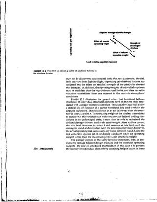
![and the size of the maintenance crew, it may take the airplane out of
senrice fot a week to several months.
The first of these complete inspections is a very important part of
the age-exploration program, since it incl~rdesmany inspections that
are being performed for the first time. The first airplane that ages to the
initial interval becomes the inspection sample; the findings for each
item are carefully evaluated, tasks and intervals for individual items
are adjusted as necessary, and the conservative initial inkerval for the
D-check package is extended. Consequently, although external inspec-
tions fire performed on every airplane, most internal items will be
inspected at the initial interval only on the first one or first few air-
planes to reach this age limit. They will, however, be inspected at suc-
cessive]!~ higher ages as the equipment ages in service, often 0x1 a fleet-
leader sampling basis.
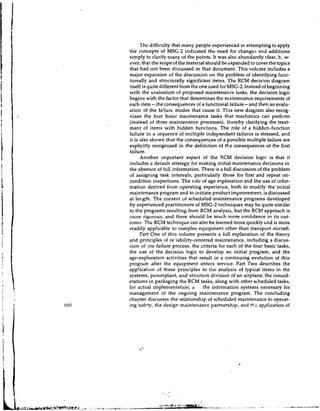
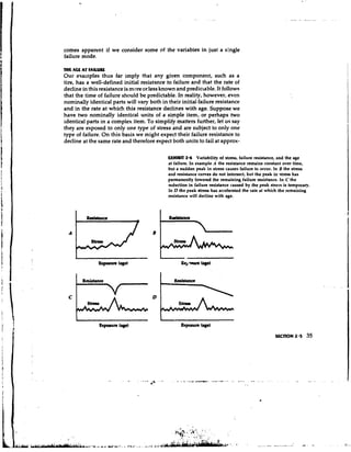
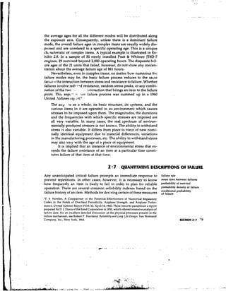
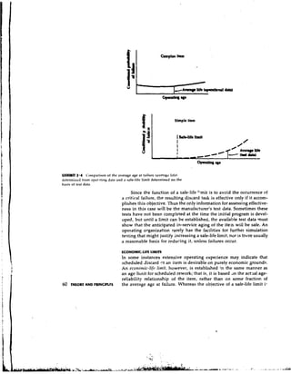
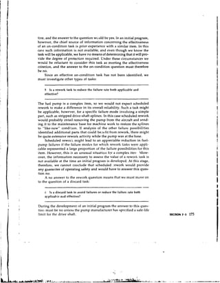
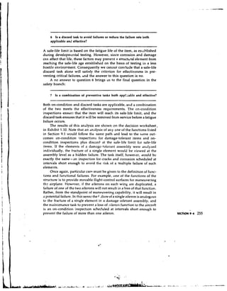
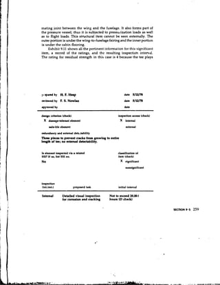
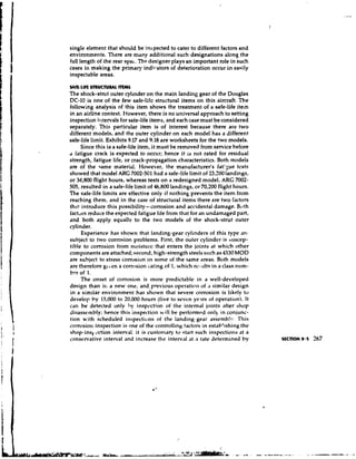
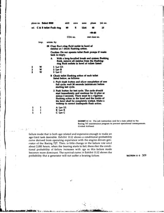
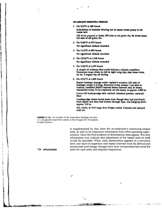
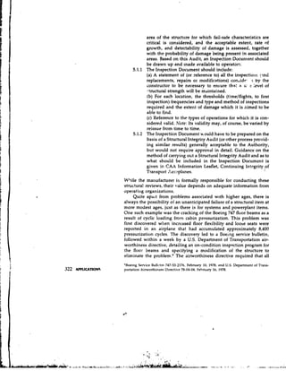
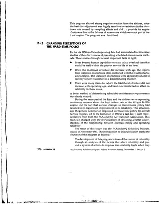
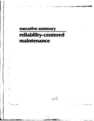
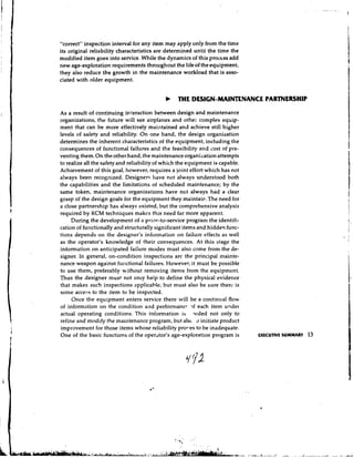
9 - 4 RCM ANP.3SIS O STRUCTURAL ITEMS
F
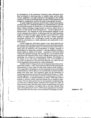
analysis of damage-tolerant As we saw in Chapters 7 and 8, RCM analysis of systems and power-
rlrmcnts
plant items may fall in any branch of the decision diagram. In contrast,
analvsis oi safe-litr rlr~nents
all structurally significant items fall in the safety branct and the eval-
uation of proposed tasks can have only one of two possible outconies
(see Exhibit 9.9). This is true no matter which of the structural functions
we consider. As an example, one function of the aircraft structure is to '
permit lifting forces to balance the weight of the airplane. Although
most uf the lift is provided by the wing, its center of lift does not neces-
sarily coincide with the airplane's center of gravity, and the horizontal
stabilizer must provide a balancing load that brings the vertical folces
into equilibrium. The portions of the structure ~ssociatedwith this
function, therefore, are the wing, the fuselage, and the horizontal tail.
The first question is whether a loss c.f the balancing function will
be evident:
1 Is the occurrence of a failure evident to the operating crew during
performance of nonrlal duties?
The answer is yes, of course, since a loss of this function as the result
of a structural failure would be a!l tot>evident, not only to the crew, but
to any other occupants of the airplane as well.
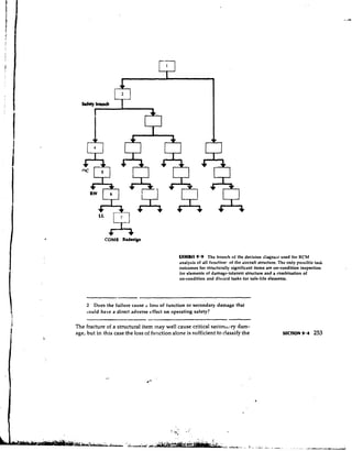
Next we would ordinarily examine the various failure modes that
could cause such a failure. In the case of structural items, however,
the failure modes all involve the fracture of a load-carrying metnbvr.
252 AHLICA~~N~ Thus the following question relates to any of the failure possibilities:](https://image.slidesharecdn.com/nowlanandheapercmstudy-usdodfunded-130102173537-phpapp02/85/Nowlan-and-Heape-RCM-Study-US-DoD-funded-272-320.jpg)


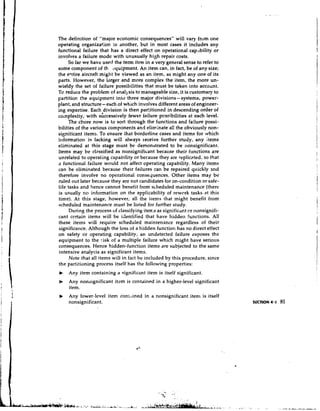
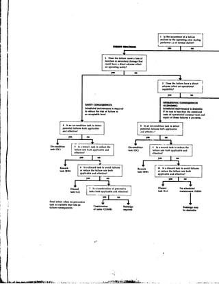
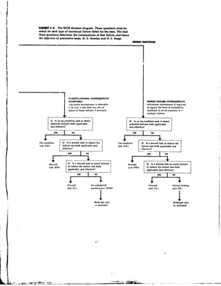
The document outlines the principles of Reliability-Centered Maintenance (RCM) and its applications in developing efficient maintenance programs for complex equipment, specifically within military contexts. It details the rationale for maintenance tasks, the systematic decision-making processes involved, and the importance of a collaborative approach between design and maintenance teams. Additionally, it discusses various maintenance tasks, evaluation criteria, and the necessary management information systems to sustain ongoing programs.