SlideShare a Scribd company logo
1 of 9
Download to read offline
IJRET: International Journal of Research in Engineering and Technology eISSN: 2319-1163 | pISSN: 2321-7308
__________________________________________________________________________________________
IC-RICE Conference Issue | Nov-2013, Available @ http://www.ijret.org 50
EFFECT OF SKEW ANGLE ON STATIC BEHAVIOUR OF REINFORCED
CONCRETE SLAB BRIDGE DECKS
Sindhu B.V1
, Ashwin K.N2
, Dattatreya J.K.3
, S.V Dinesh4
1
Post Graduate Student, 2
Assistant Professor, 3
Research Professor, 4
Professor and Head, Department of Civil
Engineering, Siddaganga Institute of Technology, Tumkur
sindhubvr@gmail.coml, meetashwinkn@yahoo.com, jk.dattatreya@gmail.com, dineshsv2004@yahoo.com
Abstract
The effect of a skew angle on single-span reinforced concrete bridges is analyzed using the finite-element method and the results are
presented in this paper. Investigations are carried out on RC slab bridge decks with and without edge beams to study the influence of
aspect ratio, skew angle and type of load. The finite-element analysis results for skewed bridges are compared to the reference
straight bridges for dead load, IRC Class A loading and IRC 70R loading for with and without edge beam. A total of 90 bridge models
are analyzed. The variation of maximum deflection, maximum longitudinal sagging bending moment, maximum torsional moment, and
maximum support reaction with skew angle is studied for all 90 bridge deck models. The FEA results of Dead load and Live load
bending moments and deflections decreases with increase in skew angle, where as maximum support reactions increases with increase
in skew angle and the maximum torsional moment increases with skew angle up to 45 degrees and there after decreases. The benefit
of providing edge beam is reflected in significant decrease in deflection, longitudinal bending moment and torsional moment.
Keywords: Bridges, skew angle; Concrete slabs; Finite element method; span length; dead load; IRC Class A loading
and IRC Class 70R loading.
----------------------------------------------------------------------***-----------------------------------------------------------------------
1. INTRODUCTION
Skewed bridges are often encountered in highway design
when the geometry cannot accommodate straight bridges. The
skew angle can be defined as the angle between the normal to
the centreline of the bridge and the centreline of the abutment
or pier cap, as described in Fig. 2. Skew bridges have become
a necessity due to site considerations such as alignment
constraints, land acquisition problems, etc. The presence
of skew in a bridge makes the analysis and design of bridge
decks intricate. For the Slab bridge decks with small skew
angle, it is considered safe to analyze the bridge as a right
bridge with a span equal to the skew span.
In non skewed bridges, the load path is straight toward the
support (Fig 1a). In skewed bridges, the load tends to take a
shortest path to the nearest support i.e. to the obtuse corners of
the bridge here the maximum deflection occurs at obtuse
angled corner (Fig 1b).
Khaleel et al., (1990) presented a method for determining
moments in continuous normal and skew slab-and-girder
bridges due to live loads. Menassa et al. (2007) compared the
effect o skew angle with reference to straight bridge and
reported that the bridges with skew angle less than 20 degree
can be designed as non skew as the moments are almost same
for both. Vikash Khatri et al. (2012) compared grillage
method and finite element method of analysis and
recommended the use of FEM because of closes agreement
with the exact solution. Patrick Theoret et al., (2012) studied
the bending moments and shear forces, required to design
skewed concrete slab bridges.
(a) (b)
Fig1. Direction of moment flow in straight and skewed bridge decks
IJRET: International Journal of Research in Engineering and Technology eISSN: 2319-1163 | pISSN: 2321-7308
__________________________________________________________________________________________
IC-RICE Conference Issue | Nov-2013, Available @ http://www.ijret.org 51
Fig2: Skew Bridge
2. PARAMETRIC STUDY
A simply supported, single span, two lane RC slab bridge deck
is considered. The span is varied from 5, 7.5 and 9.5m (aspect
ratio 1) and skew angle is varied from 0° to 60° at 15° interval
is considered with the depth of the slab 750mm for all spans.
Edge beam of depth 1.5m and width of 0.3m is provided. The
bridge deck is analyzed for Dead load as well as two classes of
live load i.e. IRC Class A and IRC Class 70R. Comparison of
critical structural response parameter of above cases is
presented in the following for slabs with and without edge
beam. A total of 90 slab deck models have been analyzed
Table 1: Geometric parameters slab bridge decks
No Span(m) Width(m) Aspect ratio
(span/width)
1 5 9.5 0.526
2 7.5 9.5 0.789
3 9.5 9.5 1
3. LOAD ON BRIDGE DECK MODELS
The vehicular live load consist of a set wheel loads and are
treated as concentrated loads acting at centres of contact areas,
two classes of load i.e. IRC Class A and IRC 70R are
considered for analysis. The peak values of critical structural
response parameter such as deflection, longitudinal sagging
bending moment, torsional moment and support reaction are
analyzed. Different positions of each type of loading systems
are considered from table 2 of IRC 6:2000.
4. FINITE ELEMENT MODELING
The analysis is carried out using finite element method. The
concrete slabs are modelled using four noded plate elements
and edge beams using two noded beam elements. Simple
support condition is provided.
ELASTIC MODULUS 25000 Mpa
POISSON'S RATIO 0.2
DENSITY OF CONCRETE 25kN/m2
5. RESULTS AND DISCUSSION
The FEA results are obtained and presented in terms of critical
structural response parameter such a deflection, longitudinal
sagging bending moment, torsional moment, and support
reaction in the bridge deck models due to the applied wheel
load. The variations of the critical structural response
parameter due to changes in skew angle are presented in the
following.
5.1 Deflection
• It is observed that the maximum deflection for
skewed slab deck for all types of load compared to
that of straight deck slab decreases with the
increase in skew angle for all aspect ratios as
IJRET: International Journal of Research in Engineering and Technology
__________________________________________________________________________________________
IC-RICE Conference Issue | Nov-2013, Available @
shown in figure 3. This is because the
force flow between the support lines
strip area connecting the obtuse angled corners, a
skew increases the length of strip area decreases
Hence the bending moment and
registers significant reduction.
• When the deflection for different skew angle and
aspect ratios are normalised with respect to the
deflection corresponding to zero skew
particular aspect ratio. The different
in fig 3(a) nearly merge into a single curve as
shown in fig 6(a).
a) Dead Load (Without Edge Beam
c) IRC Class A Load (Without Edge Beam
0
0.2
0.4
0.6
0.8
1
1.2
0 20 40
DEFLECTION(mm)
SKEW ANGLE (DEGREES)
IJRET: International Journal of Research in Engineering and Technology eISSN: 2319
__________________________________________________________________________________________
2013, Available @ http://www.ijret.org
. This is because the maximum
lines is through the
strip area connecting the obtuse angled corners, as
skew increases the length of strip area decreases.
and deflection also
When the deflection for different skew angle and
aspect ratios are normalised with respect to the
deflection corresponding to zero skew of that
particular aspect ratio. The different curves as seen
3(a) nearly merge into a single curve as
• The normalized deflection i.e.
decks without edge beam
reduces from unit value to 0.26 f
for IRC Class A load,
Class 70R load
• The deflection of deck slab decreases
provision of edge
decks without edge
reduction in deflection due to the provision of
edge beam in the slab bridge deck.
Without Edge Beam) b) Dead Load (With Edge Beam
Without Edge Beam) d) IRC Class A Load (With Edge Beam
60
SKEW ANGLE (DEGREES)
0.526
0.789
1
0
0.2
0.4
0.6
0.8
0 20 40
DEFLECTION(mm)
SKEW ANGLE (DEGREES)
eISSN: 2319-1163 | pISSN: 2321-7308
__________________________________________________________________________________________
52
The normalized deflection i.e. Dα/D0 for slab
decks without edge beams for all aspect ratios
reduces from unit value to 0.26 for dead load and
IRC Class A load, unit value to 0.64 for IRC
70R load.
he deflection of deck slab decreases with the
provision of edge beam compared to the slab
without edge beam. There is nearly 10%
reduction in deflection due to the provision of
edge beam in the slab bridge deck.
With Edge Beam)
With Edge Beam)
40 60
SKEW ANGLE (DEGREES)
0.526
0.789
1
IJRET: International Journal of Research in Engineering and Technology
__________________________________________________________________________________________
IC-RICE Conference Issue | Nov-2013, Available @
e) IRC Class70R Load (Without Edge Beam) f) IRC Class 70R Load (With Edge Beam)
Fig 3 Variation of Deflection Due To Dead Load
5.2 Longitudinal Bending Moment
• The trend in longitudinal bending moment is similar
to deflection. It is observed that the maximum dead
load longitudinal bending moment and
longitudinal bending moment for skewed
compared to that of straight deck slab decreases with
the increase in skew angle for all aspect ratios
shown in fig 4. This is because the force flow
between the support lines is through the strip area
connecting the obtuse angled corners, as skew
increases the length of strip area decreases therefore
the moment decreases.
• When the longitudinal bending moment for differen
skew angle and aspect ratios are normalised with
a) Dead Load (Without Edge Beam) b) Dead Load (With Edge Beam)
0
0.5
1
1.5
0 20 40
DEFLECTION(mm)
SKEW ANGLE (DEGREES)
-250
-200
-150
-100
-50
0
0 20 40
LongitudinalSagging
BendingMoment(kNm)
Skew Angle (Degrees)
IJRET: International Journal of Research in Engineering and Technology eISSN: 2319
__________________________________________________________________________________________
2013, Available @ http://www.ijret.org
e) IRC Class70R Load (Without Edge Beam) f) IRC Class 70R Load (With Edge Beam)
Deflection Due To Dead Load and Live Load on Deck Slab without
The trend in longitudinal bending moment is similar
It is observed that the maximum dead
longitudinal bending moment and wheel load
for skewed deck slabs
compared to that of straight deck slab decreases with
for all aspect ratios as
This is because the force flow
between the support lines is through the strip area
connecting the obtuse angled corners, as skew
increases the length of strip area decreases therefore
When the longitudinal bending moment for different
skew angle and aspect ratios are normalised with
respect to the longitudinal bending moment
corresponding to zero skew of that particular aspect
ratio. The different curves as seen in fig 4(a) nearly
merge into a single curve as shown in fig 6(b).
• The normalized longitudinal bending moment i.e.
Mα/M0 varies from unity to
without edge beam
IRC Class A load and unity to 0.79 for IRC Class
70R load for all aspect ratios.
• The longitudinal bending moment
provision of edge beam for both dead load and wheel
load compared to without edge beam. There
10% reduction in
to the provision of edge beam in the slab bridge deck.
a) Dead Load (Without Edge Beam) b) Dead Load (With Edge Beam)
60
SKEW ANGLE (DEGREES)
0.526
0.789
1
0
0.2
0.4
0.6
0.8
1
0 20 40
DEFLECTION(mm)
SKEW ANGLE (DEGREES)
40 60
Skew Angle (Degrees)
0.526
0.789
1
-160
-140
-120
-100
-80
-60
-40
-20
0
0 20
LongitudinalSagging
BendingMoment(kNm)
Skew Angle (Degrees)
eISSN: 2319-1163 | pISSN: 2321-7308
__________________________________________________________________________________________
53
e) IRC Class70R Load (Without Edge Beam) f) IRC Class 70R Load (With Edge Beam)
without and With Edge Beams
respect to the longitudinal bending moment
corresponding to zero skew of that particular aspect
ratio. The different curves as seen in fig 4(a) nearly
merge into a single curve as shown in fig 6(b).
rmalized longitudinal bending moment i.e.
varies from unity to 0.33 for deck slabs
out edge beam for dead load, unity to 0.74 for
IRC Class A load and unity to 0.79 for IRC Class
70R load for all aspect ratios.
The longitudinal bending moment decreases with the
provision of edge beam for both dead load and wheel
load compared to without edge beam. There is almost
10% reduction in longitudinal bending moment due
to the provision of edge beam in the slab bridge deck.
a) Dead Load (Without Edge Beam) b) Dead Load (With Edge Beam)
40 60
SKEW ANGLE (DEGREES)
0.526
0.789
1
40 60
Skew Angle (Degrees)
0.526
0.789
1
IJRET: International Journal of Research in Engineering and Technology
__________________________________________________________________________________________
IC-RICE Conference Issue | Nov-2013, Available @
c) IRC Class A Load (Without Edge Beam) d) IRC Class A Load (With Edge Beam)
e) IRC Class70R Load (Without Edge Beam) f) IRC Class 70R Load (With Edge
Fig 4 Variation of Longitudinal Bending Moment
5.3 Torsional Moment
• The dead load and wheel load torsional
skewed deck slab increases with the increase in skew
angle for all aspect ratios up to 45
decreases for further increase in skew angle
• The Torsional moment for different skew angle and
aspect ratios are normalised with respect to the
Torsional moment corresponding to zero skew of that
particular aspect ratio. The different curves as seen in
fig 5(a) nearly merge into a single curve as shown in
fig 6(c).
-160
-120
-80
-40
0
0 20 40
LongitudinalSaggingBending
Moment(kNm)
Skew Angle (Degrees)
-140
-120
-100
-80
-60
-40
-20
0
0 20 40
LongitudinalSagging
BendingMoment(kNm)
Skew Angle (Degrees)
IJRET: International Journal of Research in Engineering and Technology eISSN: 2319
__________________________________________________________________________________________
2013, Available @ http://www.ijret.org
c) IRC Class A Load (Without Edge Beam) d) IRC Class A Load (With Edge Beam)
e) IRC Class70R Load (Without Edge Beam) f) IRC Class 70R Load (With Edge
Variation of Longitudinal Bending Moment Due To Dead Load and Live Load on Deck Slab Without and With Edge Beams
load torsional moments for
with the increase in skew
up to 45 degrees and then
for further increase in skew angle.
for different skew angle and
aspect ratios are normalised with respect to the
corresponding to zero skew of that
particular aspect ratio. The different curves as seen in
single curve as shown in
• The normalized Torsional moment i.e. TM
increases from unity to
from 2.36 to 1.84 for 45° to 60°
without edge beam for dead load, unity to
45° and 3.2 for 60°
1.5 up to 45° and 0.9 for 60°
for all aspect ratios.
• The torsional moment decrea
edge beam for both dead load and
compared to without edge beam.
reduction in Torsional moment due to the provision
of edge beam in the slab bridge deck.
60
Skew Angle (Degrees)
0.526
0.789
1
-80
-60
-40
-20
0
0 20
LongitudinalSaggingBending
Moment(kNm)
Skew Angle (Degrees)
60
Skew Angle (Degrees)
0.526
0.789
1
-120
-100
-80
-60
-40
-20
0
0 20
LongitudinalSagging
BendingMoment(kNm)
Skew Angle (Degrees)
eISSN: 2319-1163 | pISSN: 2321-7308
__________________________________________________________________________________________
54
c) IRC Class A Load (Without Edge Beam) d) IRC Class A Load (With Edge Beam)
e) IRC Class70R Load (Without Edge Beam) f) IRC Class 70R Load (With Edge Beam)
n Deck Slab Without and With Edge Beams
The normalized Torsional moment i.e. TMα/TMo
from unity to 3.33 up to 30° and decreases
2.36 to 1.84 for 45° to 60° for deck slabs
without edge beam for dead load, unity to 3.5 up to
45° and 3.2 for 60° for IRC Class A load and unity to
1.5 up to 45° and 0.9 for 60°for IRC Class 70R load
for all aspect ratios.
The torsional moment decreases with the provision of
edge beam for both dead load and wheel load
compared to without edge beam. There is almost 50%
reduction in Torsional moment due to the provision
of edge beam in the slab bridge deck.
40 60
Skew Angle (Degrees)
0.526
0.789
1
40 60
Skew Angle (Degrees)
0.526
0.789
1
IJRET: International Journal of Research in Engineering and Technology
__________________________________________________________________________________________
IC-RICE Conference Issue | Nov-2013, Available @
a) Dead Load (Without Edge Beam) b) Dead Load (With Edge Beam)
c) IRC Class A Load (Without Edge Beam) d) IRC Class A Load (With Edge Beam)
e) IRC Class70R Load (Without Edge Beam) f) IRC Class 70R Load (With Edge Beam)
Fig 5 Variation of Torsional Moment of Deck Slab
5.4 Support Reaction at Obtuse Angled Corner.
• The maximum dead load and wheel
reactions at the obtuse angled corner of deck slab
increases with increase in skew angle
table 2, 3 and 4. The reactions at the obtuse angled
0
10
20
30
40
50
60
70
0 20 40
TORSIONALMOMENT
(kNm)
SKEW ANGLE (DEGREES)
0
10
20
30
40
50
0 20 40
TORSIONALMOMENT
(kNm)
SKEW ANGLE (DEGREES)
0
10
20
30
40
50
0 20 40 60
TORSIONALMOMENT
(kNm)
SKEW ANGLE (DEGREES)
IJRET: International Journal of Research in Engineering and Technology eISSN: 2319
__________________________________________________________________________________________
2013, Available @ http://www.ijret.org
(Without Edge Beam) b) Dead Load (With Edge Beam)
c) IRC Class A Load (Without Edge Beam) d) IRC Class A Load (With Edge Beam)
e) IRC Class70R Load (Without Edge Beam) f) IRC Class 70R Load (With Edge Beam)
Variation of Torsional Moment of Deck Slab with Skew Angle
Obtuse Angled Corner.
wheel load support
reactions at the obtuse angled corner of deck slab
angle as shown in
The reactions at the obtuse angled
end of slab support are larger than other end, the
increase in value over average value ranging from 0
to 50% for skew angle of 15 to 45°.
around 80 %, when it reaches
bridge.
60
SKEW ANGLE (DEGREES)
0.526
0.789
1
0
5
10
15
20
25
30
35
40
0 20 40
TORSIONALMOMENT
(kNm)
SKEW ANGLE (DEGREES)
60
SKEW ANGLE (DEGREES)
0.526
0.789
1
0
5
10
15
20
25
30
35
40
0 20 40
TORSIONALMOMENT
(kNm)
SKEW ANGLE (DEGREES)
60
SKEW ANGLE (DEGREES)
0.526
0.789
1
0
5
10
15
20
25
30
0 20 40
TORSIONALMOMENT
(kNm)
SKEW ANGLE (DEGREES)
eISSN: 2319-1163 | pISSN: 2321-7308
__________________________________________________________________________________________
55
(Without Edge Beam) b) Dead Load (With Edge Beam)
c) IRC Class A Load (Without Edge Beam) d) IRC Class A Load (With Edge Beam)
e) IRC Class70R Load (Without Edge Beam) f) IRC Class 70R Load (With Edge Beam)
Skew Angle
end of slab support are larger than other end, the
increase in value over average value ranging from 0
to 50% for skew angle of 15 to 45°. It increases
around 80 %, when it reaches 60° compared to right
40 60
SKEW ANGLE (DEGREES)
0.526
0.789
1
40 60
SKEW ANGLE (DEGREES)
0.526
0.789
1
40 60
SKEW ANGLE (DEGREES)
0.526
0.789
1
IJRET: International Journal of Research in Engineering and Technology eISSN: 2319-1163 | pISSN: 2321-7308
__________________________________________________________________________________________
IC-RICE Conference Issue | Nov-2013, Available @ http://www.ijret.org 56
• The normalized Support reaction i.e. Sα/S0 varies
from unity to 7 for deck slabs without edge beam for
dead load, unity to 8 for IRC Class A load and unity
to 10 for IRC Class 70R load for all aspect ratios.
• The support reaction increases when edge stiffening
beam is provided with comparison of the deck slabs
without edge beams. There is almost 10% increase in
support reactions due to the provision of edge beam
in the slab bridge deck.
Table 2: Dead Load Support reaction
Maximum Support Reaction(kN)
Aspect Ratio
0.526 0.789 1
Skew Angle Without Edge
Beam
With Edge
Beam
Without Edge
Beam
With Edge
Beam
Without Edge
Beam
With Edge
Beam
0 7.913 20.916 14.676 43.524 21.198 97.274
15 13.202 31.551 27.077 60.061 42.296 96.171
30 21.853 35.823 51.272 79.662 84.355 130.331
45 30.903 40.58 75.019 93.637 126.489 156.137
60 35.348 37.835 84.406 89.735 144.521 152.775
Table 3: IRC Class A Loading Support reaction
Maximum Support Reaction(kN)
Aspect Ratio
0.526 0.789 1
Skew Angle
Without Edge
Beam
With Edge
Beam
Without Edge
Beam
With
Edge
Beam
Without
Edge
Beam
With Edge
Beam
0 59.638 59.652 35.869 35.8 60.377 60.306
15 100.005 123.835 70.339 122.844 117.931 170.474
30 87.017 179.89 102.37 168.405 148.312 157.188
45 119.443 151.391 235.305 233.78 178.517 188.794
60 234.563 233.313 286.926 315.778 471.076 438.737
Table 4: IRC Class 70R Loading Support reaction
Maximum Support Reaction(kN)
Aspect Ratio
0.526 0.789 1
Skew Angle
Without Edge
Beam
With Edge
Beam
Without Edge
Beam
With
Edge
Beam
Without
Edge
Beam
With Edge
Beam
0 44.863 44.851 43.767 43.679 42.5 42.5
15 163.38 163.411 195.326 186.26 176.343 175.653
30 170.261 170.273 168.77 169.017 169.293 169.561
45 166.008 235.094 157.151 202.951 161.976 185.883
60 164.924 289.43 164.799 406.386 172.906 418.8
IJRET: International Journal of Research in Engineering and Technology
__________________________________________________________________________________________
IC-RICE Conference Issue | Nov-2013, Available @
(a)
Fig 6 Variation of Normalised values of deflection, longitudinal moment and Torsional Moment of Deck Slab with Skew Angle
CONCLUSIONS
1) The maximum deflection for skewed deck slabs
decreases with the increase in skew angle for all aspect
ratios and at 60° the reduction is around
Bridge without edge beam and about
seen for slabs with edge beam when compared to
bridge without edge beam for all aspect ratio
load. A similar trend is observed in case of wheel load
but the order of reduction is comparatively less i.e.
about 40 % to 50% compared to the case of dead load.
2) Longitudinal bending moment shows similar pattern of
reduction with increase in skew angle and maximum
reduction due to dead load is found to be 70 %
skew angle 60° compared to right bridge
beam for all aspect ratio; When edge beam is provided
it decreases around 75% for a skew angle
to right bridge without edge beam for all aspect
Maximum wheel load longitudinal bending moment
decreases around 30 % to 35% for skew angle
compared to right bridge for all aspect ratio.
3) For right bridge deck slab (0° skew), maximum
longitudinal sagging moments are orthogonal to
abutments in central region. As the skew angle
0
0.2
0.4
0.6
0.8
1
1.2
0 20 40 60
Dα/D0
Skew Angle (Degrees)
0
0.5
1
1.5
2
2.5
3
3.5
TMα/TMo
IJRET: International Journal of Research in Engineering and Technology eISSN: 2319
__________________________________________________________________________________________
2013, Available @ http://www.ijret.org
(a)
(c)
Variation of Normalised values of deflection, longitudinal moment and Torsional Moment of Deck Slab with Skew Angle
The maximum deflection for skewed deck slabs
decreases with the increase in skew angle for all aspect
and at 60° the reduction is around 75 % in Slab
90% reduction is
when compared to right
for all aspect ratio for dead
A similar trend is observed in case of wheel load
but the order of reduction is comparatively less i.e.
about 40 % to 50% compared to the case of dead load.
ows similar pattern of
reduction with increase in skew angle and maximum
is found to be 70 % for a
60° compared to right bridge without edge
for all aspect ratio; When edge beam is provided
for a skew angle 60° compared
to right bridge without edge beam for all aspect ratio.
longitudinal bending moment
for skew angle 60°
ght bridge for all aspect ratio.
For right bridge deck slab (0° skew), maximum
longitudinal sagging moments are orthogonal to
abutments in central region. As the skew angle
increases maximum longitudinal moments gradually
shifts towards obtus
4) Torsional moment is found to be around 30% to 35%
corresponding longitudinal bending moment. In
contrast to longitudinal bending and deflection torsional
moment shows continuous increase in magnitude up to
skew angle of 45° and there after a re
magnitude. The peak value of torsional moment is at
45° and is two times more than corresponding value for
a right bridge deck.
5) For right bridge deck slabs (0° skew), maximum
torsional moments are located near all corner regions.
As skew angle increases torsional moments gradually
shifts towards obtuse angle.
6) The peak value of support reaction is observed at obtuse
angled corner and the magnitude of reaction
with increase in skew angle
angled end of slab support are larger than other end, the
increase in value over average value ranging from 0 to
50% for skew angle of 15 to 45°. It increases around 80
%, when it reaches 60° compared to right bridge.
7) The advantage of providing
the reduction of the maximum torsional, maximum
0.526
0.789
1
0
0.2
0.4
0.6
0.8
1
1.2
0 20 40
Mα/Mo
Skew Angle (Degrees)
0 20 40 60
Skew Angle (Degrees)
0.526
0.789
1
eISSN: 2319-1163 | pISSN: 2321-7308
__________________________________________________________________________________________
57
(a) (b)
Variation of Normalised values of deflection, longitudinal moment and Torsional Moment of Deck Slab with Skew Angle
increases maximum longitudinal moments gradually
shifts towards obtuse angle.
Torsional moment is found to be around 30% to 35% of
corresponding longitudinal bending moment. In
contrast to longitudinal bending and deflection torsional
moment shows continuous increase in magnitude up to
skew angle of 45° and there after a reduction in
magnitude. The peak value of torsional moment is at
45° and is two times more than corresponding value for
For right bridge deck slabs (0° skew), maximum
torsional moments are located near all corner regions.
increases torsional moments gradually
shifts towards obtuse angle.
The peak value of support reaction is observed at obtuse
angled corner and the magnitude of reaction increases
with increase in skew angle. The reactions at the obtuse
support are larger than other end, the
increase in value over average value ranging from 0 to
50% for skew angle of 15 to 45°. It increases around 80
%, when it reaches 60° compared to right bridge.
The advantage of providing edge beam is reflected in
the maximum torsional, maximum
60
Skew Angle (Degrees)
0.526
0.789
1
IJRET: International Journal of Research in Engineering and Technology eISSN: 2319-1163 | pISSN: 2321-7308
__________________________________________________________________________________________
IC-RICE Conference Issue | Nov-2013, Available @ http://www.ijret.org 58
longitudinal sagging moment and maximum deflection.
deflection decreases around 40% to 60% for skew angle
up to 60°, longitudinal bending moment decreases
around 60% to 70% for skew angle up to 60°, the
reduction is even more pronounced in case of torsional
moment, support reaction increases around 170% when
it reaches 45° and then decreases by 14% for 60° skew
angle compared to right bridge without edge beam for
all aspect ratio.
REFERENCES
[1] C. Menassa; M. Mabsout; K. Tarhini; and G. Frederick,
Influence of Skew Angle on Reinforced Concrete Slab
Bridges, Journal of Bridge Engineering, Vol. 12, No. 2,
March 1, 2007. ©ASCE, pp 205-214.
[2] Ibrahim S. I. Harba, Effect of Skew Angle on
Behaviour of Simply Supported R. C. T-Beam Bridge
Decks, ARPN Journal of Engineering and Applied
Sciences vol. 6, no. 8, august 2011, pp 1-14.
[3] Patrick Théoret; Bruno Massicotte; and David
Conciatori, Analysis and Design of Straight and
Skewed Slab Bridges, Journal of Bridge Engineering,
Vol. 17, No. 2, March 1, 2012. ©ASCE, pp289–301.
[4] Gholamreza Nouri, Ph.D.1; and Zahed Ahmadi,
M.Sc.2, Influence of Skew Angle on Continuous
Composite Girder Bridge, Journal of Bridge
Engineering, Vol. 17, No. 4, July 1, 2012. ©ASCE, pp
617–623.
CODES
1. IRC 6:2000 “Standard Specifications and Code of
Practice for Road Bridges, Section-II Loads and Stresses”,
Indian Road Congress, New Delhi.
2. IRC 21:2000 “Standard Specifications and Code of
Practice for Road Bridges, Section-III Cement Concrete
(Plain and Reinforced)”, Indian Road Congress, New
Delhi.

More Related Content

What's hot

Design, modeling and analysis of excavator arm
Design, modeling and analysis of excavator armDesign, modeling and analysis of excavator arm
Design, modeling and analysis of excavator armIAEME Publication
 
IRJET- Design and Optimization of Jib Crane Boom
IRJET-  	  Design and Optimization of Jib Crane BoomIRJET-  	  Design and Optimization of Jib Crane Boom
IRJET- Design and Optimization of Jib Crane BoomIRJET Journal
 
Pushover analysis of rc frame structure with floating column and soft story i...
Pushover analysis of rc frame structure with floating column and soft story i...Pushover analysis of rc frame structure with floating column and soft story i...
Pushover analysis of rc frame structure with floating column and soft story i...eSAT Journals
 
IRJET- Behavior of Trapezoidal Corrugated Web Steel Built-Up Beam under Point...
IRJET- Behavior of Trapezoidal Corrugated Web Steel Built-Up Beam under Point...IRJET- Behavior of Trapezoidal Corrugated Web Steel Built-Up Beam under Point...
IRJET- Behavior of Trapezoidal Corrugated Web Steel Built-Up Beam under Point...IRJET Journal
 
IRJET- A Review on Behaviour of Columns of Steel Framed Structure with Va...
IRJET-  	  A Review on Behaviour of Columns of Steel Framed Structure with Va...IRJET-  	  A Review on Behaviour of Columns of Steel Framed Structure with Va...
IRJET- A Review on Behaviour of Columns of Steel Framed Structure with Va...IRJET Journal
 
Effect of concentric and eccentric type of bracings on performance based seis...
Effect of concentric and eccentric type of bracings on performance based seis...Effect of concentric and eccentric type of bracings on performance based seis...
Effect of concentric and eccentric type of bracings on performance based seis...eSAT Journals
 
Comparison of symmetric and asymmetric steel diagrid structures by non linear...
Comparison of symmetric and asymmetric steel diagrid structures by non linear...Comparison of symmetric and asymmetric steel diagrid structures by non linear...
Comparison of symmetric and asymmetric steel diagrid structures by non linear...eSAT Journals
 
IRJET - Parametric Study of RCC, Steel and Composite Structures Under Seismic...
IRJET - Parametric Study of RCC, Steel and Composite Structures Under Seismic...IRJET - Parametric Study of RCC, Steel and Composite Structures Under Seismic...
IRJET - Parametric Study of RCC, Steel and Composite Structures Under Seismic...IRJET Journal
 
Design optimization of excavator bucket using Finite Element Method
Design optimization of excavator bucket using Finite Element MethodDesign optimization of excavator bucket using Finite Element Method
Design optimization of excavator bucket using Finite Element MethodIjripublishers Ijri
 
IRJET- Parametric Study of RC Deck Slab Bridge with Varying Thickness: A Conc...
IRJET- Parametric Study of RC Deck Slab Bridge with Varying Thickness: A Conc...IRJET- Parametric Study of RC Deck Slab Bridge with Varying Thickness: A Conc...
IRJET- Parametric Study of RC Deck Slab Bridge with Varying Thickness: A Conc...IRJET Journal
 
Comparative Analysis of Conventional Steel Structure with Diagrid Structures ...
Comparative Analysis of Conventional Steel Structure with Diagrid Structures ...Comparative Analysis of Conventional Steel Structure with Diagrid Structures ...
Comparative Analysis of Conventional Steel Structure with Diagrid Structures ...IRJET Journal
 
Influence of RC Jacketing on seismic vulnerability Bridges
Influence of RC Jacketing on seismic vulnerability BridgesInfluence of RC Jacketing on seismic vulnerability Bridges
Influence of RC Jacketing on seismic vulnerability BridgesIRJET Journal
 
Analysis and Design of Residential Building G 1 using STAAD Pro
Analysis and Design of Residential Building G 1 using STAAD ProAnalysis and Design of Residential Building G 1 using STAAD Pro
Analysis and Design of Residential Building G 1 using STAAD Proijtsrd
 
IRJET- Composite Column Subjected to Non-Linear Time History Method in Compar...
IRJET- Composite Column Subjected to Non-Linear Time History Method in Compar...IRJET- Composite Column Subjected to Non-Linear Time History Method in Compar...
IRJET- Composite Column Subjected to Non-Linear Time History Method in Compar...IRJET Journal
 
GIRDER DESIGN OF A BALANCED CANTILEVER BRIDGE WITH ANALYSIS USING MIDAS CIVIL
GIRDER DESIGN OF A BALANCED CANTILEVER BRIDGE WITH ANALYSIS USING MIDAS CIVILGIRDER DESIGN OF A BALANCED CANTILEVER BRIDGE WITH ANALYSIS USING MIDAS CIVIL
GIRDER DESIGN OF A BALANCED CANTILEVER BRIDGE WITH ANALYSIS USING MIDAS CIVILAM Publications
 

What's hot (19)

Design, modeling and analysis of excavator arm
Design, modeling and analysis of excavator armDesign, modeling and analysis of excavator arm
Design, modeling and analysis of excavator arm
 
IRJET- Design and Optimization of Jib Crane Boom
IRJET-  	  Design and Optimization of Jib Crane BoomIRJET-  	  Design and Optimization of Jib Crane Boom
IRJET- Design and Optimization of Jib Crane Boom
 
Pushover analysis of rc frame structure with floating column and soft story i...
Pushover analysis of rc frame structure with floating column and soft story i...Pushover analysis of rc frame structure with floating column and soft story i...
Pushover analysis of rc frame structure with floating column and soft story i...
 
IRJET- Behavior of Trapezoidal Corrugated Web Steel Built-Up Beam under Point...
IRJET- Behavior of Trapezoidal Corrugated Web Steel Built-Up Beam under Point...IRJET- Behavior of Trapezoidal Corrugated Web Steel Built-Up Beam under Point...
IRJET- Behavior of Trapezoidal Corrugated Web Steel Built-Up Beam under Point...
 
IRJET- A Review on Behaviour of Columns of Steel Framed Structure with Va...
IRJET-  	  A Review on Behaviour of Columns of Steel Framed Structure with Va...IRJET-  	  A Review on Behaviour of Columns of Steel Framed Structure with Va...
IRJET- A Review on Behaviour of Columns of Steel Framed Structure with Va...
 
Spur gear
Spur gearSpur gear
Spur gear
 
Effect of concentric and eccentric type of bracings on performance based seis...
Effect of concentric and eccentric type of bracings on performance based seis...Effect of concentric and eccentric type of bracings on performance based seis...
Effect of concentric and eccentric type of bracings on performance based seis...
 
Comparison of symmetric and asymmetric steel diagrid structures by non linear...
Comparison of symmetric and asymmetric steel diagrid structures by non linear...Comparison of symmetric and asymmetric steel diagrid structures by non linear...
Comparison of symmetric and asymmetric steel diagrid structures by non linear...
 
Ijciet 10 01_009
Ijciet 10 01_009Ijciet 10 01_009
Ijciet 10 01_009
 
IRJET - Parametric Study of RCC, Steel and Composite Structures Under Seismic...
IRJET - Parametric Study of RCC, Steel and Composite Structures Under Seismic...IRJET - Parametric Study of RCC, Steel and Composite Structures Under Seismic...
IRJET - Parametric Study of RCC, Steel and Composite Structures Under Seismic...
 
Design optimization of excavator bucket using Finite Element Method
Design optimization of excavator bucket using Finite Element MethodDesign optimization of excavator bucket using Finite Element Method
Design optimization of excavator bucket using Finite Element Method
 
IRJET- Parametric Study of RC Deck Slab Bridge with Varying Thickness: A Conc...
IRJET- Parametric Study of RC Deck Slab Bridge with Varying Thickness: A Conc...IRJET- Parametric Study of RC Deck Slab Bridge with Varying Thickness: A Conc...
IRJET- Parametric Study of RC Deck Slab Bridge with Varying Thickness: A Conc...
 
Comparative Analysis of Conventional Steel Structure with Diagrid Structures ...
Comparative Analysis of Conventional Steel Structure with Diagrid Structures ...Comparative Analysis of Conventional Steel Structure with Diagrid Structures ...
Comparative Analysis of Conventional Steel Structure with Diagrid Structures ...
 
Influence of RC Jacketing on seismic vulnerability Bridges
Influence of RC Jacketing on seismic vulnerability BridgesInfluence of RC Jacketing on seismic vulnerability Bridges
Influence of RC Jacketing on seismic vulnerability Bridges
 
Pt guide 4 16
Pt guide 4 16Pt guide 4 16
Pt guide 4 16
 
Analysis and Design of Residential Building G 1 using STAAD Pro
Analysis and Design of Residential Building G 1 using STAAD ProAnalysis and Design of Residential Building G 1 using STAAD Pro
Analysis and Design of Residential Building G 1 using STAAD Pro
 
ETABS manual - Seismic design of steel buildings according to Eurocode 3 & 8
ETABS manual - Seismic design of steel buildings according to Eurocode 3 & 8 ETABS manual - Seismic design of steel buildings according to Eurocode 3 & 8
ETABS manual - Seismic design of steel buildings according to Eurocode 3 & 8
 
IRJET- Composite Column Subjected to Non-Linear Time History Method in Compar...
IRJET- Composite Column Subjected to Non-Linear Time History Method in Compar...IRJET- Composite Column Subjected to Non-Linear Time History Method in Compar...
IRJET- Composite Column Subjected to Non-Linear Time History Method in Compar...
 
GIRDER DESIGN OF A BALANCED CANTILEVER BRIDGE WITH ANALYSIS USING MIDAS CIVIL
GIRDER DESIGN OF A BALANCED CANTILEVER BRIDGE WITH ANALYSIS USING MIDAS CIVILGIRDER DESIGN OF A BALANCED CANTILEVER BRIDGE WITH ANALYSIS USING MIDAS CIVIL
GIRDER DESIGN OF A BALANCED CANTILEVER BRIDGE WITH ANALYSIS USING MIDAS CIVIL
 

Similar to Effect of skew angle on static behaviour of reinforced concrete slab bridge decks

SHEAR RESPONSE OF DUAL STEEL COMBINED COMPOSITE COLUMNS IN NON PRISMATIC COND...
SHEAR RESPONSE OF DUAL STEEL COMBINED COMPOSITE COLUMNS IN NON PRISMATIC COND...SHEAR RESPONSE OF DUAL STEEL COMBINED COMPOSITE COLUMNS IN NON PRISMATIC COND...
SHEAR RESPONSE OF DUAL STEEL COMBINED COMPOSITE COLUMNS IN NON PRISMATIC COND...IRJET Journal
 
Seismic evelution of rc space frame with rectangular and equivalent square co...
Seismic evelution of rc space frame with rectangular and equivalent square co...Seismic evelution of rc space frame with rectangular and equivalent square co...
Seismic evelution of rc space frame with rectangular and equivalent square co...eSAT Publishing House
 
Parametric Study on Behavior 0f Box-Girder Bridges Using Finite Element Method
Parametric Study on Behavior 0f Box-Girder Bridges Using Finite Element MethodParametric Study on Behavior 0f Box-Girder Bridges Using Finite Element Method
Parametric Study on Behavior 0f Box-Girder Bridges Using Finite Element MethodIRJET Journal
 
Dynamic analysis of a reinforced concrete horizontal curved beam using software
Dynamic analysis of a reinforced concrete horizontal curved beam using softwareDynamic analysis of a reinforced concrete horizontal curved beam using software
Dynamic analysis of a reinforced concrete horizontal curved beam using softwareeSAT Journals
 
Optimization of steel plate Girder Bridge with web openings and Stiffeners
Optimization of steel plate Girder Bridge with web openings and StiffenersOptimization of steel plate Girder Bridge with web openings and Stiffeners
Optimization of steel plate Girder Bridge with web openings and StiffenersIRJET Journal
 
Seismic Performance of Circular And Rectangular Column by Cyclic And Monotoni...
Seismic Performance of Circular And Rectangular Column by Cyclic And Monotoni...Seismic Performance of Circular And Rectangular Column by Cyclic And Monotoni...
Seismic Performance of Circular And Rectangular Column by Cyclic And Monotoni...IRJET Journal
 
Finite element analysis and parametric study of curved concrete box girder us...
Finite element analysis and parametric study of curved concrete box girder us...Finite element analysis and parametric study of curved concrete box girder us...
Finite element analysis and parametric study of curved concrete box girder us...eSAT Journals
 
IRJET - Dynamic Analysis of Steel Truss Bridge under Various Combinational Mo...
IRJET - Dynamic Analysis of Steel Truss Bridge under Various Combinational Mo...IRJET - Dynamic Analysis of Steel Truss Bridge under Various Combinational Mo...
IRJET - Dynamic Analysis of Steel Truss Bridge under Various Combinational Mo...IRJET Journal
 
Evaluation of punching shear in flat slabs
Evaluation of punching shear in flat slabsEvaluation of punching shear in flat slabs
Evaluation of punching shear in flat slabseSAT Journals
 
Evaluation of punching shear in flat slabs
Evaluation of punching shear in flat slabsEvaluation of punching shear in flat slabs
Evaluation of punching shear in flat slabseSAT Journals
 
Evaluation of punching shear in flat slabs
Evaluation of punching shear in flat slabsEvaluation of punching shear in flat slabs
Evaluation of punching shear in flat slabseSAT Publishing House
 
Parametric Comparison of Rectangular and Trapezoidal Box Girder Bridge Deck S...
Parametric Comparison of Rectangular and Trapezoidal Box Girder Bridge Deck S...Parametric Comparison of Rectangular and Trapezoidal Box Girder Bridge Deck S...
Parametric Comparison of Rectangular and Trapezoidal Box Girder Bridge Deck S...IRJET Journal
 
IRJET- Parametric Study on Behaviour of Rectangular Box Girder Bridges with V...
IRJET- Parametric Study on Behaviour of Rectangular Box Girder Bridges with V...IRJET- Parametric Study on Behaviour of Rectangular Box Girder Bridges with V...
IRJET- Parametric Study on Behaviour of Rectangular Box Girder Bridges with V...IRJET Journal
 
Comparison of bracings and shear walls as seismic strengthening methods to bu...
Comparison of bracings and shear walls as seismic strengthening methods to bu...Comparison of bracings and shear walls as seismic strengthening methods to bu...
Comparison of bracings and shear walls as seismic strengthening methods to bu...eSAT Publishing House
 
Parametric study on behaviour of box girder bridges using CSi Bridge
Parametric study on behaviour of box girder bridges using CSi BridgeParametric study on behaviour of box girder bridges using CSi Bridge
Parametric study on behaviour of box girder bridges using CSi BridgeIRJET Journal
 
Parametric study of light gauge steel lipped channel column section
Parametric study of light gauge steel lipped channel column sectionParametric study of light gauge steel lipped channel column section
Parametric study of light gauge steel lipped channel column sectioneSAT Journals
 
Analytical assessment on progressive collapse potential of new reinforced con...
Analytical assessment on progressive collapse potential of new reinforced con...Analytical assessment on progressive collapse potential of new reinforced con...
Analytical assessment on progressive collapse potential of new reinforced con...eSAT Journals
 
Effect of lintel and lintel band on the global performance of reinforced conc...
Effect of lintel and lintel band on the global performance of reinforced conc...Effect of lintel and lintel band on the global performance of reinforced conc...
Effect of lintel and lintel band on the global performance of reinforced conc...eSAT Publishing House
 
SEISMIC RESILIENCE PERFORMANCE OF CORRUGATED STEEL SLIT SHEAR WALLS
SEISMIC RESILIENCE PERFORMANCE OF CORRUGATED STEEL SLIT SHEAR WALLSSEISMIC RESILIENCE PERFORMANCE OF CORRUGATED STEEL SLIT SHEAR WALLS
SEISMIC RESILIENCE PERFORMANCE OF CORRUGATED STEEL SLIT SHEAR WALLSIRJET Journal
 
COMPARATIVE ANALYSIS OF DIAGRID STRUCTURE WITH VARIOUS INDIAN SEISMIC ZONE
COMPARATIVE ANALYSIS OF DIAGRID STRUCTURE WITH VARIOUS INDIAN SEISMIC ZONECOMPARATIVE ANALYSIS OF DIAGRID STRUCTURE WITH VARIOUS INDIAN SEISMIC ZONE
COMPARATIVE ANALYSIS OF DIAGRID STRUCTURE WITH VARIOUS INDIAN SEISMIC ZONEIRJET Journal
 

Similar to Effect of skew angle on static behaviour of reinforced concrete slab bridge decks (20)

SHEAR RESPONSE OF DUAL STEEL COMBINED COMPOSITE COLUMNS IN NON PRISMATIC COND...
SHEAR RESPONSE OF DUAL STEEL COMBINED COMPOSITE COLUMNS IN NON PRISMATIC COND...SHEAR RESPONSE OF DUAL STEEL COMBINED COMPOSITE COLUMNS IN NON PRISMATIC COND...
SHEAR RESPONSE OF DUAL STEEL COMBINED COMPOSITE COLUMNS IN NON PRISMATIC COND...
 
Seismic evelution of rc space frame with rectangular and equivalent square co...
Seismic evelution of rc space frame with rectangular and equivalent square co...Seismic evelution of rc space frame with rectangular and equivalent square co...
Seismic evelution of rc space frame with rectangular and equivalent square co...
 
Parametric Study on Behavior 0f Box-Girder Bridges Using Finite Element Method
Parametric Study on Behavior 0f Box-Girder Bridges Using Finite Element MethodParametric Study on Behavior 0f Box-Girder Bridges Using Finite Element Method
Parametric Study on Behavior 0f Box-Girder Bridges Using Finite Element Method
 
Dynamic analysis of a reinforced concrete horizontal curved beam using software
Dynamic analysis of a reinforced concrete horizontal curved beam using softwareDynamic analysis of a reinforced concrete horizontal curved beam using software
Dynamic analysis of a reinforced concrete horizontal curved beam using software
 
Optimization of steel plate Girder Bridge with web openings and Stiffeners
Optimization of steel plate Girder Bridge with web openings and StiffenersOptimization of steel plate Girder Bridge with web openings and Stiffeners
Optimization of steel plate Girder Bridge with web openings and Stiffeners
 
Seismic Performance of Circular And Rectangular Column by Cyclic And Monotoni...
Seismic Performance of Circular And Rectangular Column by Cyclic And Monotoni...Seismic Performance of Circular And Rectangular Column by Cyclic And Monotoni...
Seismic Performance of Circular And Rectangular Column by Cyclic And Monotoni...
 
Finite element analysis and parametric study of curved concrete box girder us...
Finite element analysis and parametric study of curved concrete box girder us...Finite element analysis and parametric study of curved concrete box girder us...
Finite element analysis and parametric study of curved concrete box girder us...
 
IRJET - Dynamic Analysis of Steel Truss Bridge under Various Combinational Mo...
IRJET - Dynamic Analysis of Steel Truss Bridge under Various Combinational Mo...IRJET - Dynamic Analysis of Steel Truss Bridge under Various Combinational Mo...
IRJET - Dynamic Analysis of Steel Truss Bridge under Various Combinational Mo...
 
Evaluation of punching shear in flat slabs
Evaluation of punching shear in flat slabsEvaluation of punching shear in flat slabs
Evaluation of punching shear in flat slabs
 
Evaluation of punching shear in flat slabs
Evaluation of punching shear in flat slabsEvaluation of punching shear in flat slabs
Evaluation of punching shear in flat slabs
 
Evaluation of punching shear in flat slabs
Evaluation of punching shear in flat slabsEvaluation of punching shear in flat slabs
Evaluation of punching shear in flat slabs
 
Parametric Comparison of Rectangular and Trapezoidal Box Girder Bridge Deck S...
Parametric Comparison of Rectangular and Trapezoidal Box Girder Bridge Deck S...Parametric Comparison of Rectangular and Trapezoidal Box Girder Bridge Deck S...
Parametric Comparison of Rectangular and Trapezoidal Box Girder Bridge Deck S...
 
IRJET- Parametric Study on Behaviour of Rectangular Box Girder Bridges with V...
IRJET- Parametric Study on Behaviour of Rectangular Box Girder Bridges with V...IRJET- Parametric Study on Behaviour of Rectangular Box Girder Bridges with V...
IRJET- Parametric Study on Behaviour of Rectangular Box Girder Bridges with V...
 
Comparison of bracings and shear walls as seismic strengthening methods to bu...
Comparison of bracings and shear walls as seismic strengthening methods to bu...Comparison of bracings and shear walls as seismic strengthening methods to bu...
Comparison of bracings and shear walls as seismic strengthening methods to bu...
 
Parametric study on behaviour of box girder bridges using CSi Bridge
Parametric study on behaviour of box girder bridges using CSi BridgeParametric study on behaviour of box girder bridges using CSi Bridge
Parametric study on behaviour of box girder bridges using CSi Bridge
 
Parametric study of light gauge steel lipped channel column section
Parametric study of light gauge steel lipped channel column sectionParametric study of light gauge steel lipped channel column section
Parametric study of light gauge steel lipped channel column section
 
Analytical assessment on progressive collapse potential of new reinforced con...
Analytical assessment on progressive collapse potential of new reinforced con...Analytical assessment on progressive collapse potential of new reinforced con...
Analytical assessment on progressive collapse potential of new reinforced con...
 
Effect of lintel and lintel band on the global performance of reinforced conc...
Effect of lintel and lintel band on the global performance of reinforced conc...Effect of lintel and lintel band on the global performance of reinforced conc...
Effect of lintel and lintel band on the global performance of reinforced conc...
 
SEISMIC RESILIENCE PERFORMANCE OF CORRUGATED STEEL SLIT SHEAR WALLS
SEISMIC RESILIENCE PERFORMANCE OF CORRUGATED STEEL SLIT SHEAR WALLSSEISMIC RESILIENCE PERFORMANCE OF CORRUGATED STEEL SLIT SHEAR WALLS
SEISMIC RESILIENCE PERFORMANCE OF CORRUGATED STEEL SLIT SHEAR WALLS
 
COMPARATIVE ANALYSIS OF DIAGRID STRUCTURE WITH VARIOUS INDIAN SEISMIC ZONE
COMPARATIVE ANALYSIS OF DIAGRID STRUCTURE WITH VARIOUS INDIAN SEISMIC ZONECOMPARATIVE ANALYSIS OF DIAGRID STRUCTURE WITH VARIOUS INDIAN SEISMIC ZONE
COMPARATIVE ANALYSIS OF DIAGRID STRUCTURE WITH VARIOUS INDIAN SEISMIC ZONE
 

More from eSAT Journals

Mechanical properties of hybrid fiber reinforced concrete for pavements
Mechanical properties of hybrid fiber reinforced concrete for pavementsMechanical properties of hybrid fiber reinforced concrete for pavements
Mechanical properties of hybrid fiber reinforced concrete for pavementseSAT Journals
 
Material management in construction – a case study
Material management in construction – a case studyMaterial management in construction – a case study
Material management in construction – a case studyeSAT Journals
 
Managing drought short term strategies in semi arid regions a case study
Managing drought    short term strategies in semi arid regions  a case studyManaging drought    short term strategies in semi arid regions  a case study
Managing drought short term strategies in semi arid regions a case studyeSAT Journals
 
Life cycle cost analysis of overlay for an urban road in bangalore
Life cycle cost analysis of overlay for an urban road in bangaloreLife cycle cost analysis of overlay for an urban road in bangalore
Life cycle cost analysis of overlay for an urban road in bangaloreeSAT Journals
 
Laboratory studies of dense bituminous mixes ii with reclaimed asphalt materials
Laboratory studies of dense bituminous mixes ii with reclaimed asphalt materialsLaboratory studies of dense bituminous mixes ii with reclaimed asphalt materials
Laboratory studies of dense bituminous mixes ii with reclaimed asphalt materialseSAT Journals
 
Laboratory investigation of expansive soil stabilized with natural inorganic ...
Laboratory investigation of expansive soil stabilized with natural inorganic ...Laboratory investigation of expansive soil stabilized with natural inorganic ...
Laboratory investigation of expansive soil stabilized with natural inorganic ...eSAT Journals
 
Influence of reinforcement on the behavior of hollow concrete block masonry p...
Influence of reinforcement on the behavior of hollow concrete block masonry p...Influence of reinforcement on the behavior of hollow concrete block masonry p...
Influence of reinforcement on the behavior of hollow concrete block masonry p...eSAT Journals
 
Influence of compaction energy on soil stabilized with chemical stabilizer
Influence of compaction energy on soil stabilized with chemical stabilizerInfluence of compaction energy on soil stabilized with chemical stabilizer
Influence of compaction energy on soil stabilized with chemical stabilizereSAT Journals
 
Geographical information system (gis) for water resources management
Geographical information system (gis) for water resources managementGeographical information system (gis) for water resources management
Geographical information system (gis) for water resources managementeSAT Journals
 
Forest type mapping of bidar forest division, karnataka using geoinformatics ...
Forest type mapping of bidar forest division, karnataka using geoinformatics ...Forest type mapping of bidar forest division, karnataka using geoinformatics ...
Forest type mapping of bidar forest division, karnataka using geoinformatics ...eSAT Journals
 
Factors influencing compressive strength of geopolymer concrete
Factors influencing compressive strength of geopolymer concreteFactors influencing compressive strength of geopolymer concrete
Factors influencing compressive strength of geopolymer concreteeSAT Journals
 
Experimental investigation on circular hollow steel columns in filled with li...
Experimental investigation on circular hollow steel columns in filled with li...Experimental investigation on circular hollow steel columns in filled with li...
Experimental investigation on circular hollow steel columns in filled with li...eSAT Journals
 
Experimental behavior of circular hsscfrc filled steel tubular columns under ...
Experimental behavior of circular hsscfrc filled steel tubular columns under ...Experimental behavior of circular hsscfrc filled steel tubular columns under ...
Experimental behavior of circular hsscfrc filled steel tubular columns under ...eSAT Journals
 
Evaluation of performance of intake tower dam for recent earthquake in india
Evaluation of performance of intake tower dam for recent earthquake in indiaEvaluation of performance of intake tower dam for recent earthquake in india
Evaluation of performance of intake tower dam for recent earthquake in indiaeSAT Journals
 
Evaluation of operational efficiency of urban road network using travel time ...
Evaluation of operational efficiency of urban road network using travel time ...Evaluation of operational efficiency of urban road network using travel time ...
Evaluation of operational efficiency of urban road network using travel time ...eSAT Journals
 
Estimation of surface runoff in nallur amanikere watershed using scs cn method
Estimation of surface runoff in nallur amanikere watershed using scs cn methodEstimation of surface runoff in nallur amanikere watershed using scs cn method
Estimation of surface runoff in nallur amanikere watershed using scs cn methodeSAT Journals
 
Estimation of morphometric parameters and runoff using rs & gis techniques
Estimation of morphometric parameters and runoff using rs & gis techniquesEstimation of morphometric parameters and runoff using rs & gis techniques
Estimation of morphometric parameters and runoff using rs & gis techniqueseSAT Journals
 
Effect of variation of plastic hinge length on the results of non linear anal...
Effect of variation of plastic hinge length on the results of non linear anal...Effect of variation of plastic hinge length on the results of non linear anal...
Effect of variation of plastic hinge length on the results of non linear anal...eSAT Journals
 
Effect of use of recycled materials on indirect tensile strength of asphalt c...
Effect of use of recycled materials on indirect tensile strength of asphalt c...Effect of use of recycled materials on indirect tensile strength of asphalt c...
Effect of use of recycled materials on indirect tensile strength of asphalt c...eSAT Journals
 
Earthquake analysis on 2 d rc frames with different aspect ratios of masonry ...
Earthquake analysis on 2 d rc frames with different aspect ratios of masonry ...Earthquake analysis on 2 d rc frames with different aspect ratios of masonry ...
Earthquake analysis on 2 d rc frames with different aspect ratios of masonry ...eSAT Journals
 

More from eSAT Journals (20)

Mechanical properties of hybrid fiber reinforced concrete for pavements
Mechanical properties of hybrid fiber reinforced concrete for pavementsMechanical properties of hybrid fiber reinforced concrete for pavements
Mechanical properties of hybrid fiber reinforced concrete for pavements
 
Material management in construction – a case study
Material management in construction – a case studyMaterial management in construction – a case study
Material management in construction – a case study
 
Managing drought short term strategies in semi arid regions a case study
Managing drought    short term strategies in semi arid regions  a case studyManaging drought    short term strategies in semi arid regions  a case study
Managing drought short term strategies in semi arid regions a case study
 
Life cycle cost analysis of overlay for an urban road in bangalore
Life cycle cost analysis of overlay for an urban road in bangaloreLife cycle cost analysis of overlay for an urban road in bangalore
Life cycle cost analysis of overlay for an urban road in bangalore
 
Laboratory studies of dense bituminous mixes ii with reclaimed asphalt materials
Laboratory studies of dense bituminous mixes ii with reclaimed asphalt materialsLaboratory studies of dense bituminous mixes ii with reclaimed asphalt materials
Laboratory studies of dense bituminous mixes ii with reclaimed asphalt materials
 
Laboratory investigation of expansive soil stabilized with natural inorganic ...
Laboratory investigation of expansive soil stabilized with natural inorganic ...Laboratory investigation of expansive soil stabilized with natural inorganic ...
Laboratory investigation of expansive soil stabilized with natural inorganic ...
 
Influence of reinforcement on the behavior of hollow concrete block masonry p...
Influence of reinforcement on the behavior of hollow concrete block masonry p...Influence of reinforcement on the behavior of hollow concrete block masonry p...
Influence of reinforcement on the behavior of hollow concrete block masonry p...
 
Influence of compaction energy on soil stabilized with chemical stabilizer
Influence of compaction energy on soil stabilized with chemical stabilizerInfluence of compaction energy on soil stabilized with chemical stabilizer
Influence of compaction energy on soil stabilized with chemical stabilizer
 
Geographical information system (gis) for water resources management
Geographical information system (gis) for water resources managementGeographical information system (gis) for water resources management
Geographical information system (gis) for water resources management
 
Forest type mapping of bidar forest division, karnataka using geoinformatics ...
Forest type mapping of bidar forest division, karnataka using geoinformatics ...Forest type mapping of bidar forest division, karnataka using geoinformatics ...
Forest type mapping of bidar forest division, karnataka using geoinformatics ...
 
Factors influencing compressive strength of geopolymer concrete
Factors influencing compressive strength of geopolymer concreteFactors influencing compressive strength of geopolymer concrete
Factors influencing compressive strength of geopolymer concrete
 
Experimental investigation on circular hollow steel columns in filled with li...
Experimental investigation on circular hollow steel columns in filled with li...Experimental investigation on circular hollow steel columns in filled with li...
Experimental investigation on circular hollow steel columns in filled with li...
 
Experimental behavior of circular hsscfrc filled steel tubular columns under ...
Experimental behavior of circular hsscfrc filled steel tubular columns under ...Experimental behavior of circular hsscfrc filled steel tubular columns under ...
Experimental behavior of circular hsscfrc filled steel tubular columns under ...
 
Evaluation of performance of intake tower dam for recent earthquake in india
Evaluation of performance of intake tower dam for recent earthquake in indiaEvaluation of performance of intake tower dam for recent earthquake in india
Evaluation of performance of intake tower dam for recent earthquake in india
 
Evaluation of operational efficiency of urban road network using travel time ...
Evaluation of operational efficiency of urban road network using travel time ...Evaluation of operational efficiency of urban road network using travel time ...
Evaluation of operational efficiency of urban road network using travel time ...
 
Estimation of surface runoff in nallur amanikere watershed using scs cn method
Estimation of surface runoff in nallur amanikere watershed using scs cn methodEstimation of surface runoff in nallur amanikere watershed using scs cn method
Estimation of surface runoff in nallur amanikere watershed using scs cn method
 
Estimation of morphometric parameters and runoff using rs & gis techniques
Estimation of morphometric parameters and runoff using rs & gis techniquesEstimation of morphometric parameters and runoff using rs & gis techniques
Estimation of morphometric parameters and runoff using rs & gis techniques
 
Effect of variation of plastic hinge length on the results of non linear anal...
Effect of variation of plastic hinge length on the results of non linear anal...Effect of variation of plastic hinge length on the results of non linear anal...
Effect of variation of plastic hinge length on the results of non linear anal...
 
Effect of use of recycled materials on indirect tensile strength of asphalt c...
Effect of use of recycled materials on indirect tensile strength of asphalt c...Effect of use of recycled materials on indirect tensile strength of asphalt c...
Effect of use of recycled materials on indirect tensile strength of asphalt c...
 
Earthquake analysis on 2 d rc frames with different aspect ratios of masonry ...
Earthquake analysis on 2 d rc frames with different aspect ratios of masonry ...Earthquake analysis on 2 d rc frames with different aspect ratios of masonry ...
Earthquake analysis on 2 d rc frames with different aspect ratios of masonry ...
 

Recently uploaded

Oxy acetylene welding presentation note.
Oxy acetylene welding presentation note.Oxy acetylene welding presentation note.
Oxy acetylene welding presentation note.eptoze12
 
Effects of rheological properties on mixing
Effects of rheological properties on mixingEffects of rheological properties on mixing
Effects of rheological properties on mixingviprabot1
 
Electronically Controlled suspensions system .pdf
Electronically Controlled suspensions system .pdfElectronically Controlled suspensions system .pdf
Electronically Controlled suspensions system .pdfme23b1001
 
Gurgaon ✡️9711147426✨Call In girls Gurgaon Sector 51 escort service
Gurgaon ✡️9711147426✨Call In girls Gurgaon Sector 51 escort serviceGurgaon ✡️9711147426✨Call In girls Gurgaon Sector 51 escort service
Gurgaon ✡️9711147426✨Call In girls Gurgaon Sector 51 escort servicejennyeacort
 
Gfe Mayur Vihar Call Girls Service WhatsApp -> 9999965857 Available 24x7 ^ De...
Gfe Mayur Vihar Call Girls Service WhatsApp -> 9999965857 Available 24x7 ^ De...Gfe Mayur Vihar Call Girls Service WhatsApp -> 9999965857 Available 24x7 ^ De...
Gfe Mayur Vihar Call Girls Service WhatsApp -> 9999965857 Available 24x7 ^ De...srsj9000
 
complete construction, environmental and economics information of biomass com...
complete construction, environmental and economics information of biomass com...complete construction, environmental and economics information of biomass com...
complete construction, environmental and economics information of biomass com...asadnawaz62
 
Application of Residue Theorem to evaluate real integrations.pptx
Application of Residue Theorem to evaluate real integrations.pptxApplication of Residue Theorem to evaluate real integrations.pptx
Application of Residue Theorem to evaluate real integrations.pptx959SahilShah
 
GDSC ASEB Gen AI study jams presentation
GDSC ASEB Gen AI study jams presentationGDSC ASEB Gen AI study jams presentation
GDSC ASEB Gen AI study jams presentationGDSCAESB
 
Software and Systems Engineering Standards: Verification and Validation of Sy...
Software and Systems Engineering Standards: Verification and Validation of Sy...Software and Systems Engineering Standards: Verification and Validation of Sy...
Software and Systems Engineering Standards: Verification and Validation of Sy...VICTOR MAESTRE RAMIREZ
 
An experimental study in using natural admixture as an alternative for chemic...
An experimental study in using natural admixture as an alternative for chemic...An experimental study in using natural admixture as an alternative for chemic...
An experimental study in using natural admixture as an alternative for chemic...Chandu841456
 
pipeline in computer architecture design
pipeline in computer architecture  designpipeline in computer architecture  design
pipeline in computer architecture designssuser87fa0c1
 
Heart Disease Prediction using machine learning.pptx
Heart Disease Prediction using machine learning.pptxHeart Disease Prediction using machine learning.pptx
Heart Disease Prediction using machine learning.pptxPoojaBan
 
Arduino_CSE ece ppt for working and principal of arduino.ppt
Arduino_CSE ece ppt for working and principal of arduino.pptArduino_CSE ece ppt for working and principal of arduino.ppt
Arduino_CSE ece ppt for working and principal of arduino.pptSAURABHKUMAR892774
 
VICTOR MAESTRE RAMIREZ - Planetary Defender on NASA's Double Asteroid Redirec...
VICTOR MAESTRE RAMIREZ - Planetary Defender on NASA's Double Asteroid Redirec...VICTOR MAESTRE RAMIREZ - Planetary Defender on NASA's Double Asteroid Redirec...
VICTOR MAESTRE RAMIREZ - Planetary Defender on NASA's Double Asteroid Redirec...VICTOR MAESTRE RAMIREZ
 
Study on Air-Water & Water-Water Heat Exchange in a Finned Tube Exchanger
Study on Air-Water & Water-Water Heat Exchange in a Finned Tube ExchangerStudy on Air-Water & Water-Water Heat Exchange in a Finned Tube Exchanger
Study on Air-Water & Water-Water Heat Exchange in a Finned Tube ExchangerAnamika Sarkar
 
UNIT III ANALOG ELECTRONICS (BASIC ELECTRONICS)
UNIT III ANALOG ELECTRONICS (BASIC ELECTRONICS)UNIT III ANALOG ELECTRONICS (BASIC ELECTRONICS)
UNIT III ANALOG ELECTRONICS (BASIC ELECTRONICS)Dr SOUNDIRARAJ N
 
Work Experience-Dalton Park.pptxfvvvvvvv
Work Experience-Dalton Park.pptxfvvvvvvvWork Experience-Dalton Park.pptxfvvvvvvv
Work Experience-Dalton Park.pptxfvvvvvvvLewisJB
 

Recently uploaded (20)

Oxy acetylene welding presentation note.
Oxy acetylene welding presentation note.Oxy acetylene welding presentation note.
Oxy acetylene welding presentation note.
 
Effects of rheological properties on mixing
Effects of rheological properties on mixingEffects of rheological properties on mixing
Effects of rheological properties on mixing
 
Electronically Controlled suspensions system .pdf
Electronically Controlled suspensions system .pdfElectronically Controlled suspensions system .pdf
Electronically Controlled suspensions system .pdf
 
Gurgaon ✡️9711147426✨Call In girls Gurgaon Sector 51 escort service
Gurgaon ✡️9711147426✨Call In girls Gurgaon Sector 51 escort serviceGurgaon ✡️9711147426✨Call In girls Gurgaon Sector 51 escort service
Gurgaon ✡️9711147426✨Call In girls Gurgaon Sector 51 escort service
 
Gfe Mayur Vihar Call Girls Service WhatsApp -> 9999965857 Available 24x7 ^ De...
Gfe Mayur Vihar Call Girls Service WhatsApp -> 9999965857 Available 24x7 ^ De...Gfe Mayur Vihar Call Girls Service WhatsApp -> 9999965857 Available 24x7 ^ De...
Gfe Mayur Vihar Call Girls Service WhatsApp -> 9999965857 Available 24x7 ^ De...
 
complete construction, environmental and economics information of biomass com...
complete construction, environmental and economics information of biomass com...complete construction, environmental and economics information of biomass com...
complete construction, environmental and economics information of biomass com...
 
Application of Residue Theorem to evaluate real integrations.pptx
Application of Residue Theorem to evaluate real integrations.pptxApplication of Residue Theorem to evaluate real integrations.pptx
Application of Residue Theorem to evaluate real integrations.pptx
 
9953056974 Call Girls In South Ex, Escorts (Delhi) NCR.pdf
9953056974 Call Girls In South Ex, Escorts (Delhi) NCR.pdf9953056974 Call Girls In South Ex, Escorts (Delhi) NCR.pdf
9953056974 Call Girls In South Ex, Escorts (Delhi) NCR.pdf
 
GDSC ASEB Gen AI study jams presentation
GDSC ASEB Gen AI study jams presentationGDSC ASEB Gen AI study jams presentation
GDSC ASEB Gen AI study jams presentation
 
Software and Systems Engineering Standards: Verification and Validation of Sy...
Software and Systems Engineering Standards: Verification and Validation of Sy...Software and Systems Engineering Standards: Verification and Validation of Sy...
Software and Systems Engineering Standards: Verification and Validation of Sy...
 
An experimental study in using natural admixture as an alternative for chemic...
An experimental study in using natural admixture as an alternative for chemic...An experimental study in using natural admixture as an alternative for chemic...
An experimental study in using natural admixture as an alternative for chemic...
 
pipeline in computer architecture design
pipeline in computer architecture  designpipeline in computer architecture  design
pipeline in computer architecture design
 
POWER SYSTEMS-1 Complete notes examples
POWER SYSTEMS-1 Complete notes  examplesPOWER SYSTEMS-1 Complete notes  examples
POWER SYSTEMS-1 Complete notes examples
 
Call Us -/9953056974- Call Girls In Vikaspuri-/- Delhi NCR
Call Us -/9953056974- Call Girls In Vikaspuri-/- Delhi NCRCall Us -/9953056974- Call Girls In Vikaspuri-/- Delhi NCR
Call Us -/9953056974- Call Girls In Vikaspuri-/- Delhi NCR
 
Heart Disease Prediction using machine learning.pptx
Heart Disease Prediction using machine learning.pptxHeart Disease Prediction using machine learning.pptx
Heart Disease Prediction using machine learning.pptx
 
Arduino_CSE ece ppt for working and principal of arduino.ppt
Arduino_CSE ece ppt for working and principal of arduino.pptArduino_CSE ece ppt for working and principal of arduino.ppt
Arduino_CSE ece ppt for working and principal of arduino.ppt
 
VICTOR MAESTRE RAMIREZ - Planetary Defender on NASA's Double Asteroid Redirec...
VICTOR MAESTRE RAMIREZ - Planetary Defender on NASA's Double Asteroid Redirec...VICTOR MAESTRE RAMIREZ - Planetary Defender on NASA's Double Asteroid Redirec...
VICTOR MAESTRE RAMIREZ - Planetary Defender on NASA's Double Asteroid Redirec...
 
Study on Air-Water & Water-Water Heat Exchange in a Finned Tube Exchanger
Study on Air-Water & Water-Water Heat Exchange in a Finned Tube ExchangerStudy on Air-Water & Water-Water Heat Exchange in a Finned Tube Exchanger
Study on Air-Water & Water-Water Heat Exchange in a Finned Tube Exchanger
 
UNIT III ANALOG ELECTRONICS (BASIC ELECTRONICS)
UNIT III ANALOG ELECTRONICS (BASIC ELECTRONICS)UNIT III ANALOG ELECTRONICS (BASIC ELECTRONICS)
UNIT III ANALOG ELECTRONICS (BASIC ELECTRONICS)
 
Work Experience-Dalton Park.pptxfvvvvvvv
Work Experience-Dalton Park.pptxfvvvvvvvWork Experience-Dalton Park.pptxfvvvvvvv
Work Experience-Dalton Park.pptxfvvvvvvv
 

Effect of skew angle on static behaviour of reinforced concrete slab bridge decks

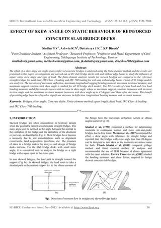
  • 1. IJRET: International Journal of Research in Engineering and Technology eISSN: 2319-1163 | pISSN: 2321-7308 __________________________________________________________________________________________ IC-RICE Conference Issue | Nov-2013, Available @ http://www.ijret.org 50 EFFECT OF SKEW ANGLE ON STATIC BEHAVIOUR OF REINFORCED CONCRETE SLAB BRIDGE DECKS Sindhu B.V1 , Ashwin K.N2 , Dattatreya J.K.3 , S.V Dinesh4 1 Post Graduate Student, 2 Assistant Professor, 3 Research Professor, 4 Professor and Head, Department of Civil Engineering, Siddaganga Institute of Technology, Tumkur sindhubvr@gmail.coml, meetashwinkn@yahoo.com, jk.dattatreya@gmail.com, dineshsv2004@yahoo.com Abstract The effect of a skew angle on single-span reinforced concrete bridges is analyzed using the finite-element method and the results are presented in this paper. Investigations are carried out on RC slab bridge decks with and without edge beams to study the influence of aspect ratio, skew angle and type of load. The finite-element analysis results for skewed bridges are compared to the reference straight bridges for dead load, IRC Class A loading and IRC 70R loading for with and without edge beam. A total of 90 bridge models are analyzed. The variation of maximum deflection, maximum longitudinal sagging bending moment, maximum torsional moment, and maximum support reaction with skew angle is studied for all 90 bridge deck models. The FEA results of Dead load and Live load bending moments and deflections decreases with increase in skew angle, where as maximum support reactions increases with increase in skew angle and the maximum torsional moment increases with skew angle up to 45 degrees and there after decreases. The benefit of providing edge beam is reflected in significant decrease in deflection, longitudinal bending moment and torsional moment. Keywords: Bridges, skew angle; Concrete slabs; Finite element method; span length; dead load; IRC Class A loading and IRC Class 70R loading. ----------------------------------------------------------------------***----------------------------------------------------------------------- 1. INTRODUCTION Skewed bridges are often encountered in highway design when the geometry cannot accommodate straight bridges. The skew angle can be defined as the angle between the normal to the centreline of the bridge and the centreline of the abutment or pier cap, as described in Fig. 2. Skew bridges have become a necessity due to site considerations such as alignment constraints, land acquisition problems, etc. The presence of skew in a bridge makes the analysis and design of bridge decks intricate. For the Slab bridge decks with small skew angle, it is considered safe to analyze the bridge as a right bridge with a span equal to the skew span. In non skewed bridges, the load path is straight toward the support (Fig 1a). In skewed bridges, the load tends to take a shortest path to the nearest support i.e. to the obtuse corners of the bridge here the maximum deflection occurs at obtuse angled corner (Fig 1b). Khaleel et al., (1990) presented a method for determining moments in continuous normal and skew slab-and-girder bridges due to live loads. Menassa et al. (2007) compared the effect o skew angle with reference to straight bridge and reported that the bridges with skew angle less than 20 degree can be designed as non skew as the moments are almost same for both. Vikash Khatri et al. (2012) compared grillage method and finite element method of analysis and recommended the use of FEM because of closes agreement with the exact solution. Patrick Theoret et al., (2012) studied the bending moments and shear forces, required to design skewed concrete slab bridges. (a) (b) Fig1. Direction of moment flow in straight and skewed bridge decks
  • 2. IJRET: International Journal of Research in Engineering and Technology eISSN: 2319-1163 | pISSN: 2321-7308 __________________________________________________________________________________________ IC-RICE Conference Issue | Nov-2013, Available @ http://www.ijret.org 51 Fig2: Skew Bridge 2. PARAMETRIC STUDY A simply supported, single span, two lane RC slab bridge deck is considered. The span is varied from 5, 7.5 and 9.5m (aspect ratio 1) and skew angle is varied from 0° to 60° at 15° interval is considered with the depth of the slab 750mm for all spans. Edge beam of depth 1.5m and width of 0.3m is provided. The bridge deck is analyzed for Dead load as well as two classes of live load i.e. IRC Class A and IRC Class 70R. Comparison of critical structural response parameter of above cases is presented in the following for slabs with and without edge beam. A total of 90 slab deck models have been analyzed Table 1: Geometric parameters slab bridge decks No Span(m) Width(m) Aspect ratio (span/width) 1 5 9.5 0.526 2 7.5 9.5 0.789 3 9.5 9.5 1 3. LOAD ON BRIDGE DECK MODELS The vehicular live load consist of a set wheel loads and are treated as concentrated loads acting at centres of contact areas, two classes of load i.e. IRC Class A and IRC 70R are considered for analysis. The peak values of critical structural response parameter such as deflection, longitudinal sagging bending moment, torsional moment and support reaction are analyzed. Different positions of each type of loading systems are considered from table 2 of IRC 6:2000. 4. FINITE ELEMENT MODELING The analysis is carried out using finite element method. The concrete slabs are modelled using four noded plate elements and edge beams using two noded beam elements. Simple support condition is provided. ELASTIC MODULUS 25000 Mpa POISSON'S RATIO 0.2 DENSITY OF CONCRETE 25kN/m2 5. RESULTS AND DISCUSSION The FEA results are obtained and presented in terms of critical structural response parameter such a deflection, longitudinal sagging bending moment, torsional moment, and support reaction in the bridge deck models due to the applied wheel load. The variations of the critical structural response parameter due to changes in skew angle are presented in the following. 5.1 Deflection • It is observed that the maximum deflection for skewed slab deck for all types of load compared to that of straight deck slab decreases with the increase in skew angle for all aspect ratios as
  • 3. IJRET: International Journal of Research in Engineering and Technology __________________________________________________________________________________________ IC-RICE Conference Issue | Nov-2013, Available @ shown in figure 3. This is because the force flow between the support lines strip area connecting the obtuse angled corners, a skew increases the length of strip area decreases Hence the bending moment and registers significant reduction. • When the deflection for different skew angle and aspect ratios are normalised with respect to the deflection corresponding to zero skew particular aspect ratio. The different in fig 3(a) nearly merge into a single curve as shown in fig 6(a). a) Dead Load (Without Edge Beam c) IRC Class A Load (Without Edge Beam 0 0.2 0.4 0.6 0.8 1 1.2 0 20 40 DEFLECTION(mm) SKEW ANGLE (DEGREES) IJRET: International Journal of Research in Engineering and Technology eISSN: 2319 __________________________________________________________________________________________ 2013, Available @ http://www.ijret.org . This is because the maximum lines is through the strip area connecting the obtuse angled corners, as skew increases the length of strip area decreases. and deflection also When the deflection for different skew angle and aspect ratios are normalised with respect to the deflection corresponding to zero skew of that particular aspect ratio. The different curves as seen 3(a) nearly merge into a single curve as • The normalized deflection i.e. decks without edge beam reduces from unit value to 0.26 f for IRC Class A load, Class 70R load • The deflection of deck slab decreases provision of edge decks without edge reduction in deflection due to the provision of edge beam in the slab bridge deck. Without Edge Beam) b) Dead Load (With Edge Beam Without Edge Beam) d) IRC Class A Load (With Edge Beam 60 SKEW ANGLE (DEGREES) 0.526 0.789 1 0 0.2 0.4 0.6 0.8 0 20 40 DEFLECTION(mm) SKEW ANGLE (DEGREES) eISSN: 2319-1163 | pISSN: 2321-7308 __________________________________________________________________________________________ 52 The normalized deflection i.e. Dα/D0 for slab decks without edge beams for all aspect ratios reduces from unit value to 0.26 for dead load and IRC Class A load, unit value to 0.64 for IRC 70R load. he deflection of deck slab decreases with the provision of edge beam compared to the slab without edge beam. There is nearly 10% reduction in deflection due to the provision of edge beam in the slab bridge deck. With Edge Beam) With Edge Beam) 40 60 SKEW ANGLE (DEGREES) 0.526 0.789 1
  • 4. IJRET: International Journal of Research in Engineering and Technology __________________________________________________________________________________________ IC-RICE Conference Issue | Nov-2013, Available @ e) IRC Class70R Load (Without Edge Beam) f) IRC Class 70R Load (With Edge Beam) Fig 3 Variation of Deflection Due To Dead Load 5.2 Longitudinal Bending Moment • The trend in longitudinal bending moment is similar to deflection. It is observed that the maximum dead load longitudinal bending moment and longitudinal bending moment for skewed compared to that of straight deck slab decreases with the increase in skew angle for all aspect ratios shown in fig 4. This is because the force flow between the support lines is through the strip area connecting the obtuse angled corners, as skew increases the length of strip area decreases therefore the moment decreases. • When the longitudinal bending moment for differen skew angle and aspect ratios are normalised with a) Dead Load (Without Edge Beam) b) Dead Load (With Edge Beam) 0 0.5 1 1.5 0 20 40 DEFLECTION(mm) SKEW ANGLE (DEGREES) -250 -200 -150 -100 -50 0 0 20 40 LongitudinalSagging BendingMoment(kNm) Skew Angle (Degrees) IJRET: International Journal of Research in Engineering and Technology eISSN: 2319 __________________________________________________________________________________________ 2013, Available @ http://www.ijret.org e) IRC Class70R Load (Without Edge Beam) f) IRC Class 70R Load (With Edge Beam) Deflection Due To Dead Load and Live Load on Deck Slab without The trend in longitudinal bending moment is similar It is observed that the maximum dead longitudinal bending moment and wheel load for skewed deck slabs compared to that of straight deck slab decreases with for all aspect ratios as This is because the force flow between the support lines is through the strip area connecting the obtuse angled corners, as skew increases the length of strip area decreases therefore When the longitudinal bending moment for different skew angle and aspect ratios are normalised with respect to the longitudinal bending moment corresponding to zero skew of that particular aspect ratio. The different curves as seen in fig 4(a) nearly merge into a single curve as shown in fig 6(b). • The normalized longitudinal bending moment i.e. Mα/M0 varies from unity to without edge beam IRC Class A load and unity to 0.79 for IRC Class 70R load for all aspect ratios. • The longitudinal bending moment provision of edge beam for both dead load and wheel load compared to without edge beam. There 10% reduction in to the provision of edge beam in the slab bridge deck. a) Dead Load (Without Edge Beam) b) Dead Load (With Edge Beam) 60 SKEW ANGLE (DEGREES) 0.526 0.789 1 0 0.2 0.4 0.6 0.8 1 0 20 40 DEFLECTION(mm) SKEW ANGLE (DEGREES) 40 60 Skew Angle (Degrees) 0.526 0.789 1 -160 -140 -120 -100 -80 -60 -40 -20 0 0 20 LongitudinalSagging BendingMoment(kNm) Skew Angle (Degrees) eISSN: 2319-1163 | pISSN: 2321-7308 __________________________________________________________________________________________ 53 e) IRC Class70R Load (Without Edge Beam) f) IRC Class 70R Load (With Edge Beam) without and With Edge Beams respect to the longitudinal bending moment corresponding to zero skew of that particular aspect ratio. The different curves as seen in fig 4(a) nearly merge into a single curve as shown in fig 6(b). rmalized longitudinal bending moment i.e. varies from unity to 0.33 for deck slabs out edge beam for dead load, unity to 0.74 for IRC Class A load and unity to 0.79 for IRC Class 70R load for all aspect ratios. The longitudinal bending moment decreases with the provision of edge beam for both dead load and wheel load compared to without edge beam. There is almost 10% reduction in longitudinal bending moment due to the provision of edge beam in the slab bridge deck. a) Dead Load (Without Edge Beam) b) Dead Load (With Edge Beam) 40 60 SKEW ANGLE (DEGREES) 0.526 0.789 1 40 60 Skew Angle (Degrees) 0.526 0.789 1
  • 5. IJRET: International Journal of Research in Engineering and Technology __________________________________________________________________________________________ IC-RICE Conference Issue | Nov-2013, Available @ c) IRC Class A Load (Without Edge Beam) d) IRC Class A Load (With Edge Beam) e) IRC Class70R Load (Without Edge Beam) f) IRC Class 70R Load (With Edge Fig 4 Variation of Longitudinal Bending Moment 5.3 Torsional Moment • The dead load and wheel load torsional skewed deck slab increases with the increase in skew angle for all aspect ratios up to 45 decreases for further increase in skew angle • The Torsional moment for different skew angle and aspect ratios are normalised with respect to the Torsional moment corresponding to zero skew of that particular aspect ratio. The different curves as seen in fig 5(a) nearly merge into a single curve as shown in fig 6(c). -160 -120 -80 -40 0 0 20 40 LongitudinalSaggingBending Moment(kNm) Skew Angle (Degrees) -140 -120 -100 -80 -60 -40 -20 0 0 20 40 LongitudinalSagging BendingMoment(kNm) Skew Angle (Degrees) IJRET: International Journal of Research in Engineering and Technology eISSN: 2319 __________________________________________________________________________________________ 2013, Available @ http://www.ijret.org c) IRC Class A Load (Without Edge Beam) d) IRC Class A Load (With Edge Beam) e) IRC Class70R Load (Without Edge Beam) f) IRC Class 70R Load (With Edge Variation of Longitudinal Bending Moment Due To Dead Load and Live Load on Deck Slab Without and With Edge Beams load torsional moments for with the increase in skew up to 45 degrees and then for further increase in skew angle. for different skew angle and aspect ratios are normalised with respect to the corresponding to zero skew of that particular aspect ratio. The different curves as seen in single curve as shown in • The normalized Torsional moment i.e. TM increases from unity to from 2.36 to 1.84 for 45° to 60° without edge beam for dead load, unity to 45° and 3.2 for 60° 1.5 up to 45° and 0.9 for 60° for all aspect ratios. • The torsional moment decrea edge beam for both dead load and compared to without edge beam. reduction in Torsional moment due to the provision of edge beam in the slab bridge deck. 60 Skew Angle (Degrees) 0.526 0.789 1 -80 -60 -40 -20 0 0 20 LongitudinalSaggingBending Moment(kNm) Skew Angle (Degrees) 60 Skew Angle (Degrees) 0.526 0.789 1 -120 -100 -80 -60 -40 -20 0 0 20 LongitudinalSagging BendingMoment(kNm) Skew Angle (Degrees) eISSN: 2319-1163 | pISSN: 2321-7308 __________________________________________________________________________________________ 54 c) IRC Class A Load (Without Edge Beam) d) IRC Class A Load (With Edge Beam) e) IRC Class70R Load (Without Edge Beam) f) IRC Class 70R Load (With Edge Beam) n Deck Slab Without and With Edge Beams The normalized Torsional moment i.e. TMα/TMo from unity to 3.33 up to 30° and decreases 2.36 to 1.84 for 45° to 60° for deck slabs without edge beam for dead load, unity to 3.5 up to 45° and 3.2 for 60° for IRC Class A load and unity to 1.5 up to 45° and 0.9 for 60°for IRC Class 70R load for all aspect ratios. The torsional moment decreases with the provision of edge beam for both dead load and wheel load compared to without edge beam. There is almost 50% reduction in Torsional moment due to the provision of edge beam in the slab bridge deck. 40 60 Skew Angle (Degrees) 0.526 0.789 1 40 60 Skew Angle (Degrees) 0.526 0.789 1
  • 6. IJRET: International Journal of Research in Engineering and Technology __________________________________________________________________________________________ IC-RICE Conference Issue | Nov-2013, Available @ a) Dead Load (Without Edge Beam) b) Dead Load (With Edge Beam) c) IRC Class A Load (Without Edge Beam) d) IRC Class A Load (With Edge Beam) e) IRC Class70R Load (Without Edge Beam) f) IRC Class 70R Load (With Edge Beam) Fig 5 Variation of Torsional Moment of Deck Slab 5.4 Support Reaction at Obtuse Angled Corner. • The maximum dead load and wheel reactions at the obtuse angled corner of deck slab increases with increase in skew angle table 2, 3 and 4. The reactions at the obtuse angled 0 10 20 30 40 50 60 70 0 20 40 TORSIONALMOMENT (kNm) SKEW ANGLE (DEGREES) 0 10 20 30 40 50 0 20 40 TORSIONALMOMENT (kNm) SKEW ANGLE (DEGREES) 0 10 20 30 40 50 0 20 40 60 TORSIONALMOMENT (kNm) SKEW ANGLE (DEGREES) IJRET: International Journal of Research in Engineering and Technology eISSN: 2319 __________________________________________________________________________________________ 2013, Available @ http://www.ijret.org (Without Edge Beam) b) Dead Load (With Edge Beam) c) IRC Class A Load (Without Edge Beam) d) IRC Class A Load (With Edge Beam) e) IRC Class70R Load (Without Edge Beam) f) IRC Class 70R Load (With Edge Beam) Variation of Torsional Moment of Deck Slab with Skew Angle Obtuse Angled Corner. wheel load support reactions at the obtuse angled corner of deck slab angle as shown in The reactions at the obtuse angled end of slab support are larger than other end, the increase in value over average value ranging from 0 to 50% for skew angle of 15 to 45°. around 80 %, when it reaches bridge. 60 SKEW ANGLE (DEGREES) 0.526 0.789 1 0 5 10 15 20 25 30 35 40 0 20 40 TORSIONALMOMENT (kNm) SKEW ANGLE (DEGREES) 60 SKEW ANGLE (DEGREES) 0.526 0.789 1 0 5 10 15 20 25 30 35 40 0 20 40 TORSIONALMOMENT (kNm) SKEW ANGLE (DEGREES) 60 SKEW ANGLE (DEGREES) 0.526 0.789 1 0 5 10 15 20 25 30 0 20 40 TORSIONALMOMENT (kNm) SKEW ANGLE (DEGREES) eISSN: 2319-1163 | pISSN: 2321-7308 __________________________________________________________________________________________ 55 (Without Edge Beam) b) Dead Load (With Edge Beam) c) IRC Class A Load (Without Edge Beam) d) IRC Class A Load (With Edge Beam) e) IRC Class70R Load (Without Edge Beam) f) IRC Class 70R Load (With Edge Beam) Skew Angle end of slab support are larger than other end, the increase in value over average value ranging from 0 to 50% for skew angle of 15 to 45°. It increases around 80 %, when it reaches 60° compared to right 40 60 SKEW ANGLE (DEGREES) 0.526 0.789 1 40 60 SKEW ANGLE (DEGREES) 0.526 0.789 1 40 60 SKEW ANGLE (DEGREES) 0.526 0.789 1
  • 7. IJRET: International Journal of Research in Engineering and Technology eISSN: 2319-1163 | pISSN: 2321-7308 __________________________________________________________________________________________ IC-RICE Conference Issue | Nov-2013, Available @ http://www.ijret.org 56 • The normalized Support reaction i.e. Sα/S0 varies from unity to 7 for deck slabs without edge beam for dead load, unity to 8 for IRC Class A load and unity to 10 for IRC Class 70R load for all aspect ratios. • The support reaction increases when edge stiffening beam is provided with comparison of the deck slabs without edge beams. There is almost 10% increase in support reactions due to the provision of edge beam in the slab bridge deck. Table 2: Dead Load Support reaction Maximum Support Reaction(kN) Aspect Ratio 0.526 0.789 1 Skew Angle Without Edge Beam With Edge Beam Without Edge Beam With Edge Beam Without Edge Beam With Edge Beam 0 7.913 20.916 14.676 43.524 21.198 97.274 15 13.202 31.551 27.077 60.061 42.296 96.171 30 21.853 35.823 51.272 79.662 84.355 130.331 45 30.903 40.58 75.019 93.637 126.489 156.137 60 35.348 37.835 84.406 89.735 144.521 152.775 Table 3: IRC Class A Loading Support reaction Maximum Support Reaction(kN) Aspect Ratio 0.526 0.789 1 Skew Angle Without Edge Beam With Edge Beam Without Edge Beam With Edge Beam Without Edge Beam With Edge Beam 0 59.638 59.652 35.869 35.8 60.377 60.306 15 100.005 123.835 70.339 122.844 117.931 170.474 30 87.017 179.89 102.37 168.405 148.312 157.188 45 119.443 151.391 235.305 233.78 178.517 188.794 60 234.563 233.313 286.926 315.778 471.076 438.737 Table 4: IRC Class 70R Loading Support reaction Maximum Support Reaction(kN) Aspect Ratio 0.526 0.789 1 Skew Angle Without Edge Beam With Edge Beam Without Edge Beam With Edge Beam Without Edge Beam With Edge Beam 0 44.863 44.851 43.767 43.679 42.5 42.5 15 163.38 163.411 195.326 186.26 176.343 175.653 30 170.261 170.273 168.77 169.017 169.293 169.561 45 166.008 235.094 157.151 202.951 161.976 185.883 60 164.924 289.43 164.799 406.386 172.906 418.8
  • 8. IJRET: International Journal of Research in Engineering and Technology __________________________________________________________________________________________ IC-RICE Conference Issue | Nov-2013, Available @ (a) Fig 6 Variation of Normalised values of deflection, longitudinal moment and Torsional Moment of Deck Slab with Skew Angle CONCLUSIONS 1) The maximum deflection for skewed deck slabs decreases with the increase in skew angle for all aspect ratios and at 60° the reduction is around Bridge without edge beam and about seen for slabs with edge beam when compared to bridge without edge beam for all aspect ratio load. A similar trend is observed in case of wheel load but the order of reduction is comparatively less i.e. about 40 % to 50% compared to the case of dead load. 2) Longitudinal bending moment shows similar pattern of reduction with increase in skew angle and maximum reduction due to dead load is found to be 70 % skew angle 60° compared to right bridge beam for all aspect ratio; When edge beam is provided it decreases around 75% for a skew angle to right bridge without edge beam for all aspect Maximum wheel load longitudinal bending moment decreases around 30 % to 35% for skew angle compared to right bridge for all aspect ratio. 3) For right bridge deck slab (0° skew), maximum longitudinal sagging moments are orthogonal to abutments in central region. As the skew angle 0 0.2 0.4 0.6 0.8 1 1.2 0 20 40 60 Dα/D0 Skew Angle (Degrees) 0 0.5 1 1.5 2 2.5 3 3.5 TMα/TMo IJRET: International Journal of Research in Engineering and Technology eISSN: 2319 __________________________________________________________________________________________ 2013, Available @ http://www.ijret.org (a) (c) Variation of Normalised values of deflection, longitudinal moment and Torsional Moment of Deck Slab with Skew Angle The maximum deflection for skewed deck slabs decreases with the increase in skew angle for all aspect and at 60° the reduction is around 75 % in Slab 90% reduction is when compared to right for all aspect ratio for dead A similar trend is observed in case of wheel load but the order of reduction is comparatively less i.e. about 40 % to 50% compared to the case of dead load. ows similar pattern of reduction with increase in skew angle and maximum is found to be 70 % for a 60° compared to right bridge without edge for all aspect ratio; When edge beam is provided for a skew angle 60° compared to right bridge without edge beam for all aspect ratio. longitudinal bending moment for skew angle 60° ght bridge for all aspect ratio. For right bridge deck slab (0° skew), maximum longitudinal sagging moments are orthogonal to abutments in central region. As the skew angle increases maximum longitudinal moments gradually shifts towards obtus 4) Torsional moment is found to be around 30% to 35% corresponding longitudinal bending moment. In contrast to longitudinal bending and deflection torsional moment shows continuous increase in magnitude up to skew angle of 45° and there after a re magnitude. The peak value of torsional moment is at 45° and is two times more than corresponding value for a right bridge deck. 5) For right bridge deck slabs (0° skew), maximum torsional moments are located near all corner regions. As skew angle increases torsional moments gradually shifts towards obtuse angle. 6) The peak value of support reaction is observed at obtuse angled corner and the magnitude of reaction with increase in skew angle angled end of slab support are larger than other end, the increase in value over average value ranging from 0 to 50% for skew angle of 15 to 45°. It increases around 80 %, when it reaches 60° compared to right bridge. 7) The advantage of providing the reduction of the maximum torsional, maximum 0.526 0.789 1 0 0.2 0.4 0.6 0.8 1 1.2 0 20 40 Mα/Mo Skew Angle (Degrees) 0 20 40 60 Skew Angle (Degrees) 0.526 0.789 1 eISSN: 2319-1163 | pISSN: 2321-7308 __________________________________________________________________________________________ 57 (a) (b) Variation of Normalised values of deflection, longitudinal moment and Torsional Moment of Deck Slab with Skew Angle increases maximum longitudinal moments gradually shifts towards obtuse angle. Torsional moment is found to be around 30% to 35% of corresponding longitudinal bending moment. In contrast to longitudinal bending and deflection torsional moment shows continuous increase in magnitude up to skew angle of 45° and there after a reduction in magnitude. The peak value of torsional moment is at 45° and is two times more than corresponding value for For right bridge deck slabs (0° skew), maximum torsional moments are located near all corner regions. increases torsional moments gradually shifts towards obtuse angle. The peak value of support reaction is observed at obtuse angled corner and the magnitude of reaction increases with increase in skew angle. The reactions at the obtuse support are larger than other end, the increase in value over average value ranging from 0 to 50% for skew angle of 15 to 45°. It increases around 80 %, when it reaches 60° compared to right bridge. The advantage of providing edge beam is reflected in the maximum torsional, maximum 60 Skew Angle (Degrees) 0.526 0.789 1
  • 9. IJRET: International Journal of Research in Engineering and Technology eISSN: 2319-1163 | pISSN: 2321-7308 __________________________________________________________________________________________ IC-RICE Conference Issue | Nov-2013, Available @ http://www.ijret.org 58 longitudinal sagging moment and maximum deflection. deflection decreases around 40% to 60% for skew angle up to 60°, longitudinal bending moment decreases around 60% to 70% for skew angle up to 60°, the reduction is even more pronounced in case of torsional moment, support reaction increases around 170% when it reaches 45° and then decreases by 14% for 60° skew angle compared to right bridge without edge beam for all aspect ratio. REFERENCES [1] C. Menassa; M. Mabsout; K. Tarhini; and G. Frederick, Influence of Skew Angle on Reinforced Concrete Slab Bridges, Journal of Bridge Engineering, Vol. 12, No. 2, March 1, 2007. ©ASCE, pp 205-214. [2] Ibrahim S. I. Harba, Effect of Skew Angle on Behaviour of Simply Supported R. C. T-Beam Bridge Decks, ARPN Journal of Engineering and Applied Sciences vol. 6, no. 8, august 2011, pp 1-14. [3] Patrick Théoret; Bruno Massicotte; and David Conciatori, Analysis and Design of Straight and Skewed Slab Bridges, Journal of Bridge Engineering, Vol. 17, No. 2, March 1, 2012. ©ASCE, pp289–301. [4] Gholamreza Nouri, Ph.D.1; and Zahed Ahmadi, M.Sc.2, Influence of Skew Angle on Continuous Composite Girder Bridge, Journal of Bridge Engineering, Vol. 17, No. 4, July 1, 2012. ©ASCE, pp 617–623. CODES 1. IRC 6:2000 “Standard Specifications and Code of Practice for Road Bridges, Section-II Loads and Stresses”, Indian Road Congress, New Delhi. 2. IRC 21:2000 “Standard Specifications and Code of Practice for Road Bridges, Section-III Cement Concrete (Plain and Reinforced)”, Indian Road Congress, New Delhi.