Since cables are the most expensive equipment in an installation, they must be thoroughly tested using the methods listed above. This setup is just with two-wire continuity tests and may be used throughout the switching matrix.
• The purposeof power cable testing is to guarantee that the cable’s insulation is
intact and that they operate correctly. Durability, high-voltage resistance, and
partial discharge detection are tested. Poor installation causes 99 percent of cable
issues during new electrical equipment commissioning.
• Power cable suppliers in UAE do rigorous testing to ensures that any potential
flaws are addressed before they cause more harm. They provide cable protection
from minor lacerations to punctures that result in current discharge.
3.
Why Test Cables?
–Cable conformity
– Cabling quality
– Cable functionality
• A cable fault may often be identified before it becomes a problem.
• A visual inspection of your facility's wiring might uncover issues before they cause
downtime. We look for copper corrosion, insulation cracks, dampness on wires,
and other indicators of cable degradation.
• It is critical to ensure that cables and couplings are in great operating order and
that cable problem are detected immediately.
• Cable testing should be a priority for Power cable suppliers in UAE to prevent and
solve issues. Even with a range of test techniques and equipment, cable testing
may be a challenging operation.
• As a result, choosing and operating the best test equipment is as important as the
test equipment itself.
4.
What Happens WhenCables Are
Tested?
• The tests and inspections required before energizing 600V or less low voltage
cable are given below.
– Compare the cable data to the drawings and specs.
– Think about the number of sets and their insulation ratings.
– Examine exposed cable portions for material degradation. Inspect the cable
jacket and exposed insulation for damage.
– Verify that the single-line diagram's connecting points match.
– Check for excessive resistance using a calibrated torque wrench, low-
resistance ohmmeter, or thermographic survey.
– ANSI/NETA Table 100.12 US Standard Fasteners, Bolt Torque Values for
Electrical Connections
– Using a low resistance ohmmeter, compare the values of equivalent bolted
connections to find which one moves more than 50% of the lowest value.
– Examine the exposed cable jacket and insulation on low voltage wire and
cable.
– Before checking compression-applied connections, ensure the connector is
rated for the cable size and has the appropriate indentations.
5.
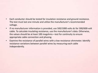
• Each conductorshould be tested for insulation resistance and ground resistance.
The test must last one minute and utilize the manufacturer's recommended
voltage.
• If no manufacturer information is provided, use 500/1000 volts dc for 300/600-volt
cable. To calculate insulating resistance, use the manufacturer's data. Otherwise,
the values should be at least 100 megohms—test for continuity to ensure
appropriate cable connection and phasing.
• Examine the resistance of parallel wires with a low-resistance ohmmeter. Identify
resistance variations between parallel wires by measuring each cable
independently.
6.
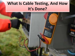
How Is CableTesting Done?
• Power cable suppliers test the following things to avoid leakage:
• Continuity Check
– The continuity test measures the low resistance of cables from 1 to 250
meters in length.
– The continuity test can be done with two or four wires, depending on the
resistance to be measured.
– It includes injecting a preset current and measuring the resistance's terminals
for voltage and current. Ohm’s law will decide that.
– Divide the switching matrix into two internal buses using the Kelvin technique.
– Directing the test current
– transmitting voltage between the element's terminals
– Opposing points are allocated to the measurement's SENSE and current
injection. This setup is suitable with two-wire continuity tests and may be
used throughout the switching matrix.
7.
Insulation Testing
– Ahigh resistance test (insulation) is usually done in DC.
– This test is combined with a short circuit and high voltage test in DC.
– The insulation test has several uses.
• The insulation test can reveal:
• calculating high voltage insulating resistances from 50-kilo ohm to 2000 megaohm
• Detection of short circuits and dielectric
• So, here's how it works:
– A low-voltage test (continuity measurement) detects short circuits (1). If a
short circuit is found, the insulation test fails (the message SHORT CIRCUIT
appears in the error list).
– If there is no short, the high voltage is applied. Breakdown happens within the
increasing time and the test is stopped (the breakdown voltage is given in the
error list).
8.
– If thereis no breakdown and the voltage does not reach the required level,
the message UUprog displays (ten percent).
– The voltage is then supplied for the set time
– If a failure occurs within this period, the test is terminated, and the error time
is displayed.
– To conclude the application time, the insulation test is done, and the
insulation resistance is measured
– (4). An extra measurement time is added depending on the intended range.
The measurement time varies from 20ms - 240ms.
• To finish the test, the tester lowers the high voltage and discharges the object to
the ground (total time 20ms).
• Every insulation measurement ends with this step.
• The dielectric strength test detects any rapid shift in the current test increase
outside the specified limit.
• Short circuit and high voltage testing can be disabled.
9.
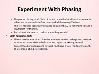
Experiment With Phasing
–The proper phasing of all LV circuits must be verified at all locations where LV
cables are terminated into fuse bases and while moving LV cables.
– This test requires specifically designed equipment. A 240-volt mains voltage is
insufficient for this test.
– For this test, the neutral conductor must be grounded.
• Earth Resistance Test:
– The earth resistance of an LV feeder in an overhead or underground network
must be less than 10 ohms before connecting to the existing network.
– Any overhead or underground network must have a total resistance to earth
of less than 1 ohm before joining.
10.
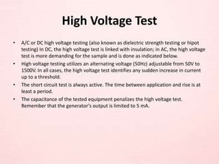
High Voltage Test
•A/C or DC high voltage testing (also known as dielectric strength testing or hipot
testing) In DC, the high voltage test is linked with insulation; in AC, the high voltage
test is more demanding for the sample and is done as indicated below.
• High voltage testing utilizes an alternating voltage (50Hz) adjustable from 50V to
1500V. In all cases, the high voltage test identifies any sudden increase in current
up to a threshold.
• The short circuit test is always active. The time between application and rise is at
least a period.
• The capacitance of the tested equipment penalizes the high voltage test.
Remember that the generator's output is limited to 5 mA.
11.
The Advantages ofCable Testing
• Limited product warranties are available.
• Repair is more costly than testing.
• Testing regularly will ensure that the infrastructure is future-proof.
12.
Conclusion
• Since cablesare the most expensive equipment in an installation, they must be
thoroughly tested using the methods listed above.
• Power cable suppliers install the cable in the proper directions, particularly in
curvatures, to avoid bending and kinking and improve power transmission and
avoid losses during transmission, thereby increasing the cable's reliability and
suspension.
13.
https://www.urgroupuae.com/
+971 6 5341245/
+971 6 5348425
Support:
info@urgroupuae.com
admin@urgroupuae.com
Wadi Al Rafesa Street, Shed no 177/1,
Near Dyna Trade, PO Box 47260 Sharjah
- UAE