1. KCES’s COEIT, Jalgaon
Department of Electronics and Telecommunication
Subject In-Charge: Asst. Prof. C. S. Thombre (EXTC)
Aim:- Design and test a band reject filter using op-amp.
a.Plot frequency response.
Apparatus: Breadboard, resistances, Capacitors, IC741, connecting wires, probes etc
Theory: A band pass filter (also called as band stop or band elimination filter) can be either Narrow band
reject filter or Wide band reject filter. Narrow band reject filter has very narrow stop band thus it is also
called a notch filter. It is commonly used for attenuation of a single frequency such as 60 Hz power line
frequency hum. One simple technique to make notch filter is to subtract the band pass filter output from
its input. But another method for implementing notch filter is most widely used which the twin-T network
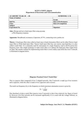
is illustrated in diagram below.
Diagram: Practical Twin-T Notch Filter
This is a passive filter composed of two T-shaped networks. One T-network is made up of two resistors
and a capacitor, while the other is made of two capacitors and a resistor.
The notch out frequency (fN) is the frequency at which maximum attenuation occurs is given by
=
1
2
One drawback of above notch filter (passive twin-T network) is that it has relatively low figure of merit
Q. However, Q of the network can be increased significantly if it is used with the voltage follower, as
illustrated in diagram below.
ACADEMIC YEAR: 20 - 20 SEMISTER: I / II
Name of student
Grade
Roll No Date of Performance
Class Date of Completion
Subject
Experiment No Signature
2. KCES’s COEIT, Jalgaon
Department of Electronics and Telecommunication
Subject In-Charge: Asst. Prof. C. S. Thombre (EXTC)
Diagram: Modified Twin-T Notch Filter for Q
The transfer function of notch filter (modified circuit where the output of the voltage follower is supplied
back to the junction of R/2 and 2C) is given by
( ) = =
+
+ + 4(1 − )
Where, = and = ,
For steady state we can rewrite transfer fuction by replacing s=jω as follows
( ) =
+
− − 4(1 − )
Where = =⁄ 1 , i.e.
=
1
2
The 3db bandwidth is given by,
= − = 4(1 − )
And
=
As K approaches to unity, Q becomes very large and BW approaches to 0. But a practical mismatch
between resistors and capacitors limits Q and BW to practically realizable value. The frequency response
of the active notch filter is shown in diagram below:
Diagram: Frequency Response of Twin-T Notch Filter
Notch filters are most commonly used in communications and biomedical instruments for eliminating the
undesired frequencies.
3. KCES’s COEIT, Jalgaon
Department of Electronics and Telecommunication
Subject In-Charge: Asst. Prof. C. S. Thombre (EXTC)
Design a band reject filter using op-amp for __Hz.
Procedure:-
1. Mount all the components on the bread board as per the circuit diagram.
2. Apply the DC voltage of +15V & -15V from power supply.
3. Apply the input voltage 1V (p-p) & 1 kHz frequency at the input terminal.
4. Observe the output on CRO
5. Write output voltage amplitude in observation table and draw frequency response..
Observation Table:-
Frequency Vo Av =Vo/Vi Av(db)=20log(Vo/Vi)
4. KCES’s COEIT, Jalgaon
Department of Electronics and Telecommunication
Subject In-Charge: Asst. Prof. C. S. Thombre (EXTC)
Result:-
Cut off frequency Theoretically Practically
Conclusion:-