1. Fredrick Kendrick ITT Technical Engineering ET2530 1
IC Circuits / Amplifiers
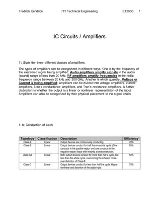
1). State the three different classes of amplifiers:
The types of amplifiers can be categorized in different ways. One is by the frequency of
the electronic signal being amplified; Audio amplifiers amplify signals in the audio
(sound) range of less than 20 kHz, RF amplifiers amplify frequencies in the radio
frequency range between 20 kHz and 300 GHz. Another is which quantity, Voltage or
Current is being amplified; amplifiers can be divided into voltage amplifiers, current
amplifiers, Tran’s conductance amplifiers, and Tran’s resistance amplifiers. A further
distinction is whether the output is a linear or nonlinear representation of the input.
Amplifiers can also be categorized by their physical placement in the signal chain.
1. b: Conduction of each:
3. Fredrick Kendrick ITT Technical Engineering ET2530 3
Class A
100% of the input signal is used (conduction angle Θ = 360°). The active element
remains conducting all of the time.
Class B
50% of the input signal is used (Θ = 180°); the active element carries current half of
each cycle, and is turned off for the other half.
4. Fredrick Kendrick ITT Technical Engineering ET2530 4
Class AB
Class AB is intermediate between class A and B, the two active elements conduct more
than half of the time.
Class C
Less than 50% of the input signal is used (conduction angle Θ < 180°).
A "Class D" amplifier uses some form of pulse-width modulation to control the output
devices; the conduction angle of each device is no longer related directly to the input
signal but instead varies in pulse width. These are sometimes called "digital" amplifiers
because the output device is switched fully on or off, and not carrying current
proportional to the signal amplitude.
5. Fredrick Kendrick ITT Technical Engineering ET2530 5
1. c: Amplifier Classes and Efficiency:
2). How is Crossover distortion eliminated in Class B:
6. Fredrick Kendrick ITT Technical Engineering ET2530 6
The top half of the waveform comes from TR1 conducting and the bottom half from TR2
conducting. At some point a class B amplifier changes from using the top transistor to
the bottom transistor. When this happens there is insufficient voltage across
base/emitter to activate either transistor hence there is a dead zone:
The diodes turn a class B design into a class AB. Now, neither transistor is fully
off therefore the dead zone is no more.
The capacitors are incidental - they allow the input signal to couple to both bases
without the new biasing arrangement being affected.
3). What criteria determine the type of oscillator that may be used in electronic circuits:
An oscillator is an electronic device for generating an AC signal voltage. Oscillators
generate sinusoidal or non-sinusoidal waveform from very low frequencies up to very
7. Fredrick Kendrick ITT Technical Engineering ET2530 7
high frequencies. The local oscillator in most present-day broadcast band AM super
heterodynes will cover a range of frequencies from 1000 to 2100 KHz (approximately).
An oscillator is a circuit to generate alternating voltage of desired frequency and
amplitude. It converts DC energy to an AC voltage. It has wide applications: i.e. to test a
stereo amplifier; an audio signal generator generates 20 KHz to 15 kHz at the
transmitter and 47 MHz to 20 MHz for TV broadcasting in radio and TV receiver’s high
frequency oscillators are required.
Basically an oscillator circuit is an amplifier that provides itself (through feedback) with
an input signal. It is a non-rotating device for producing alternating current, the output
frequency of which is determined by the characteristics of the device. The initial purpose
of an Oscillator is to generate a given waveform of a constant peak amplitude and
specific frequency and to maintain this waveform within certain limits of amplitude and
frequency.
Oscillator Block Diagram
4). State the two requirements of an Oscillator: (Barkhausen Criteria)
The Barkhausen Criterion X1 and X2 must be of the same type, while X3 must be
opposite. In its basic form it uses three reactance: X1, X2 and X3 in its feedback
network. The LC tank circuit produces the oscillations.
8. Fredrick Kendrick ITT Technical Engineering ET2530 8
5). Complete the following table by finding the unknown:
Resonant Frequency Inductance Capacitance
Added Note: 1 / 2π√LC Added Note: XL = 2πXL Added Note: 1 / 2πfc
150 MHz 12.5µH .09pfd
15MHz 3.3µH / 11.78kΩ 33pfd
285MHz 113nH 2.7pfd
6). A parallel resonant circuit has an (Inductance) L = 22µH, (Capacitance) C = 58pfd
and a winding resistance of (Resonant Freq.) fr = 3.7Ω (Determine): 4.4554830359378
= 4.45 Megahertz.
a).Resonant Frequency: 4.45MHz (fr = 1 / 2π√LC) (1/ 2π√3-3MH x 0.47-6 µf) = 4.24
b). Q: 166 (XL = 2π fL) (Q = XL / R = 2π x 4.24kHz x 3-3 mH = 79.9Ω /2Ω = 39.9)
c). Zmax: 102 kΩ (Q2 x R = (39.9)2 x 2Ω = 3.19kΩ)
d). Bandwidth: 26.8 kHz (BW = R / 2πL = 2Ω / 2π x 3-3 mH = 106 Hz)
e). Lower Cutoff Frequency: 4.4634 mHz (Freq – BW)
f). Upper Cutoff Frequency: 4.4366 mHz (Freq + BW)
7). Explain the difference between the Hartley, Colpitts and Clapp Oscillator:
(Three-Point Type of Oscillators)
7. a: Hartley: The advantage of the Hartley Oscillator is that the oscillator is easily
excited. Its disadvantage is that two inductors or one tapped inductor must be employed
and that its phase noise is higher than that of other types of oscillators.
7. b: Colpitts: The advantage of the Colpitts is that only one inductor is needed and that
its phase noise is much lower than that of the Hartley and Clapp.
7. c: Clapp: The Clapp oscillator is a modified Colpitts oscillator. The improvement is
that the frequency bandwidth is more easily covered by adjusting one of the two
Capacitors.
9. Fredrick Kendrick ITT Technical Engineering ET2530 9
8). What is meant by the “Q” of a LC band pass filter? Why is this important?
8. a: Crystal filters find many applications in communications because they can be
designed to exhibit very high values of Q. As one example, the crystal filter is commonly
used in single- sideband systems to attenuate the unwanted sideband.
8. b: Because of its very high Q, the crystal filter passes a much narrower band of
frequencies than the best LC filter. Crystals with a Q up to about 50,000 are available.
(Beasley 113)
9). What electronic part provides a very stable frequency of an Oscillation:
(Q-Factor and Frequency Stability of a Crystal)
The crystal has a very high value of Q-factor as compared to the discrete LC tank
circuits. For example, the Q-factor of a typical crystal is 20,000 as compared to a
maximum of about 100 for high quality LC tank circuits. The extremely high value of the
Q-factor of a crystal produces oscillators with a very stable frequency values.
References:
Beasley, Jeffrey S., Jonathan Hymer, Gary Miller. Electronic Communications: A
System Approach. Pearson Custom Publishing, 2014. Vital Book file.
The citation provided is a guideline. Please check each citation for accuracy before use