SlideShare a Scribd company logo
1 of 15
Download to read offline
Hydraulics 3 Waves: Transformation – 1 Dr David Apsley
2. WAVE TRANSFORMATION AUTUMN 2022
This section will look at the following wave transformations as waves approach a coastline:
Refraction – change of direction as oblique waves move into shallower water;
Shoaling – change of height as waves move into shallower water;
Breaking – collapse of waves after steepening;
Diffraction – spreading of waves into a region of shadow;
Reflection – reversal of direction at a boundary, often combining to form a standing wave.
2.1 Refraction
Refraction is the bending of waves toward the normal as they move into shallower water.
Waves may approach a coastline at an angle θ, defined as the angle between wave crests and
the depth contours, or between the corresponding normals (for the wave, also called rays or
orthogonals).
As waves move toward a coastline:
• their period remains constant;
• their wavelength changes (because the depth changes);
and hence:
• their speed changes.
Refraction (which occurs with other wave phenomena, notably in optics) is the change in
direction with wave speed.
2.1.1 Snell’s Law
Consider a discrete depth change ℎ1 → ℎ2, with corresponding phase-speed change 𝑐1 → 𝑐2.
Look at the region where two successive wave crests cross the depth change. From the diagram,
since the period of waves is not changed, distances AB and A′ B′ between successive wave
crests are covered in the same time 𝑇:
B
A
A' B'
h (shallower)
2
h1
1
2
1
w
a
v
e
c
r
e
s
t
o
r
t
h
o
g
o
n
a
l
d
2
Hydraulics 3 Waves: Transformation – 2 Dr David Apsley
𝑇 =
distance
speed
=
𝑑 sin 𝜃1
𝑐1
=
𝑑 sin 𝜃2
𝑐2
Hence,
sin 𝜃1
𝑐1
=
sin 𝜃2
𝑐2
In reality, depth (and hence speed) change as waves approach the shore is gradual rather than
sudden. However, it can still be imagined as a series of such small steps. Thus, refraction is
governed by Snell’s law:
sin 𝜃
𝑐
= constant
or, in terms of wavenumber (since 𝑐 = 𝜔 𝑘
⁄ , and frequency 𝜔 is unchanged):
𝑘 sin 𝜃 = constant
or
(𝑘 sin 𝜃)1 = (𝑘 sin 𝜃)2
Thus, wave direction changes approaching the coast
may be determined from the change in celerity 𝑐 or
wavenumber 𝑘 with depth. Since the depth, and
hence speed, tend to zero at the coastline, obliquely-
approaching waves eventually turn to meet the coast
at 90º. (Waves never “miss” the beach!)
2.1.2 (Optional) Ray-Tracing Derivation of Snell’s Law
This was taught in previous years, and hence appears in some exam papers. It is part of an
impressively powerful, but considerably more mathematical approach to wave motion.
The phase function (e.g. what goes inside the sine or cosine for a harmonic wave) of a
disturbance travelling in the direction k = (𝑘𝑥, 𝑘𝑦, 0) is
Ω = k•x − 𝜔𝑡
From this, k is the gradient of the phase; i.e. its components are the spatial
partial derivatives:
k = ∇Ω ≡ (
𝜕Ω
𝜕𝑥
,
𝜕Ω
𝜕𝑦
,
𝜕Ω
𝜕𝑧
)
Since k is the gradient of a function it is irrotational (essentially because the
second partial derivatives commute), so that
k
kx
ky

x
y
coast
Hydraulics 3 Waves: Transformation – 3 Dr David Apsley
𝜕𝑘𝑦
𝜕𝑥
−
𝜕𝑘𝑥
𝜕𝑦
= 0
Taking 𝑥 as toward the coast and 𝑦 as the along-shore direction parallel to the coast (strictly,
parallel to the depth contours) quantities do not vary in the 𝑦 direction, so 𝜕𝑘𝑥 𝜕𝑦
⁄ = 0. Hence,
𝜕𝑘𝑦
𝜕𝑥
= 0
or
𝑘𝑦(= 𝑘 sin 𝜃) is constant
as before1
.
Example.
A straight coastline borders a uniformly-sloping sea bed. Regular waves are observed to cross
the 8 m depth contour at an angle of 14° to the coastline-normal, with wavelength 45 m. Find:
(a) the wave period;
(b) the wavelength in deep water;
(c) the direction in deep water.
1
There are many other ways of deriving Snell’s Law, including Fermat’s Principle of Least
Time. This is worth looking up.
Hydraulics 3 Waves: Transformation – 4 Dr David Apsley
2.2 Shoaling
Shoaling is the change in height of waves as they move into shallower water.
This occurs because of a change in group velocity (energy transmission velocity) as the depth
decreases. If there is no bottom friction, no wave breaking and no reflection then the energy
transmission shoreward must remain the same in all water depths.
Wave energy (per unit surface area) and power (per unit length of crest) are given by
𝐸 =
1
2
𝜌𝑔𝐴2
=
1
8
𝜌𝑔𝐻2
𝑃 = 𝐸𝑐𝑔
where 𝐻 is the wave height and 𝑐𝑔 is the group velocity. For regular waves:
𝑐𝑔 = 𝑛𝑐 , where 𝑛 =
1
2
[1 +
2𝑘ℎ
sinh 2𝑘ℎ
] , 𝑐 =
𝜔
𝑘
𝜔 and 𝑘 are related by the usual dispersion relation.
Shoaling behaviour is determined on the basis that the shoreward
component of energy transport is constant; i.e.
𝑃 cos 𝜃 = constant
(An alternative approach assumes that the power between two orthogonals is constant. See the
diagram for refraction in the previous section:
𝑃 × (length of crest) = 𝑃𝑑 cos 𝜃
for two orthogonals crossing a depth contour distance 𝑑 apart.)
Since energy ∝ 𝐻2
the wave height approaching the shore satisfies
𝐻2
𝑐𝑔 cos 𝜃 = constant
i.e.
(𝐻2
𝑛𝑐 cos 𝜃)1 = (𝐻2
𝑛𝑐 cos 𝜃)2
If subscript 1 denotes reference (often deep-water) conditions, then at location 2:
𝐻2 = 𝐻1 (
cos 𝜃1
cos 𝜃2
)
1 2
⁄
⏟
refraction
coefficient
𝐾𝑅
(
(𝑛𝑐)1
(𝑛𝑐)2
)
1 2
⁄
⏟
shoaling
coefficient
𝐾𝑠
coast

P
P cos
Hydraulics 3 Waves: Transformation – 5 Dr David Apsley
Note that as the wave moves into shallower water:
• the wavelength decreases and an oblique wave will turn toward the normal;
• at intermediate depths the height may actually increase or decrease depending on group
velocity and refraction; however, in sufficiently shallow water, cos 𝜃 → 1, 𝑛 → 1 and
𝑐~√𝑔ℎ, so eventually wave height must increase; the resulting steepening of the wave
ultimately leads to wave breaking (see later).
Example. Exam 2016 (part)
Waves propagate towards a long straight coastline that has a very gradual bed slope normal to
the coast. In water depth of 20 m, regular waves propagate at heading 𝜃 = 40° relative to the
bed slope.
(a) Sketch the shape of a wave ray from the 20 m depth contour to the 5 m depth contour
for a wave that is of deep-water type in both depths and, separately, for a wave that is
of shallow water type in both depths. Calculations are not required.
(b) For a wave with period 𝑇 = 8 s and height 1.2 m at 20 m depth, calculate the wave
heading and wave height at the 5 m depth contour.
Hydraulics 3 Waves: Transformation – 6 Dr David Apsley
2.3 Breaking
As waves move into shallow water, shoaling causes wavelength to decrease, but wave height
ultimately to increase; i.e. the wave steepens. According to linear theory, 𝐻 would become
unbounded, but, in reality, linear theory breaks down, waves become unstable and break,
dissipating their energy in turbulence and subsequently running up the beach at much reduced
depth accompanied by foam (the post-breaking or swash zone).
Because wave loading on structures depends significantly on wave height, design and siting of
nearshore structures requires knowledge of the breaking point.
2.3.1 Breaking Criteria
Wave breaking depends on the ratio of wave height (𝐻) to wavelength (𝐿) and/or depth (ℎ),
and on the slope of the beach (𝑚).
Miche Criterion (Steepness, or Height-to-Wavelength Ratio)
An early criterion was that of Miche (1944):
(
𝐻
𝐿
)
𝑏
= 0.14 tanh(𝑘ℎ)𝑏
where subscript 𝑏 denotes breaking conditions. Note that wavelength 𝐿 and the corresponding
wavenumber 𝑘 = 2π/𝐿 are the local conditions, i.e. at the breaking point.
A useful interpretation is that waves break when fluid particles moving at the wave crest speed
𝑢max begin to catch up with the wave speed 𝑐:
𝑢max
𝑐
=
(𝐴𝑔𝑘 𝜔
⁄ )
(ω 𝑘
⁄ )
=
𝐴𝑔𝑘2
𝜔2
=
𝐴𝑘
tanh 𝑘ℎ
=
π𝐻/𝐿
tanh 𝑘ℎ
Thus, 𝑢max/𝑐 reaches some critical value when
𝐻
𝐿
= constant × tanh(𝑘ℎ)
with the constant being determined empirically.
In deep water (tanh 𝑘ℎ → 1) the Miche criterion yields a critical steepness
(
𝐻
𝐿
)
𝑏
= 0.14 , or about
1
7
In shallow water (tanh 𝑘ℎ ~𝑘ℎ) this gives, with 𝑘 = 2π/𝐿,
(
𝐻
𝐿
)
𝑏
= 0.14 ×
2πℎ
𝐿
or a breaker depth index (see below)
𝛾𝑏 = (
𝐻
ℎ
)
𝑏
= 0.88
Hydraulics 3 Waves: Transformation – 7 Dr David Apsley
This is slightly on the high side.
Breaker Height Index
The breaker height index is
Ω𝑏 =
𝐻𝑏
𝐻0
(
wave height at breaking
deep-water height
)
The deep-water wave height 𝐻0 can be determined from height at any known location via the
shoaling equation (see example below).
A commonly-used correlation is
Ω𝑏 = 0.56 (
𝐻0
𝐿0
)
−1 5
⁄
where deep-water wave height 𝐻0 is established from shoaling and the deep-water wavelength
𝐿0 is calculated from the wave period: 𝐿0 = 𝑔𝑇2
/2π.
Breaker Depth Index
The breaker depth index is
𝛾𝑏 = (
𝐻
ℎ
)
𝑏
(
wave height at breaking
water depth at breaking
)
McCowan (1894) gave a critical value 𝛾𝑏 = 0.78, which is still widely used for shallow-water
breaking on mild slopes. However, use of a constant value fails to recognise the role of beach
slope, m. A reanalysis of data by Weggel (1972) produced the following empirical formulae
for the critical breaker depth index:
𝛾𝑏 = 𝑏 − 𝑎
𝐻𝑏
𝑔𝑇2
= 𝑏 − 𝑎
𝐻𝑏
2π𝐿0
where
𝑎 = 43.8(1 − 𝑒−19𝑚), 𝑏 =
1.56
1 + 𝑒−19.5𝑚
Again, this bases the measure of steepness 𝐻𝑏/𝐿0 on the deep-water wavelength 𝐿0. Note that
this gives 𝛾𝑏 = 0.78 when the beach slope 𝑚 → 0, consistent with the earlier approximation.
2.3.2 Types of Breakers
The type of breaker which ensues depends on the beach slope m compared with the wave
steepness 𝐻/𝐿0 (again based on the deep-water wavelength) and has been found to correlate
well with the Irribarren number (aka surf-similarity parameter):
𝜉0 =
𝑚
√𝐻0/𝐿0
or 𝜉𝑏 =
𝑚
√𝐻𝑏/𝐿0
(
beach slope
√wave steepness
)
Hydraulics 3 Waves: Transformation – 8 Dr David Apsley
(Note the two possibilities, depending on whether the breaking height 𝐻𝑏 or deep-water height
𝐻0 is used.)
Then:
𝜉0 < 0.5 spilling breakers
0.5 < 𝜉0 < 3.3 plunging breakers
3.3 < 𝜉0 surging or collapsing breakers
If 𝜉𝑏 is used instead then the limiting numbers are 0.4 and 2.0 (Battjes, 1974).
Spilling breakers occur for steep waves or mildly-sloping beaches (typically less than 1 in
100). Foam spills down the front of the crest (“white horses”). Gentle, slowly-breaking waves.
Plunging breakers occur on moderately steep beaches. The steepening wave front curls over
the preceding trough and crashes down into it. Sudden, violent, dissipative breaking.
Collapsing breakers occur for very long waves or very steep beaches. Crest never fully rolls
over but the steep front face collapses from the bottom.
Surging breakers occur for long-period, low-steepness waves on steep beaches. The wave
may not break, but forms a front, with extensive run-up on the beach. Lack of dissipation means
these are quite reflective.
Spilling
Plunging
Collapsing
Surging
Hydraulics 3 Waves: Transformation – 9 Dr David Apsley
Example.
Waves propagate towards a long straight coastline that has a constant bed slope of 1 in 100.
Consider the x-axis to be normal to the coastline and the y-axis parallel to the coastline. Waves
propagate at an angle θ to the x-axis.
(a) A wave with period 7 s and height 1.2 m crosses the 36 m depth contour at angle 𝜃 =
22°.
(i) Determine the direction, height and power per metre width of wave crest at the
4 m depth contour.
(ii) Explain how height changes between these depths.
(b) A wave with period 7 s and height 1.0 m crosses the 4 m depth contour at angle 𝜃 = 0°.
Determine the breaking wave height and breaking depth from their corresponding
indices and identify the type of breaker expected.
(c) Further along the coast, waves propagate over the outflow of a river. In water depth of
14 m, measurements indicate a period of 7 s and depth-averaged flow velocity of
0.8 m s–1
against the wave direction. Determine the wavelength.
Example. (Exam 2017, part)
Waves propagate towards a straight shoreline. The wave heading is equal to the angle formed
between wave crests and the bed contours. The bed slope is less than 1 in 100. Waves are
measured in 30 m depth and wave conditions at 6 m depth are required to inform design of
nearshore structures.
Regular waves are measured with period of 7 s and height of 3 m.
(a) Determine the water depth in which waves with this period can be considered as deep-
water waves.
(b) For 30 m depth, determine the breaking height by the Miche criterion and briefly
describe this type of breaking wave.
(c) If the heading is zero degrees, calculate wave height in 6 m depth. State your
assumptions.
(d) If the heading of the measured conditions is 30°, calculate the wave heading and height
in 6 m depth. Hence calculate the change of wave power per unit width of wave crest
(kW m–1
) between the two depths.
Hydraulics 3 Waves: Transformation – 10 Dr David Apsley
2.4 Diffraction
When an obstacle, for example a harbour breakwater or offshore structure, impedes the passage
of a wave it creates a region of geometric shadow. Since the water waves still cause oscillations
in the “illuminated zone” (note the analogy with light waves!) disturbances must propagate into
the region of shadow to avoid discontinuities in the water surface.
Diffraction is the spreading of waves into a region of geometric shadow.
2.4.1 Diffraction Coefficients
Diffraction behaviour is difficult to calculate (see the optional summary at the end of this
section if you are interested) and data is usually presented either as charts (e.g. Shore Protection
Manual (1984), or USACE Coastal Engineering Manual), tables, or computer software in terms
of diffraction coefficients:
𝐾𝐷(x) =
𝐻(x)
𝐻0
the ratio of wave heights (or amplitudes) at a particular point to those in an incident plane wave.
wave
reflection
illuminated zone geometric shadow
breakwater
Hydraulics 3 Waves: Transformation – 11 Dr David Apsley
Semi-infinite plane breakwater; 90° wave incidence
Note that the wave height along the line behind the breakwater tip is exactly half that in the
incident wave. This continues (as an approximation) for other angles of incidence.
Breakwater with a 2L gap
Hydraulics 3 Waves: Transformation – 12 Dr David Apsley
Offshore finite breakwater; length 10L
2.4.2 (Optional) Calculation of Diffraction Coefficients
For the interested, diffraction patterns are the result of solving for a complex velocity potential
of the form
𝜙 =
cosh 𝑘(ℎ + 𝑧)
cosh 𝑘ℎ
𝐹(𝑥, 𝑦)𝑒−i𝜔𝑡
(The actual physical solution would just be the real part of this complex number). For an
incident plane wave with wavenumber vector k and unit amplitude, 𝜙 will satisfy the Laplace
equation if 𝐹 satisfies a Helmholtz equation of the form
𝜕2
𝐹
𝜕𝑥2
+
𝜕2
𝐹
𝜕𝑦2
= −𝑘2
𝐹
with boundary conditions
𝐹~eik●x
at infinity
𝜕𝐹
𝜕𝑛
= 0 on solid boundaries
The first boundary condition defines the incident unit-amplitude plane wave and the latter the
kinematic condition of no velocity through the boundary.
As a complex number, the amplitude of 𝐹 gives the diffraction coefficient (ratio of wave height
at a point to that in the incident wave), whilst its phase can be used to find the wave crests.
Hydraulics 3 Waves: Transformation – 13 Dr David Apsley
Penney and Price (1952)2
give the exact solution for oblique incidence on a semi-infinite plane
breakwater (based on a classical solution for light waves by Sommerfeld, 1896) and
approximate, but fairly accurate, solutions for finite-length breakwaters and breakwater gaps.
The diagrams in these notes have been plotted from the solutions in that paper.
Further chart-based solutions are available from the Shore Protection Manual3
or the US Army
Corps of Engineers Coastal Engineering Manual4
.
.
Example.
A harbour is to be protected by an L-shaped
breakwater as sketched. Determine the
length 𝑋 of the outer arm necessary for the
wave height at point P to be 0.3 m when
incident waves have a height of 3 m and a
period of 5 s.
The depth is everywhere uniform at 5 m.
The diffraction diagram for the appropriate
approach angle is shown. Neglect reflections
within the harbour.
2
Penney, W.G. and Price, A.T., 1952, The diffraction theory of sea waves and the shelter afforded by breakwaters,
Phil. Trans. Roy. Soc. London, Ser A, 244, pp. 236-253.
3
Downloadable from, e.g., http://resolver.tudelft.nl/uuid:98791127-e7ae-40a1-b850-67d575fa1289
4
Downloadable from, e.g., Chapter 7 in:
https://www.publications.usace.army.mil/Portals/76/Publications/EngineerManuals/EM_1110-2-1100_Part-
02.pdf
P 90 m
90 m
X
incident
wave crests
75o
Hydraulics 3 Waves: Transformation – 14 Dr David Apsley
2.5 Reflection
2.5.1 Combining Incident and Reflected Waves
When a wave reaches a rigid impermeable vertical wall it is reflected, with boundary condition
𝑢 = 0 at the wall
Consider the superposition of two progressive waves with similar frequencies and
wavenumbers, but travelling in opposite directions: an incoming one (coming from the right)
and an outgoing one. For example, the water surface elevation:
𝜂 = 𝐴 cos(𝑘𝑥 − 𝜔𝑡) + 𝐴 cos(−𝑘𝑥 − 𝜔𝑡)
= 𝐴[cos(𝑘𝑥 − 𝜔𝑡) + cos(𝑘𝑥 + 𝜔𝑡)]
= 2𝐴 cos 𝑘𝑥 cos 𝜔𝑡
This produces a standing wave (at any point in space it oscillates harmonically in time) with
double the amplitude, with nodes (points of zero displacement) at 𝑘𝑥 = π 2
⁄ , 3π 2
⁄ , 5π 2
⁄ , …
corresponding to 1/4, 3/4, 5/4 … wavelengths back from the reflective wall.
The corresponding velocity superposition gives
𝑢 =
𝐴𝑔𝑘
𝜔
cosh 𝑘(ℎ + 𝑧)
cosh 𝑘ℎ
cos(𝑘𝑥 − 𝜔𝑡) +
𝐴𝑔(−𝑘)
𝜔
cosh[(−𝑘)(ℎ + 𝑧)]
cosh[(−𝑘)ℎ]
cos(−𝑘𝑥 − 𝜔𝑡)
=
𝐴𝑔𝑘
𝜔
cosh 𝑘(ℎ + 𝑧)
cosh 𝑘ℎ
[cos(𝑘𝑥 − 𝜔𝑡) − cos(𝑘𝑥 + 𝜔𝑡)]
=
2𝐴𝑔𝑘
𝜔
cosh 𝑘(ℎ + 𝑧)
cosh 𝑘ℎ
sin 𝑘𝑥 sin 𝜔𝑡
Again, this corresponds to a standing wave. The points of zero horizontal velocity are 𝑘𝑥 = 𝑛π
and hence this could describe reflection at any of these points.
Hence:
• (Complete) reflection can be represented by the superposition of two equal and opposite
progressive waves to form a standing wave.
• The standing wave has the same wavelength and frequency but twice the amplitude.
• There are nodes (positions of zero surface displacement η) separated by distance π 𝑘
⁄
or 𝐿 2
⁄ (i.e. half a wavelength), with velocity nodes half way between them.
• The point of reflection corresponds to a point of zero velocity and double-amplitude
displacement. This is important when we consider wave forces on structures.
node
Hydraulics 3 Waves: Transformation – 15 Dr David Apsley
2.5.2 Seiching (Basin Oscillations)
Just like musical instruments, standing waves may occur in enclosed basins (reflection from
both ends) as a resonance condition if the wind-speed and basin dimensions are favourable.
The first few modal shapes are illustrated below.
The basin length is a whole number of half-wavelengths:
𝐵 = 𝑛𝑠(
1
2
𝐿)
or
𝐿 =
2𝐵
𝑛𝑠
The enclosure means that these are typically shallow-water waves with speed
𝐿
𝑇
= √𝑔ℎ
with seiching period (Merian formula):
𝑇 =
2𝐵
𝑛𝑠√𝑔ℎ
Only the fundamental mode (𝑛𝑠 = 1) is usually established.
Example.
Lake Baikal in Siberia contains about one fifth of the world’s fresh-water resources. It is
636 km long, with an average depth of 744 m. Find the fundamental period for seiching.
Fundamental
(mode 1)
Mode 2
Mode 3
B

More Related Content

Similar to Wave transformations and breaking criteria

SEA WAVES AND SHIP RESPONSE- MECHANICS.pptx
SEA WAVES AND SHIP RESPONSE- MECHANICS.pptxSEA WAVES AND SHIP RESPONSE- MECHANICS.pptx
SEA WAVES AND SHIP RESPONSE- MECHANICS.pptxSamirsinh Parmar
 
3 wave representations
3 wave representations3 wave representations
3 wave representationsMissingWaldo
 
Chapter 3 linear wave theory and wave propagation
Chapter  3 linear wave theory and wave propagationChapter  3 linear wave theory and wave propagation
Chapter 3 linear wave theory and wave propagationMohsin Siddique
 
Waves basicsstuver-100518155745-phpapp02
Waves basicsstuver-100518155745-phpapp02Waves basicsstuver-100518155745-phpapp02
Waves basicsstuver-100518155745-phpapp02Daniella Vineyard
 
Modeling the Frictional Effect on the Rip Current on a Linear Depth Profile
Modeling the Frictional Effect on the Rip Current on a Linear Depth ProfileModeling the Frictional Effect on the Rip Current on a Linear Depth Profile
Modeling the Frictional Effect on the Rip Current on a Linear Depth Profileijceronline
 
Waves _______________________ (Name) How do ocea.docx
Waves _______________________ (Name) How do ocea.docxWaves _______________________ (Name) How do ocea.docx
Waves _______________________ (Name) How do ocea.docxmelbruce90096
 
Diffraction wave
Diffraction waveDiffraction wave
Diffraction wavemun farid
 
S4 E Phy Waves(Tranverse)(T)
S4 E Phy Waves(Tranverse)(T)S4 E Phy Waves(Tranverse)(T)
S4 E Phy Waves(Tranverse)(T)guest73629
 
OceansWavesWater particles that move through the tra.docx
OceansWavesWater particles that move through the tra.docxOceansWavesWater particles that move through the tra.docx
OceansWavesWater particles that move through the tra.docxcherishwinsland
 

Similar to Wave transformations and breaking criteria (20)

SEA WAVES AND SHIP RESPONSE- MECHANICS.pptx
SEA WAVES AND SHIP RESPONSE- MECHANICS.pptxSEA WAVES AND SHIP RESPONSE- MECHANICS.pptx
SEA WAVES AND SHIP RESPONSE- MECHANICS.pptx
 
Geophysical data analysis
Geophysical data analysis Geophysical data analysis
Geophysical data analysis
 
3 wave representations
3 wave representations3 wave representations
3 wave representations
 
Chapter 3 linear wave theory and wave propagation
Chapter  3 linear wave theory and wave propagationChapter  3 linear wave theory and wave propagation
Chapter 3 linear wave theory and wave propagation
 
Waves Basics
Waves BasicsWaves Basics
Waves Basics
 
Waves basicsstuver-100518155745-phpapp02
Waves basicsstuver-100518155745-phpapp02Waves basicsstuver-100518155745-phpapp02
Waves basicsstuver-100518155745-phpapp02
 
Modeling the Frictional Effect on the Rip Current on a Linear Depth Profile
Modeling the Frictional Effect on the Rip Current on a Linear Depth ProfileModeling the Frictional Effect on the Rip Current on a Linear Depth Profile
Modeling the Frictional Effect on the Rip Current on a Linear Depth Profile
 
4.2
4.24.2
4.2
 
Wave properties
Wave propertiesWave properties
Wave properties
 
Waves _______________________ (Name) How do ocea.docx
Waves _______________________ (Name) How do ocea.docxWaves _______________________ (Name) How do ocea.docx
Waves _______________________ (Name) How do ocea.docx
 
Diffraction wave
Diffraction waveDiffraction wave
Diffraction wave
 
S4 E Phy Waves(Tranverse)(T)
S4 E Phy Waves(Tranverse)(T)S4 E Phy Waves(Tranverse)(T)
S4 E Phy Waves(Tranverse)(T)
 
OceansWavesWater particles that move through the tra.docx
OceansWavesWater particles that move through the tra.docxOceansWavesWater particles that move through the tra.docx
OceansWavesWater particles that move through the tra.docx
 
4.2
4.24.2
4.2
 
Waves
Waves Waves
Waves
 
1.3 refraction
1.3 refraction1.3 refraction
1.3 refraction
 
Chapter16openstax
Chapter16openstaxChapter16openstax
Chapter16openstax
 
Basic seismology
Basic seismologyBasic seismology
Basic seismology
 
Topic 3 waves
Topic 3 wavesTopic 3 waves
Topic 3 waves
 
Extended abstract
Extended abstractExtended abstract
Extended abstract
 

More from cfisicaster

slidesWaveRegular.pdf
slidesWaveRegular.pdfslidesWaveRegular.pdf
slidesWaveRegular.pdfcfisicaster
 
WavesNotesAnswers.pdf
WavesNotesAnswers.pdfWavesNotesAnswers.pdf
WavesNotesAnswers.pdfcfisicaster
 
WavesLoading.pdf
WavesLoading.pdfWavesLoading.pdf
WavesLoading.pdfcfisicaster
 
WavesAppendix.pdf
WavesAppendix.pdfWavesAppendix.pdf
WavesAppendix.pdfcfisicaster
 
WavesExamplesAnswers.pdf
WavesExamplesAnswers.pdfWavesExamplesAnswers.pdf
WavesExamplesAnswers.pdfcfisicaster
 
WavesStatistics.pdf
WavesStatistics.pdfWavesStatistics.pdf
WavesStatistics.pdfcfisicaster
 
slidesWaveLoading.pdf
slidesWaveLoading.pdfslidesWaveLoading.pdf
slidesWaveLoading.pdfcfisicaster
 
slidesWaveStatistics.pdf
slidesWaveStatistics.pdfslidesWaveStatistics.pdf
slidesWaveStatistics.pdfcfisicaster
 
WavesSchedule.pdf
WavesSchedule.pdfWavesSchedule.pdf
WavesSchedule.pdfcfisicaster
 
Richard I. Levine - Estadistica para administración (2009, Pearson Educación)...
Richard I. Levine - Estadistica para administración (2009, Pearson Educación)...Richard I. Levine - Estadistica para administración (2009, Pearson Educación)...
Richard I. Levine - Estadistica para administración (2009, Pearson Educación)...cfisicaster
 
Mario F. Triola - Estadística (2006, Pearson_Educación) - libgen.li.pdf
Mario F. Triola - Estadística (2006, Pearson_Educación) - libgen.li.pdfMario F. Triola - Estadística (2006, Pearson_Educación) - libgen.li.pdf
Mario F. Triola - Estadística (2006, Pearson_Educación) - libgen.li.pdfcfisicaster
 
David R. Anderson - Estadistica para administracion y economia (2010) - libge...
David R. Anderson - Estadistica para administracion y economia (2010) - libge...David R. Anderson - Estadistica para administracion y economia (2010) - libge...
David R. Anderson - Estadistica para administracion y economia (2010) - libge...cfisicaster
 
Richard I. Levin, David S. Rubin - Estadística para administradores (2004, Pe...
Richard I. Levin, David S. Rubin - Estadística para administradores (2004, Pe...Richard I. Levin, David S. Rubin - Estadística para administradores (2004, Pe...
Richard I. Levin, David S. Rubin - Estadística para administradores (2004, Pe...cfisicaster
 
N. Schlager - Study Materials for MIT Course [8.02T] - Electricity and Magnet...
N. Schlager - Study Materials for MIT Course [8.02T] - Electricity and Magnet...N. Schlager - Study Materials for MIT Course [8.02T] - Electricity and Magnet...
N. Schlager - Study Materials for MIT Course [8.02T] - Electricity and Magnet...cfisicaster
 
Teruo Matsushita - Electricity and Magnetism_ New Formulation by Introduction...
Teruo Matsushita - Electricity and Magnetism_ New Formulation by Introduction...Teruo Matsushita - Electricity and Magnetism_ New Formulation by Introduction...
Teruo Matsushita - Electricity and Magnetism_ New Formulation by Introduction...cfisicaster
 
Problemas_Propuestos_y_Resueltos_de_Electromagnetismo_RChi.pdf
Problemas_Propuestos_y_Resueltos_de_Electromagnetismo_RChi.pdfProblemas_Propuestos_y_Resueltos_de_Electromagnetismo_RChi.pdf
Problemas_Propuestos_y_Resueltos_de_Electromagnetismo_RChi.pdfcfisicaster
 
Joan Costa Quintana_ Fernando López Aguilar - Interacción electromagnética _ ...
Joan Costa Quintana_ Fernando López Aguilar - Interacción electromagnética _ ...Joan Costa Quintana_ Fernando López Aguilar - Interacción electromagnética _ ...
Joan Costa Quintana_ Fernando López Aguilar - Interacción electromagnética _ ...cfisicaster
 
TOC_6320_01_01.pdf
TOC_6320_01_01.pdfTOC_6320_01_01.pdf
TOC_6320_01_01.pdfcfisicaster
 
IPP-Gaja;Sancho;Moreno - Nociones teóricas, cuestiones y problemas de electro...
IPP-Gaja;Sancho;Moreno - Nociones teóricas, cuestiones y problemas de electro...IPP-Gaja;Sancho;Moreno - Nociones teóricas, cuestiones y problemas de electro...
IPP-Gaja;Sancho;Moreno - Nociones teóricas, cuestiones y problemas de electro...cfisicaster
 

More from cfisicaster (20)

slidesWaveRegular.pdf
slidesWaveRegular.pdfslidesWaveRegular.pdf
slidesWaveRegular.pdf
 
WavesNotesAnswers.pdf
WavesNotesAnswers.pdfWavesNotesAnswers.pdf
WavesNotesAnswers.pdf
 
WavesLoading.pdf
WavesLoading.pdfWavesLoading.pdf
WavesLoading.pdf
 
WavesAppendix.pdf
WavesAppendix.pdfWavesAppendix.pdf
WavesAppendix.pdf
 
WavesExamplesAnswers.pdf
WavesExamplesAnswers.pdfWavesExamplesAnswers.pdf
WavesExamplesAnswers.pdf
 
WavesStatistics.pdf
WavesStatistics.pdfWavesStatistics.pdf
WavesStatistics.pdf
 
slidesWaveLoading.pdf
slidesWaveLoading.pdfslidesWaveLoading.pdf
slidesWaveLoading.pdf
 
slidesWaveStatistics.pdf
slidesWaveStatistics.pdfslidesWaveStatistics.pdf
slidesWaveStatistics.pdf
 
WavesSchedule.pdf
WavesSchedule.pdfWavesSchedule.pdf
WavesSchedule.pdf
 
Richard I. Levine - Estadistica para administración (2009, Pearson Educación)...
Richard I. Levine - Estadistica para administración (2009, Pearson Educación)...Richard I. Levine - Estadistica para administración (2009, Pearson Educación)...
Richard I. Levine - Estadistica para administración (2009, Pearson Educación)...
 
Mario F. Triola - Estadística (2006, Pearson_Educación) - libgen.li.pdf
Mario F. Triola - Estadística (2006, Pearson_Educación) - libgen.li.pdfMario F. Triola - Estadística (2006, Pearson_Educación) - libgen.li.pdf
Mario F. Triola - Estadística (2006, Pearson_Educación) - libgen.li.pdf
 
David R. Anderson - Estadistica para administracion y economia (2010) - libge...
David R. Anderson - Estadistica para administracion y economia (2010) - libge...David R. Anderson - Estadistica para administracion y economia (2010) - libge...
David R. Anderson - Estadistica para administracion y economia (2010) - libge...
 
Richard I. Levin, David S. Rubin - Estadística para administradores (2004, Pe...
Richard I. Levin, David S. Rubin - Estadística para administradores (2004, Pe...Richard I. Levin, David S. Rubin - Estadística para administradores (2004, Pe...
Richard I. Levin, David S. Rubin - Estadística para administradores (2004, Pe...
 
N. Schlager - Study Materials for MIT Course [8.02T] - Electricity and Magnet...
N. Schlager - Study Materials for MIT Course [8.02T] - Electricity and Magnet...N. Schlager - Study Materials for MIT Course [8.02T] - Electricity and Magnet...
N. Schlager - Study Materials for MIT Course [8.02T] - Electricity and Magnet...
 
Teruo Matsushita - Electricity and Magnetism_ New Formulation by Introduction...
Teruo Matsushita - Electricity and Magnetism_ New Formulation by Introduction...Teruo Matsushita - Electricity and Magnetism_ New Formulation by Introduction...
Teruo Matsushita - Electricity and Magnetism_ New Formulation by Introduction...
 
Fisica2.pdf
Fisica2.pdfFisica2.pdf
Fisica2.pdf
 
Problemas_Propuestos_y_Resueltos_de_Electromagnetismo_RChi.pdf
Problemas_Propuestos_y_Resueltos_de_Electromagnetismo_RChi.pdfProblemas_Propuestos_y_Resueltos_de_Electromagnetismo_RChi.pdf
Problemas_Propuestos_y_Resueltos_de_Electromagnetismo_RChi.pdf
 
Joan Costa Quintana_ Fernando López Aguilar - Interacción electromagnética _ ...
Joan Costa Quintana_ Fernando López Aguilar - Interacción electromagnética _ ...Joan Costa Quintana_ Fernando López Aguilar - Interacción electromagnética _ ...
Joan Costa Quintana_ Fernando López Aguilar - Interacción electromagnética _ ...
 
TOC_6320_01_01.pdf
TOC_6320_01_01.pdfTOC_6320_01_01.pdf
TOC_6320_01_01.pdf
 
IPP-Gaja;Sancho;Moreno - Nociones teóricas, cuestiones y problemas de electro...
IPP-Gaja;Sancho;Moreno - Nociones teóricas, cuestiones y problemas de electro...IPP-Gaja;Sancho;Moreno - Nociones teóricas, cuestiones y problemas de electro...
IPP-Gaja;Sancho;Moreno - Nociones teóricas, cuestiones y problemas de electro...
 

Recently uploaded

GDSC ASEB Gen AI study jams presentation
GDSC ASEB Gen AI study jams presentationGDSC ASEB Gen AI study jams presentation
GDSC ASEB Gen AI study jams presentationGDSCAESB
 
Architect Hassan Khalil Portfolio for 2024
Architect Hassan Khalil Portfolio for 2024Architect Hassan Khalil Portfolio for 2024
Architect Hassan Khalil Portfolio for 2024hassan khalil
 
Concrete Mix Design - IS 10262-2019 - .pptx
Concrete Mix Design - IS 10262-2019 - .pptxConcrete Mix Design - IS 10262-2019 - .pptx
Concrete Mix Design - IS 10262-2019 - .pptxKartikeyaDwivedi3
 
HARMONY IN THE NATURE AND EXISTENCE - Unit-IV
HARMONY IN THE NATURE AND EXISTENCE - Unit-IVHARMONY IN THE NATURE AND EXISTENCE - Unit-IV
HARMONY IN THE NATURE AND EXISTENCE - Unit-IVRajaP95
 
Microscopic Analysis of Ceramic Materials.pptx
Microscopic Analysis of Ceramic Materials.pptxMicroscopic Analysis of Ceramic Materials.pptx
Microscopic Analysis of Ceramic Materials.pptxpurnimasatapathy1234
 
Call Girls Narol 7397865700 Independent Call Girls
Call Girls Narol 7397865700 Independent Call GirlsCall Girls Narol 7397865700 Independent Call Girls
Call Girls Narol 7397865700 Independent Call Girlsssuser7cb4ff
 
Artificial-Intelligence-in-Electronics (K).pptx
Artificial-Intelligence-in-Electronics (K).pptxArtificial-Intelligence-in-Electronics (K).pptx
Artificial-Intelligence-in-Electronics (K).pptxbritheesh05
 
Gfe Mayur Vihar Call Girls Service WhatsApp -> 9999965857 Available 24x7 ^ De...
Gfe Mayur Vihar Call Girls Service WhatsApp -> 9999965857 Available 24x7 ^ De...Gfe Mayur Vihar Call Girls Service WhatsApp -> 9999965857 Available 24x7 ^ De...
Gfe Mayur Vihar Call Girls Service WhatsApp -> 9999965857 Available 24x7 ^ De...srsj9000
 
Electronically Controlled suspensions system .pdf
Electronically Controlled suspensions system .pdfElectronically Controlled suspensions system .pdf
Electronically Controlled suspensions system .pdfme23b1001
 
Sachpazis Costas: Geotechnical Engineering: A student's Perspective Introduction
Sachpazis Costas: Geotechnical Engineering: A student's Perspective IntroductionSachpazis Costas: Geotechnical Engineering: A student's Perspective Introduction
Sachpazis Costas: Geotechnical Engineering: A student's Perspective IntroductionDr.Costas Sachpazis
 
Churning of Butter, Factors affecting .
Churning of Butter, Factors affecting  .Churning of Butter, Factors affecting  .
Churning of Butter, Factors affecting .Satyam Kumar
 
Heart Disease Prediction using machine learning.pptx
Heart Disease Prediction using machine learning.pptxHeart Disease Prediction using machine learning.pptx
Heart Disease Prediction using machine learning.pptxPoojaBan
 
VICTOR MAESTRE RAMIREZ - Planetary Defender on NASA's Double Asteroid Redirec...
VICTOR MAESTRE RAMIREZ - Planetary Defender on NASA's Double Asteroid Redirec...VICTOR MAESTRE RAMIREZ - Planetary Defender on NASA's Double Asteroid Redirec...
VICTOR MAESTRE RAMIREZ - Planetary Defender on NASA's Double Asteroid Redirec...VICTOR MAESTRE RAMIREZ
 
main PPT.pptx of girls hostel security using rfid
main PPT.pptx of girls hostel security using rfidmain PPT.pptx of girls hostel security using rfid
main PPT.pptx of girls hostel security using rfidNikhilNagaraju
 
Software and Systems Engineering Standards: Verification and Validation of Sy...
Software and Systems Engineering Standards: Verification and Validation of Sy...Software and Systems Engineering Standards: Verification and Validation of Sy...
Software and Systems Engineering Standards: Verification and Validation of Sy...VICTOR MAESTRE RAMIREZ
 
VIP Call Girls Service Hitech City Hyderabad Call +91-8250192130
VIP Call Girls Service Hitech City Hyderabad Call +91-8250192130VIP Call Girls Service Hitech City Hyderabad Call +91-8250192130
VIP Call Girls Service Hitech City Hyderabad Call +91-8250192130Suhani Kapoor
 
power system scada applications and uses
power system scada applications and usespower system scada applications and uses
power system scada applications and usesDevarapalliHaritha
 

Recently uploaded (20)

GDSC ASEB Gen AI study jams presentation
GDSC ASEB Gen AI study jams presentationGDSC ASEB Gen AI study jams presentation
GDSC ASEB Gen AI study jams presentation
 
Architect Hassan Khalil Portfolio for 2024
Architect Hassan Khalil Portfolio for 2024Architect Hassan Khalil Portfolio for 2024
Architect Hassan Khalil Portfolio for 2024
 
Concrete Mix Design - IS 10262-2019 - .pptx
Concrete Mix Design - IS 10262-2019 - .pptxConcrete Mix Design - IS 10262-2019 - .pptx
Concrete Mix Design - IS 10262-2019 - .pptx
 
HARMONY IN THE NATURE AND EXISTENCE - Unit-IV
HARMONY IN THE NATURE AND EXISTENCE - Unit-IVHARMONY IN THE NATURE AND EXISTENCE - Unit-IV
HARMONY IN THE NATURE AND EXISTENCE - Unit-IV
 
Microscopic Analysis of Ceramic Materials.pptx
Microscopic Analysis of Ceramic Materials.pptxMicroscopic Analysis of Ceramic Materials.pptx
Microscopic Analysis of Ceramic Materials.pptx
 
Call Girls Narol 7397865700 Independent Call Girls
Call Girls Narol 7397865700 Independent Call GirlsCall Girls Narol 7397865700 Independent Call Girls
Call Girls Narol 7397865700 Independent Call Girls
 
Artificial-Intelligence-in-Electronics (K).pptx
Artificial-Intelligence-in-Electronics (K).pptxArtificial-Intelligence-in-Electronics (K).pptx
Artificial-Intelligence-in-Electronics (K).pptx
 
Gfe Mayur Vihar Call Girls Service WhatsApp -> 9999965857 Available 24x7 ^ De...
Gfe Mayur Vihar Call Girls Service WhatsApp -> 9999965857 Available 24x7 ^ De...Gfe Mayur Vihar Call Girls Service WhatsApp -> 9999965857 Available 24x7 ^ De...
Gfe Mayur Vihar Call Girls Service WhatsApp -> 9999965857 Available 24x7 ^ De...
 
Electronically Controlled suspensions system .pdf
Electronically Controlled suspensions system .pdfElectronically Controlled suspensions system .pdf
Electronically Controlled suspensions system .pdf
 
Exploring_Network_Security_with_JA3_by_Rakesh Seal.pptx
Exploring_Network_Security_with_JA3_by_Rakesh Seal.pptxExploring_Network_Security_with_JA3_by_Rakesh Seal.pptx
Exploring_Network_Security_with_JA3_by_Rakesh Seal.pptx
 
Sachpazis Costas: Geotechnical Engineering: A student's Perspective Introduction
Sachpazis Costas: Geotechnical Engineering: A student's Perspective IntroductionSachpazis Costas: Geotechnical Engineering: A student's Perspective Introduction
Sachpazis Costas: Geotechnical Engineering: A student's Perspective Introduction
 
Design and analysis of solar grass cutter.pdf
Design and analysis of solar grass cutter.pdfDesign and analysis of solar grass cutter.pdf
Design and analysis of solar grass cutter.pdf
 
Churning of Butter, Factors affecting .
Churning of Butter, Factors affecting  .Churning of Butter, Factors affecting  .
Churning of Butter, Factors affecting .
 
Heart Disease Prediction using machine learning.pptx
Heart Disease Prediction using machine learning.pptxHeart Disease Prediction using machine learning.pptx
Heart Disease Prediction using machine learning.pptx
 
VICTOR MAESTRE RAMIREZ - Planetary Defender on NASA's Double Asteroid Redirec...
VICTOR MAESTRE RAMIREZ - Planetary Defender on NASA's Double Asteroid Redirec...VICTOR MAESTRE RAMIREZ - Planetary Defender on NASA's Double Asteroid Redirec...
VICTOR MAESTRE RAMIREZ - Planetary Defender on NASA's Double Asteroid Redirec...
 
9953056974 Call Girls In South Ex, Escorts (Delhi) NCR.pdf
9953056974 Call Girls In South Ex, Escorts (Delhi) NCR.pdf9953056974 Call Girls In South Ex, Escorts (Delhi) NCR.pdf
9953056974 Call Girls In South Ex, Escorts (Delhi) NCR.pdf
 
main PPT.pptx of girls hostel security using rfid
main PPT.pptx of girls hostel security using rfidmain PPT.pptx of girls hostel security using rfid
main PPT.pptx of girls hostel security using rfid
 
Software and Systems Engineering Standards: Verification and Validation of Sy...
Software and Systems Engineering Standards: Verification and Validation of Sy...Software and Systems Engineering Standards: Verification and Validation of Sy...
Software and Systems Engineering Standards: Verification and Validation of Sy...
 
VIP Call Girls Service Hitech City Hyderabad Call +91-8250192130
VIP Call Girls Service Hitech City Hyderabad Call +91-8250192130VIP Call Girls Service Hitech City Hyderabad Call +91-8250192130
VIP Call Girls Service Hitech City Hyderabad Call +91-8250192130
 
power system scada applications and uses
power system scada applications and usespower system scada applications and uses
power system scada applications and uses
 

Wave transformations and breaking criteria

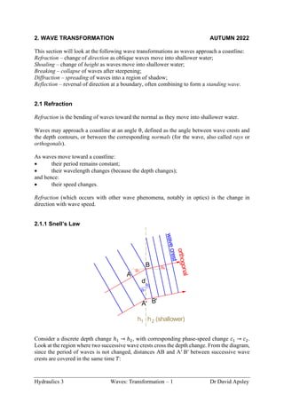
  • 1. Hydraulics 3 Waves: Transformation – 1 Dr David Apsley 2. WAVE TRANSFORMATION AUTUMN 2022 This section will look at the following wave transformations as waves approach a coastline: Refraction – change of direction as oblique waves move into shallower water; Shoaling – change of height as waves move into shallower water; Breaking – collapse of waves after steepening; Diffraction – spreading of waves into a region of shadow; Reflection – reversal of direction at a boundary, often combining to form a standing wave. 2.1 Refraction Refraction is the bending of waves toward the normal as they move into shallower water. Waves may approach a coastline at an angle θ, defined as the angle between wave crests and the depth contours, or between the corresponding normals (for the wave, also called rays or orthogonals). As waves move toward a coastline: • their period remains constant; • their wavelength changes (because the depth changes); and hence: • their speed changes. Refraction (which occurs with other wave phenomena, notably in optics) is the change in direction with wave speed. 2.1.1 Snell’s Law Consider a discrete depth change ℎ1 → ℎ2, with corresponding phase-speed change 𝑐1 → 𝑐2. Look at the region where two successive wave crests cross the depth change. From the diagram, since the period of waves is not changed, distances AB and A′ B′ between successive wave crests are covered in the same time 𝑇: B A A' B' h (shallower) 2 h1 1 2 1 w a v e c r e s t o r t h o g o n a l d 2
  • 2. Hydraulics 3 Waves: Transformation – 2 Dr David Apsley 𝑇 = distance speed = 𝑑 sin 𝜃1 𝑐1 = 𝑑 sin 𝜃2 𝑐2 Hence, sin 𝜃1 𝑐1 = sin 𝜃2 𝑐2 In reality, depth (and hence speed) change as waves approach the shore is gradual rather than sudden. However, it can still be imagined as a series of such small steps. Thus, refraction is governed by Snell’s law: sin 𝜃 𝑐 = constant or, in terms of wavenumber (since 𝑐 = 𝜔 𝑘 ⁄ , and frequency 𝜔 is unchanged): 𝑘 sin 𝜃 = constant or (𝑘 sin 𝜃)1 = (𝑘 sin 𝜃)2 Thus, wave direction changes approaching the coast may be determined from the change in celerity 𝑐 or wavenumber 𝑘 with depth. Since the depth, and hence speed, tend to zero at the coastline, obliquely- approaching waves eventually turn to meet the coast at 90º. (Waves never “miss” the beach!) 2.1.2 (Optional) Ray-Tracing Derivation of Snell’s Law This was taught in previous years, and hence appears in some exam papers. It is part of an impressively powerful, but considerably more mathematical approach to wave motion. The phase function (e.g. what goes inside the sine or cosine for a harmonic wave) of a disturbance travelling in the direction k = (𝑘𝑥, 𝑘𝑦, 0) is Ω = k•x − 𝜔𝑡 From this, k is the gradient of the phase; i.e. its components are the spatial partial derivatives: k = ∇Ω ≡ ( 𝜕Ω 𝜕𝑥 , 𝜕Ω 𝜕𝑦 , 𝜕Ω 𝜕𝑧 ) Since k is the gradient of a function it is irrotational (essentially because the second partial derivatives commute), so that k kx ky  x y coast
  • 3. Hydraulics 3 Waves: Transformation – 3 Dr David Apsley 𝜕𝑘𝑦 𝜕𝑥 − 𝜕𝑘𝑥 𝜕𝑦 = 0 Taking 𝑥 as toward the coast and 𝑦 as the along-shore direction parallel to the coast (strictly, parallel to the depth contours) quantities do not vary in the 𝑦 direction, so 𝜕𝑘𝑥 𝜕𝑦 ⁄ = 0. Hence, 𝜕𝑘𝑦 𝜕𝑥 = 0 or 𝑘𝑦(= 𝑘 sin 𝜃) is constant as before1 . Example. A straight coastline borders a uniformly-sloping sea bed. Regular waves are observed to cross the 8 m depth contour at an angle of 14° to the coastline-normal, with wavelength 45 m. Find: (a) the wave period; (b) the wavelength in deep water; (c) the direction in deep water. 1 There are many other ways of deriving Snell’s Law, including Fermat’s Principle of Least Time. This is worth looking up.
  • 4. Hydraulics 3 Waves: Transformation – 4 Dr David Apsley 2.2 Shoaling Shoaling is the change in height of waves as they move into shallower water. This occurs because of a change in group velocity (energy transmission velocity) as the depth decreases. If there is no bottom friction, no wave breaking and no reflection then the energy transmission shoreward must remain the same in all water depths. Wave energy (per unit surface area) and power (per unit length of crest) are given by 𝐸 = 1 2 𝜌𝑔𝐴2 = 1 8 𝜌𝑔𝐻2 𝑃 = 𝐸𝑐𝑔 where 𝐻 is the wave height and 𝑐𝑔 is the group velocity. For regular waves: 𝑐𝑔 = 𝑛𝑐 , where 𝑛 = 1 2 [1 + 2𝑘ℎ sinh 2𝑘ℎ ] , 𝑐 = 𝜔 𝑘 𝜔 and 𝑘 are related by the usual dispersion relation. Shoaling behaviour is determined on the basis that the shoreward component of energy transport is constant; i.e. 𝑃 cos 𝜃 = constant (An alternative approach assumes that the power between two orthogonals is constant. See the diagram for refraction in the previous section: 𝑃 × (length of crest) = 𝑃𝑑 cos 𝜃 for two orthogonals crossing a depth contour distance 𝑑 apart.) Since energy ∝ 𝐻2 the wave height approaching the shore satisfies 𝐻2 𝑐𝑔 cos 𝜃 = constant i.e. (𝐻2 𝑛𝑐 cos 𝜃)1 = (𝐻2 𝑛𝑐 cos 𝜃)2 If subscript 1 denotes reference (often deep-water) conditions, then at location 2: 𝐻2 = 𝐻1 ( cos 𝜃1 cos 𝜃2 ) 1 2 ⁄ ⏟ refraction coefficient 𝐾𝑅 ( (𝑛𝑐)1 (𝑛𝑐)2 ) 1 2 ⁄ ⏟ shoaling coefficient 𝐾𝑠 coast  P P cos
  • 5. Hydraulics 3 Waves: Transformation – 5 Dr David Apsley Note that as the wave moves into shallower water: • the wavelength decreases and an oblique wave will turn toward the normal; • at intermediate depths the height may actually increase or decrease depending on group velocity and refraction; however, in sufficiently shallow water, cos 𝜃 → 1, 𝑛 → 1 and 𝑐~√𝑔ℎ, so eventually wave height must increase; the resulting steepening of the wave ultimately leads to wave breaking (see later). Example. Exam 2016 (part) Waves propagate towards a long straight coastline that has a very gradual bed slope normal to the coast. In water depth of 20 m, regular waves propagate at heading 𝜃 = 40° relative to the bed slope. (a) Sketch the shape of a wave ray from the 20 m depth contour to the 5 m depth contour for a wave that is of deep-water type in both depths and, separately, for a wave that is of shallow water type in both depths. Calculations are not required. (b) For a wave with period 𝑇 = 8 s and height 1.2 m at 20 m depth, calculate the wave heading and wave height at the 5 m depth contour.
  • 6. Hydraulics 3 Waves: Transformation – 6 Dr David Apsley 2.3 Breaking As waves move into shallow water, shoaling causes wavelength to decrease, but wave height ultimately to increase; i.e. the wave steepens. According to linear theory, 𝐻 would become unbounded, but, in reality, linear theory breaks down, waves become unstable and break, dissipating their energy in turbulence and subsequently running up the beach at much reduced depth accompanied by foam (the post-breaking or swash zone). Because wave loading on structures depends significantly on wave height, design and siting of nearshore structures requires knowledge of the breaking point. 2.3.1 Breaking Criteria Wave breaking depends on the ratio of wave height (𝐻) to wavelength (𝐿) and/or depth (ℎ), and on the slope of the beach (𝑚). Miche Criterion (Steepness, or Height-to-Wavelength Ratio) An early criterion was that of Miche (1944): ( 𝐻 𝐿 ) 𝑏 = 0.14 tanh(𝑘ℎ)𝑏 where subscript 𝑏 denotes breaking conditions. Note that wavelength 𝐿 and the corresponding wavenumber 𝑘 = 2π/𝐿 are the local conditions, i.e. at the breaking point. A useful interpretation is that waves break when fluid particles moving at the wave crest speed 𝑢max begin to catch up with the wave speed 𝑐: 𝑢max 𝑐 = (𝐴𝑔𝑘 𝜔 ⁄ ) (ω 𝑘 ⁄ ) = 𝐴𝑔𝑘2 𝜔2 = 𝐴𝑘 tanh 𝑘ℎ = π𝐻/𝐿 tanh 𝑘ℎ Thus, 𝑢max/𝑐 reaches some critical value when 𝐻 𝐿 = constant × tanh(𝑘ℎ) with the constant being determined empirically. In deep water (tanh 𝑘ℎ → 1) the Miche criterion yields a critical steepness ( 𝐻 𝐿 ) 𝑏 = 0.14 , or about 1 7 In shallow water (tanh 𝑘ℎ ~𝑘ℎ) this gives, with 𝑘 = 2π/𝐿, ( 𝐻 𝐿 ) 𝑏 = 0.14 × 2πℎ 𝐿 or a breaker depth index (see below) 𝛾𝑏 = ( 𝐻 ℎ ) 𝑏 = 0.88
  • 7. Hydraulics 3 Waves: Transformation – 7 Dr David Apsley This is slightly on the high side. Breaker Height Index The breaker height index is Ω𝑏 = 𝐻𝑏 𝐻0 ( wave height at breaking deep-water height ) The deep-water wave height 𝐻0 can be determined from height at any known location via the shoaling equation (see example below). A commonly-used correlation is Ω𝑏 = 0.56 ( 𝐻0 𝐿0 ) −1 5 ⁄ where deep-water wave height 𝐻0 is established from shoaling and the deep-water wavelength 𝐿0 is calculated from the wave period: 𝐿0 = 𝑔𝑇2 /2π. Breaker Depth Index The breaker depth index is 𝛾𝑏 = ( 𝐻 ℎ ) 𝑏 ( wave height at breaking water depth at breaking ) McCowan (1894) gave a critical value 𝛾𝑏 = 0.78, which is still widely used for shallow-water breaking on mild slopes. However, use of a constant value fails to recognise the role of beach slope, m. A reanalysis of data by Weggel (1972) produced the following empirical formulae for the critical breaker depth index: 𝛾𝑏 = 𝑏 − 𝑎 𝐻𝑏 𝑔𝑇2 = 𝑏 − 𝑎 𝐻𝑏 2π𝐿0 where 𝑎 = 43.8(1 − 𝑒−19𝑚), 𝑏 = 1.56 1 + 𝑒−19.5𝑚 Again, this bases the measure of steepness 𝐻𝑏/𝐿0 on the deep-water wavelength 𝐿0. Note that this gives 𝛾𝑏 = 0.78 when the beach slope 𝑚 → 0, consistent with the earlier approximation. 2.3.2 Types of Breakers The type of breaker which ensues depends on the beach slope m compared with the wave steepness 𝐻/𝐿0 (again based on the deep-water wavelength) and has been found to correlate well with the Irribarren number (aka surf-similarity parameter): 𝜉0 = 𝑚 √𝐻0/𝐿0 or 𝜉𝑏 = 𝑚 √𝐻𝑏/𝐿0 ( beach slope √wave steepness )
  • 8. Hydraulics 3 Waves: Transformation – 8 Dr David Apsley (Note the two possibilities, depending on whether the breaking height 𝐻𝑏 or deep-water height 𝐻0 is used.) Then: 𝜉0 < 0.5 spilling breakers 0.5 < 𝜉0 < 3.3 plunging breakers 3.3 < 𝜉0 surging or collapsing breakers If 𝜉𝑏 is used instead then the limiting numbers are 0.4 and 2.0 (Battjes, 1974). Spilling breakers occur for steep waves or mildly-sloping beaches (typically less than 1 in 100). Foam spills down the front of the crest (“white horses”). Gentle, slowly-breaking waves. Plunging breakers occur on moderately steep beaches. The steepening wave front curls over the preceding trough and crashes down into it. Sudden, violent, dissipative breaking. Collapsing breakers occur for very long waves or very steep beaches. Crest never fully rolls over but the steep front face collapses from the bottom. Surging breakers occur for long-period, low-steepness waves on steep beaches. The wave may not break, but forms a front, with extensive run-up on the beach. Lack of dissipation means these are quite reflective. Spilling Plunging Collapsing Surging
  • 9. Hydraulics 3 Waves: Transformation – 9 Dr David Apsley Example. Waves propagate towards a long straight coastline that has a constant bed slope of 1 in 100. Consider the x-axis to be normal to the coastline and the y-axis parallel to the coastline. Waves propagate at an angle θ to the x-axis. (a) A wave with period 7 s and height 1.2 m crosses the 36 m depth contour at angle 𝜃 = 22°. (i) Determine the direction, height and power per metre width of wave crest at the 4 m depth contour. (ii) Explain how height changes between these depths. (b) A wave with period 7 s and height 1.0 m crosses the 4 m depth contour at angle 𝜃 = 0°. Determine the breaking wave height and breaking depth from their corresponding indices and identify the type of breaker expected. (c) Further along the coast, waves propagate over the outflow of a river. In water depth of 14 m, measurements indicate a period of 7 s and depth-averaged flow velocity of 0.8 m s–1 against the wave direction. Determine the wavelength. Example. (Exam 2017, part) Waves propagate towards a straight shoreline. The wave heading is equal to the angle formed between wave crests and the bed contours. The bed slope is less than 1 in 100. Waves are measured in 30 m depth and wave conditions at 6 m depth are required to inform design of nearshore structures. Regular waves are measured with period of 7 s and height of 3 m. (a) Determine the water depth in which waves with this period can be considered as deep- water waves. (b) For 30 m depth, determine the breaking height by the Miche criterion and briefly describe this type of breaking wave. (c) If the heading is zero degrees, calculate wave height in 6 m depth. State your assumptions. (d) If the heading of the measured conditions is 30°, calculate the wave heading and height in 6 m depth. Hence calculate the change of wave power per unit width of wave crest (kW m–1 ) between the two depths.
  • 10. Hydraulics 3 Waves: Transformation – 10 Dr David Apsley 2.4 Diffraction When an obstacle, for example a harbour breakwater or offshore structure, impedes the passage of a wave it creates a region of geometric shadow. Since the water waves still cause oscillations in the “illuminated zone” (note the analogy with light waves!) disturbances must propagate into the region of shadow to avoid discontinuities in the water surface. Diffraction is the spreading of waves into a region of geometric shadow. 2.4.1 Diffraction Coefficients Diffraction behaviour is difficult to calculate (see the optional summary at the end of this section if you are interested) and data is usually presented either as charts (e.g. Shore Protection Manual (1984), or USACE Coastal Engineering Manual), tables, or computer software in terms of diffraction coefficients: 𝐾𝐷(x) = 𝐻(x) 𝐻0 the ratio of wave heights (or amplitudes) at a particular point to those in an incident plane wave. wave reflection illuminated zone geometric shadow breakwater
  • 11. Hydraulics 3 Waves: Transformation – 11 Dr David Apsley Semi-infinite plane breakwater; 90° wave incidence Note that the wave height along the line behind the breakwater tip is exactly half that in the incident wave. This continues (as an approximation) for other angles of incidence. Breakwater with a 2L gap
  • 12. Hydraulics 3 Waves: Transformation – 12 Dr David Apsley Offshore finite breakwater; length 10L 2.4.2 (Optional) Calculation of Diffraction Coefficients For the interested, diffraction patterns are the result of solving for a complex velocity potential of the form 𝜙 = cosh 𝑘(ℎ + 𝑧) cosh 𝑘ℎ 𝐹(𝑥, 𝑦)𝑒−i𝜔𝑡 (The actual physical solution would just be the real part of this complex number). For an incident plane wave with wavenumber vector k and unit amplitude, 𝜙 will satisfy the Laplace equation if 𝐹 satisfies a Helmholtz equation of the form 𝜕2 𝐹 𝜕𝑥2 + 𝜕2 𝐹 𝜕𝑦2 = −𝑘2 𝐹 with boundary conditions 𝐹~eik●x at infinity 𝜕𝐹 𝜕𝑛 = 0 on solid boundaries The first boundary condition defines the incident unit-amplitude plane wave and the latter the kinematic condition of no velocity through the boundary. As a complex number, the amplitude of 𝐹 gives the diffraction coefficient (ratio of wave height at a point to that in the incident wave), whilst its phase can be used to find the wave crests.
  • 13. Hydraulics 3 Waves: Transformation – 13 Dr David Apsley Penney and Price (1952)2 give the exact solution for oblique incidence on a semi-infinite plane breakwater (based on a classical solution for light waves by Sommerfeld, 1896) and approximate, but fairly accurate, solutions for finite-length breakwaters and breakwater gaps. The diagrams in these notes have been plotted from the solutions in that paper. Further chart-based solutions are available from the Shore Protection Manual3 or the US Army Corps of Engineers Coastal Engineering Manual4 . . Example. A harbour is to be protected by an L-shaped breakwater as sketched. Determine the length 𝑋 of the outer arm necessary for the wave height at point P to be 0.3 m when incident waves have a height of 3 m and a period of 5 s. The depth is everywhere uniform at 5 m. The diffraction diagram for the appropriate approach angle is shown. Neglect reflections within the harbour. 2 Penney, W.G. and Price, A.T., 1952, The diffraction theory of sea waves and the shelter afforded by breakwaters, Phil. Trans. Roy. Soc. London, Ser A, 244, pp. 236-253. 3 Downloadable from, e.g., http://resolver.tudelft.nl/uuid:98791127-e7ae-40a1-b850-67d575fa1289 4 Downloadable from, e.g., Chapter 7 in: https://www.publications.usace.army.mil/Portals/76/Publications/EngineerManuals/EM_1110-2-1100_Part- 02.pdf P 90 m 90 m X incident wave crests 75o
  • 14. Hydraulics 3 Waves: Transformation – 14 Dr David Apsley 2.5 Reflection 2.5.1 Combining Incident and Reflected Waves When a wave reaches a rigid impermeable vertical wall it is reflected, with boundary condition 𝑢 = 0 at the wall Consider the superposition of two progressive waves with similar frequencies and wavenumbers, but travelling in opposite directions: an incoming one (coming from the right) and an outgoing one. For example, the water surface elevation: 𝜂 = 𝐴 cos(𝑘𝑥 − 𝜔𝑡) + 𝐴 cos(−𝑘𝑥 − 𝜔𝑡) = 𝐴[cos(𝑘𝑥 − 𝜔𝑡) + cos(𝑘𝑥 + 𝜔𝑡)] = 2𝐴 cos 𝑘𝑥 cos 𝜔𝑡 This produces a standing wave (at any point in space it oscillates harmonically in time) with double the amplitude, with nodes (points of zero displacement) at 𝑘𝑥 = π 2 ⁄ , 3π 2 ⁄ , 5π 2 ⁄ , … corresponding to 1/4, 3/4, 5/4 … wavelengths back from the reflective wall. The corresponding velocity superposition gives 𝑢 = 𝐴𝑔𝑘 𝜔 cosh 𝑘(ℎ + 𝑧) cosh 𝑘ℎ cos(𝑘𝑥 − 𝜔𝑡) + 𝐴𝑔(−𝑘) 𝜔 cosh[(−𝑘)(ℎ + 𝑧)] cosh[(−𝑘)ℎ] cos(−𝑘𝑥 − 𝜔𝑡) = 𝐴𝑔𝑘 𝜔 cosh 𝑘(ℎ + 𝑧) cosh 𝑘ℎ [cos(𝑘𝑥 − 𝜔𝑡) − cos(𝑘𝑥 + 𝜔𝑡)] = 2𝐴𝑔𝑘 𝜔 cosh 𝑘(ℎ + 𝑧) cosh 𝑘ℎ sin 𝑘𝑥 sin 𝜔𝑡 Again, this corresponds to a standing wave. The points of zero horizontal velocity are 𝑘𝑥 = 𝑛π and hence this could describe reflection at any of these points. Hence: • (Complete) reflection can be represented by the superposition of two equal and opposite progressive waves to form a standing wave. • The standing wave has the same wavelength and frequency but twice the amplitude. • There are nodes (positions of zero surface displacement η) separated by distance π 𝑘 ⁄ or 𝐿 2 ⁄ (i.e. half a wavelength), with velocity nodes half way between them. • The point of reflection corresponds to a point of zero velocity and double-amplitude displacement. This is important when we consider wave forces on structures. node
  • 15. Hydraulics 3 Waves: Transformation – 15 Dr David Apsley 2.5.2 Seiching (Basin Oscillations) Just like musical instruments, standing waves may occur in enclosed basins (reflection from both ends) as a resonance condition if the wind-speed and basin dimensions are favourable. The first few modal shapes are illustrated below. The basin length is a whole number of half-wavelengths: 𝐵 = 𝑛𝑠( 1 2 𝐿) or 𝐿 = 2𝐵 𝑛𝑠 The enclosure means that these are typically shallow-water waves with speed 𝐿 𝑇 = √𝑔ℎ with seiching period (Merian formula): 𝑇 = 2𝐵 𝑛𝑠√𝑔ℎ Only the fundamental mode (𝑛𝑠 = 1) is usually established. Example. Lake Baikal in Siberia contains about one fifth of the world’s fresh-water resources. It is 636 km long, with an average depth of 744 m. Find the fundamental period for seiching. Fundamental (mode 1) Mode 2 Mode 3 B