SQL Database Design For Developers at php[tek] 2024
Lte channel
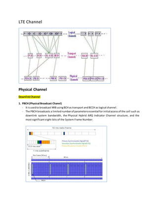
1. LTE Channel
Physical Channel
DownlinkChannel
1. PBCH (Physical Broadcast Chanel)
- It isusedto broadcast MIB usingBCH as transport andBCCH as logical channel.
- The PBCH broadcasts a limitednumberof parametersessential for initialaccessof the cell such as
downlink system bandwidth, the Physical Hybrid ARQ Indicator Channel structure, and the
most significant eight-bits of the System Frame Number.
2. As showninthe figure,PBCHisdownlinkonly channel. It occupies 72 subcarriers belong to first 4
OFDMA symbols of second slot of every 10ms radio frame. Pls. note that reference signal
resource elements(REs) are excludedfromthe PBCHallocation.Hence PBCH will occupy about (72
x 4) - 48 = 240 REs. As PBCH uses QPSK modulation, it leads to about 480bits per 240 REs.
- PBCH is downlink only channel.
- It occupies 72 subcarriers belong to first 4 OFDMA symbols of second slot of every 10ms radio
frame. Pls. note that reference signal resource elements(REs) are excluded from the PBCH
allocation. Hence PBCH will occupy about (72 x 4) - 48 = 240 REs. As PBCH uses QPSK modulation,
it leads to about 480bits per 240 REs.
- These parametersare carriedin - a Master InformationBlock(MIB) (14 bitslong).Thisinformation
is required to decode other physical channels.
- The PBCH is designed to be detectable without prior knowledge of system bandwidth and to be
accessible at the cell edge also.
- The MIB iscoded at a very low coding rate and mapped to the 72 center sub-carriers (6 RBs, each
RBs = 12 sub carriers, so 6x12 = 72 subcarriers) of the OFDMstructure.
- PBCH transmission is spread over four 10 ms frames (over subframe 0) to span a 40 ms period.
- Each subframe isself decodable whichreduceslatencyandUE batterydrain in case of good signal
quality,otherwise,the UE wouldsoft-combinemultiple transmissions until the PBCH is decoded.
- After the successful execution of the cell-search procedure, UE decodes the PBCH (MIB/SIBs).
OverheadGeneratedbyLTE PBCH channel
LTE PBCH represents an overhead which reduces the number of REs available for user plane data.
Overheadislessforlargerbandwidthand more forextendedCP(cyclicprefix).Asmentionedinthe table
below LTE PBCH overhead is in-significant for larger channel BW and significant for small channel BW.
3. 2. Physical Control Format Indicator Channel (PCFICH)
The Physical Control FormatIndicatorChannel (PCFICH) isusedat the startingof each 1ms subframe.
It providesinformationaboutnumber of symbolsusedforPDCCHtransmission.The signalling values
for PCFICH depends upon channel bandwidth. The same is mentioned in the following table-1 for
different LTE channel bandwidths.
As mentioned 1.4MHz requires more time domain symbols compare to other channel bandwidths
due to less carriers in frequency domain. Signalling value depends on eNodeB RRM(Radio
Resource Management). It depends on number of active connections. Hence PDCCH signalling
increases as per increase in number of active connections.
As shown in the figure, LTE PCFICH channel occupies 16 REs(Resource Elements) in first OFDMA
symbol of each1ms frame. PCFICH uses QPSK modulation and hence 16 REs will occupy 32 bits. This
16REs are divided into 4 quadruplets. The position of which in first OFDMA symbol depends on
Channel BW and Physical layer cell identity.
As mentioned each quadruplet is mapped to REG(Resource Element Group) with subcarrier index
k = k' and is as per following equation.
k'= (Nsc per RB /2) * (NCellID mod2 NDL-RB )
NcellID = Physical Cell id
NDLRB = Number of resource blocks per bandwidth
NRBSC = Number of frequency carriers per Resource block
4. Lets suppose
Physical Cell id =20
Bandwidth =10Mhz (NDLRB =50)
Then accordingto 3GPP Formula
k_Bar = (12/2).(20 mod 2*50) =6*20 = 120
Then the four PCFICHmappingvalues are below
120
120 + (50/2)*(12/2) =270
120 + 2*(50/2)*(12/2) =420
120 + 3*(50/2)*(12/2) =570
The rest of three quadruplets are mapped to REGs spaces at intervals of (NDL-RB/2) * (Nsc per RB /2)
from the first quadruplet and each other. This way LTE PCFICH channel information is spread across
entire subframe as shown.
The PCFICH carriesCFI(Control FormatIndicator) whichhasavalue rangingfrom 1 to 3. This CFI is coded
to occupy complete PCFICH capacity of 32 bits.
Actual value = signalled value + 1 (for 1.4 MHz BW)
Actual value = signalled value (for all the channel BWs)
Overheaddue to LTE PCFICHchannel
Like LTE PBCH, PCFICH also introduces overhead which reduces number of resource elements needed
for user plane data. As mentioned in table-2 overhead is less for higher bandwidth and more for
extended CP.
3. Physical Downlink Control Channel (PDCCH)
It is used to carry DCI (Downlink Control Information). We get the information about number
of OFDMA symbols used by PDCCH after decoding PCFICH. The symbols are always at the start of
each subframe.
5. The REs(Resource Elements) allocated to PDCCH are grouped into group of 4 REs referred as
quadruplets. RE quadruplets are grouped into CCE ( Control Channel Elements). There are 9
quadruplets in one CCE. Hence 36 REs per CCE. PDCCH uses QPSK which provides CCE capacity of
about 72 bits.
There are total 4 PDCCH formats as described in document 3GPP TS 36.211. The same is mentioned
in table-1 below :
The PDCCH format is used as per required size of DCI. The DCI bits have 16 bit CRC attached prior to
rate-1/3 channel coding&rate matchingmodules. The table-2 below mentions coding rate for each
DCI and PDCCH format. coding rate = number of DCI bits after CRC attachment/Capacity of PDCCH.
6. The number of CCE depends on channel BW and number of OFDMA symbols allocated for PDCCH.
The table represents the same assuming no quadruplets have been allocated to PHICH and 4x4
MIMO is not used.
- This channel is used to inform the UE about the resource allocation of PCH and DL-SCH
- indicating the modulation, coding and hybrid-ARQ information related to DL-SCH
- Generally, a maximum of three or four OFDMsymbols can be used for PDCCH
- The information carried on PDCCH is referred to as downlink control information (DCI)
- Uses QPSK modulation
4. Physical Downlink Share Channel (PDSCH)
The PDSCH channel is the main data bearing channel which is allocated to users on a dynamic and
opportunisticbasis.The PDCHisalsoused to transmit broadcast information not transmitted on the
PBCH which include SystemInformationBlocks(SIB) andpaging&RRC signalling messages. PDSCH is
also used to transfer application data.
- Paging messages-These are broadcast using PDSCH channel. LTE UE in RRC IDLE mode
monitor PDCCH for paging indications. Based on trigeer it will decode the paging message
carried in PDSCH RBs.
7. - Downlink RRC Signalling messages-These are carried by PDSCH. Signalling Radio
Bearers(SRB) will use PDSCH. Every connection usually will have its own set of SRB.
For LTE PDSCH channel uses QPSK, 16QAM, 64QAM modulation types. LTE eNodeB selects suitable
modulationtype based on adaptation algorithm. This further depends on radio channel condition and
buffercapacity.QPSKismostrobustscheme and hence it is used for transmission of SIB and Paging. As
the name suggests PDSCH is a shared channel and hence its RBs are shared among all the
active connections.
5. Physical Multicast Channel (PMCH)
This channel defines the physical layer structure to carry Multimedia Broadcast and Multicast
Services (MBMS). This control channel occupy the first 1, 2, or 3 OFDM symbols in a subframe
extending over the entire system bandwidth.
For PMCH channel QPSK, 16QAM, 64QAM modulations are used. It carries MCH. Multicast Channel
(MCH) characterised by:
- Requirement to be broadcast in the entire coverage area of the cell
- Support for MBSFN combining of MBMS transmission on multiple cells
- Support for semi-static resource allocation e.g. with a time frame of a long cyclic prefix.
In Downlink, MTCH logical channel can be mapped to DL-SCH and MCH transport channels.
6. Physical Hybrid ARQ Indicator Channel (PHICH)
The PHICH is usedtocarry positive ornegative acknowledgementsfor uplink data transferred on the
PUSCH. They are referred as ACK/NACK. Each connection can carry a max. of 1 TB(Transport Block)
persubframe onPUSCH. Hence a maximumof 1 PHICHACK per subframe per connection is needed.
8. A PHICH ASK is identified by two parameters :
- PHICH Group
- PHICH Orthogonal sequence index within PHICH group
As showninthe figure,three REGsthat supporta PHICH groupare evenly distributed across LTE system
BW. This provides frequency diversity. As mentioned here PCFICH always appear and will occupy first
symbol of each subframe. PCFICH occupy 4REGs irrespective of channel bandwidth.
The number of PHICH groups is a function of downlink channel bandwidth and PHICH group scaling
factor. Both the downlink channel BW and PHICH group scaling factor are tranmitted within MIB
and carried by LTE PBCH channel. The table-1 below mentions number of PHICH groups for various
scaling factor,CPs and channel BWs.
The no. of PHICH groupsbecome double whenusingextendedCP because no. of orthogonal sequences
for each group became halved.
- Normal CP has 8 orthogonal sequences per PHICH group
- Extended CP has 4 orthogonal sequences per PHICH group
9. A UE selects its PHICH group and orthogonal sequence index as per following equation:
PHICH Group = ( Ilowest + nDMRS ) *mod( N group )
PHICH Sequence Index = ( [Ilowest / N group] + nDMRS ) * mod(Nseq)
Where ;
Ilowest = Lowest physical RB index allocated to slot-1 of PUSCH
nDMRS = Demodulation RS cyclic shift signalled within LTE DCI-0
N group = No. of PHICH groups
Nseq = No. of orthogonal sequences per PHICH group (Normal CP: 8 and Extended CP:4)
Each PHICH ACK ismodulated using BPSK modulation scheme and occupies :
- 12 REs when using normal CP
- 6 REs when using extended CP
PHICH ACKbelongsto same group will occupy same set of REs and are differentiated using orthogonal
sequences. In extended CP case, PHICH groups are paired and each pair of groups occupy 12 REs.
The Set of 12 REs allocated to each PHICH group is divided into three quadruplets. MIB on PBCH
indicates whether PHICH uses normal CP or extended CP. A normal CP means PHICH uses first OFDMA
symbol belongs to a subframe. A extended CP means PHICH uses first 3 OFDMA symbols belong to a
subframe.
UplinkChannel
1. Physical UplinkControl Channel (PUCCH)
This LTE channel is used to carry UCI(Uplink Control Information). UCI can also be transported using
PUSCH channel. An LTE UE can never transmits both PUCCH and PUSCH during the same subframe.
- If UE has application data OR RRC signalling then UCI is carried over PUSCH
- If UE does not have any application data OR RRC signalling then UCI is carried over PUCCH
Thisis a stand-alone uplinkphysical channel.ThisPUCCHcontrol signalingchannelcomprisesfollowing :
- HARQ ACK/NACK
- CQI-channel quality indicators
- MIMO feedback - RI(Rank Indicator),PMI(Precoding Matrix Indicator)
- Scheduling requests for uplink transmission
- BPSK or QPSK used for PUCCH modulation
10. PUCCH consistsof 1 RB/transmissionatone endof the system bandwidth which is followed by another
RB in the followingslot(at oppositeendof the channel spectrum).Thismakesuse of frequency diversity
with 2dB estimated gain. A PUCCH Control Region comprises every two such RBs.
The standard specifies 6 LTE PUCCH formats as mentioned in the table-2 below. As mentioned PUCCH
format 2a and 2b are not applicable for extended CP.
11. The LTE PUCCH channel isallocated2 RBs at the edgesof channel BW. Each PUCCH transmission occupy
1 RB on each side of the channel bandwidth. These two RBs are distributed across two time slots. RB
numberingforPUCCHstarts on outside edgesandincreases inwards.PUCCHisallocatedRBsatthe edge
of channel BW to avoid fragmenting RBs available to PUSCH.
2. Physical UplinkShared Channel (PUSCH)
This channel is used to carry RRC signalling messages, UCI (uplink Control Information) and
application data. Uplink RRC messages are carried using PUSCH. SRB use PUSCH and each and every
connection will have its unique SRB.
- LTE PUSCH channel contain user information data.
- The PUSCH carriesbothuserdata as well ascontrol signal data. Control information carried
can be MIMO related parameters and transport format indicators.
- The control data informationismultiplexedwiththe userinformation before DFT spreading
module in the uplink SC-FDMA physical layer.
- PUSCH supports QPSK,16QAM and 64QAM(optional). The LTE eNodeB selects suitable
modulation based on adaptation algorithm.
UCI is transmitted using PUSCH instead of PUCCH when there is RRC and application data to be
transferred at the same time instant.
12. Modulation type is conveyed to UE using PDCCH DCI format-0. This CI also signals RB allocation and
TB size. LTE PUSCH channel uses QPSK when TTI bundling is enabled. If eNodeB directs UE to use
64QAM, but if UE does not support it then 16QAMmodulation type is selected.
3. Physical Random AccessChannel
Thispage on LTE PRACHdescribesLTE Physical RandomAccess Channel(PRACH).It mentions links for
WCDMA PRACH and GSM RACH channel basics.
This channel is used to carry random access preambles used for initiation of random access
procedure. The basic structure is mentioned in the figure. As shown a random access preamble
includes a CP, a sequence and a guard time.
This carries the random access preamble. The RACH transport channel is mapped to this.
- Carries the random access preamble a UE sends to access the network
- It consists of 72 sub-carriers in the frequency domain
- There are 4 different RA(random access) preamble formats defined in LTE FDD
specifications.The same have beenmentionedinthe table-1 below. It consists of different
preamble and CP duration to accommodate different cell sizes.
The preamble format to be used in a specific cell is informed to the UE using PRACH configuration
index.ThisisbroadcastedinSIB-2.PRACHconfigurationindex alsoindicatesSFN andsubframes. This
gives the exact position of random access preamble. Table-2 beloe mentions LTE PRACH channel
configuration index, preamble format, allowed SFN and allowed subframes.
The preamble uses subcarrier spacing of 1.25KHz instead of 15KHz. The random access preamble
occupies 1,2 or 3 subframes in the time domain(1,2,3ms) and 839 subcarriers in frequency
domain(1.05MHz). There will be 15KHz guard band on both the sides and hence it uses total of
1.08MHz (equal to 6 RBs). The position of LTE random access preamble is defined by PRACH
frequency offset parameter carried in SIB-2.
13. There is a max. of 1 random access preamble in a subframe but more than one UEs can use it.
Multiple UEsusingsame preamble resource allocationsare differentiated by their unique preamble
sequences.
As mentioned in table-2 max. of 64 preamble sequences are divided into group-A and group-B. LTE
UE selectsthe sequence fromthese two groupsbased on size of uplink packet and radio conditions.
Thishelps eNodeBtocalculate PUSCHresourcesneededforUE uplinktransfer. SequencesinGroup-A
are usedforsmallersize packetsorlargersize packetsinpoorradio conditions.SequencesinGroup-B
are used for larger size packets in good radio conditions.
Transport Channel
The LTE transport channels vary between the uplink and the downlink as each has different
requirements and operates in a different manner. Physical layer transport channels offer information
transfer to medium access control (MAC) and higher layers.
Downlink Channel
- Broadcast Channel (BCH)
The LTE transport channel maps to Broadcast Control Channel (BCCH)
- Downlink Shared Channel (DL-SCH)
This transport channel is the main channel for downlink data transfer. It is used by many logical
channels.
- Paging Channel (PCH)
To convey the PCCH
14. - Multicast Channel (MCH)
This transport channel is used to transmit MCCH information to set up multicast transmissions.
Uplink Channel
- Uplink Shared Channel (UL-SCH)
This transport channel is the main channel for uplink data transfer. It is used by many logical
channels.
- Random Access Channel (RACH)
This is used for random access requirements.
Logical Channel
The logical channels cover the data carried over the radio interface. The Service Access Point,
SAP between MAC sublayer and the RLC sublayer provides the logical channel.
Control Channel : these LTE control channels carry the control plane information:
- Broadcast Control Channel (BCCH)
This control channel provides system information to all mobile terminals connected to the
eNodeB.
- Paging Control Channel (PCCH)
This control channel is used for paging information when searching a unit on a network.
- Common Control Channel (CCCH)
This channel is used for random access information, e.g. for actions including setting up a
connection.
- Multicast Control Channel (MCH)
This control channel is used for Information needed for multicast reception.
- Dedicated Control Channel
This control channel is used for carrying user-specific control information, e.g. for controlling
actions including power control, handover, etc
Traffic Channel : These LTE traffic channels carry the user-plane data:
- Dedicated Traffic Channel (DTCH)
This traffic channel is used for the transmission of user data.
- Multicast Traffic Channel (MTCH)
This channel is used for the transmission of multicast data.