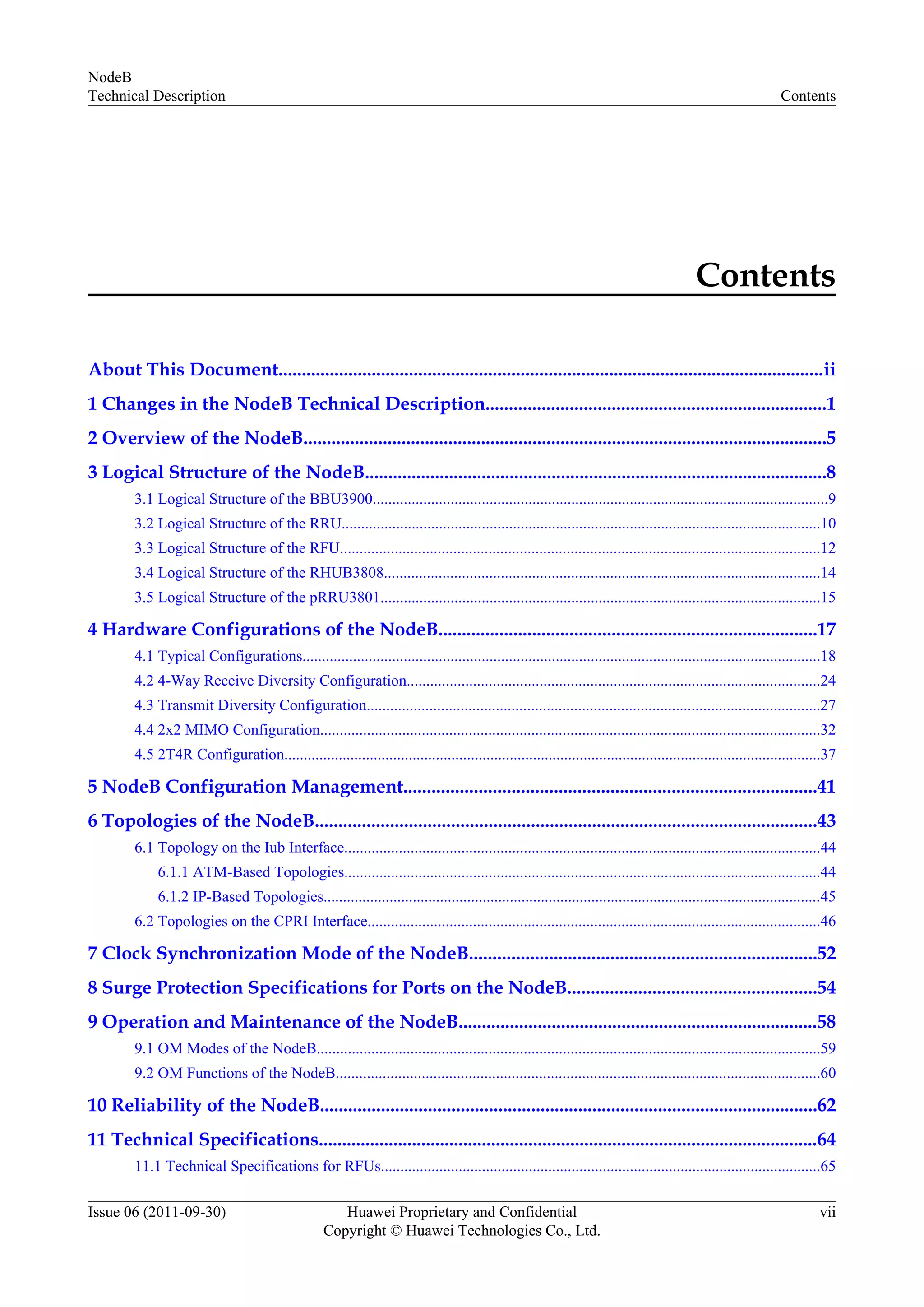
This document provides a technical description of the NodeB, including its functions, logical structure, hardware configurations, topologies, clock synchronization modes, operation and maintenance, and reliability. It describes the typical, 4-way receive diversity, transmit diversity, 2x2 MIMO, and 2T4R hardware configurations. It also covers the logical structures of components like the BBU3900, RRU, RFU, RHUB3808, and pRRU3801. The document discusses NodeB configuration management, topologies on the Iub and CPRI interfaces, clock synchronization modes, surge protection specifications, operation and maintenance, and reliability. It provides technical specifications for various RFU and RRU models.
Document provides technical details on NodeB, copyright info and audience details.
Describes structure, intended audience, and contents of NodeB technical document.
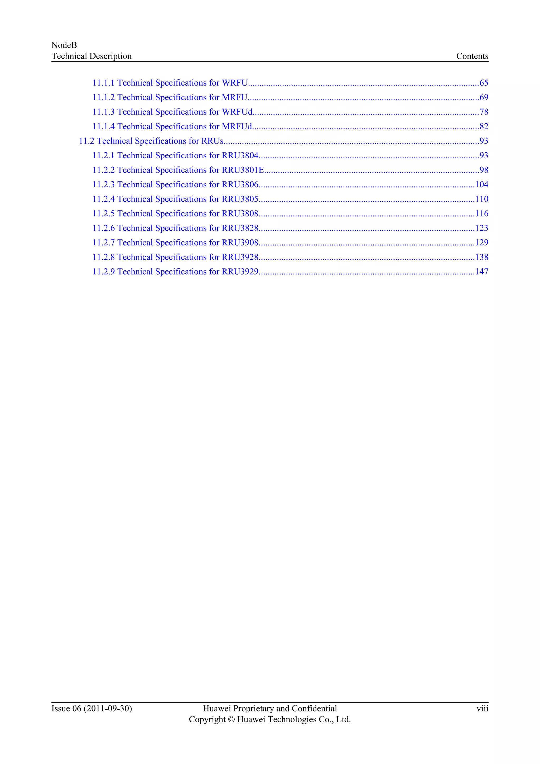
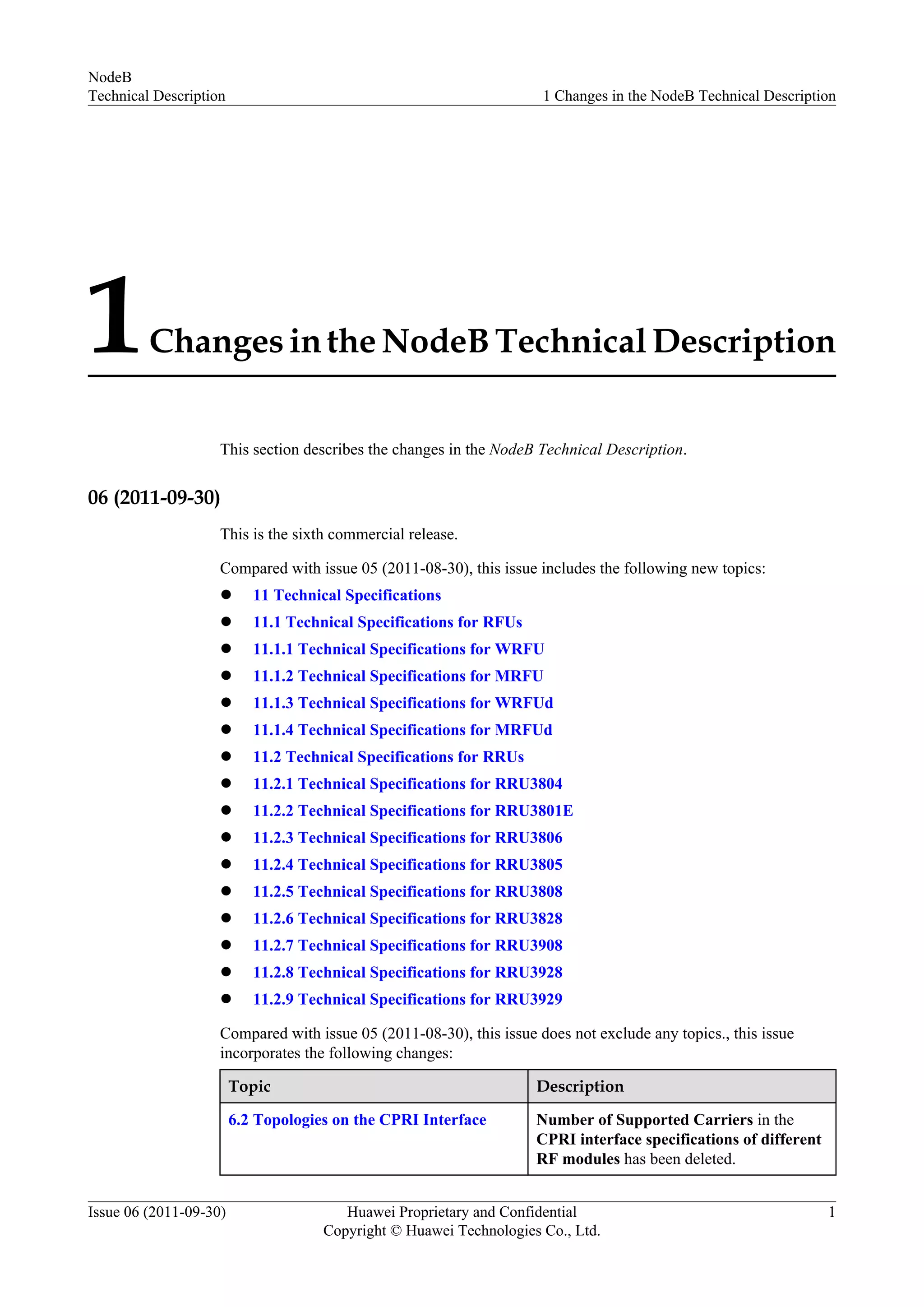
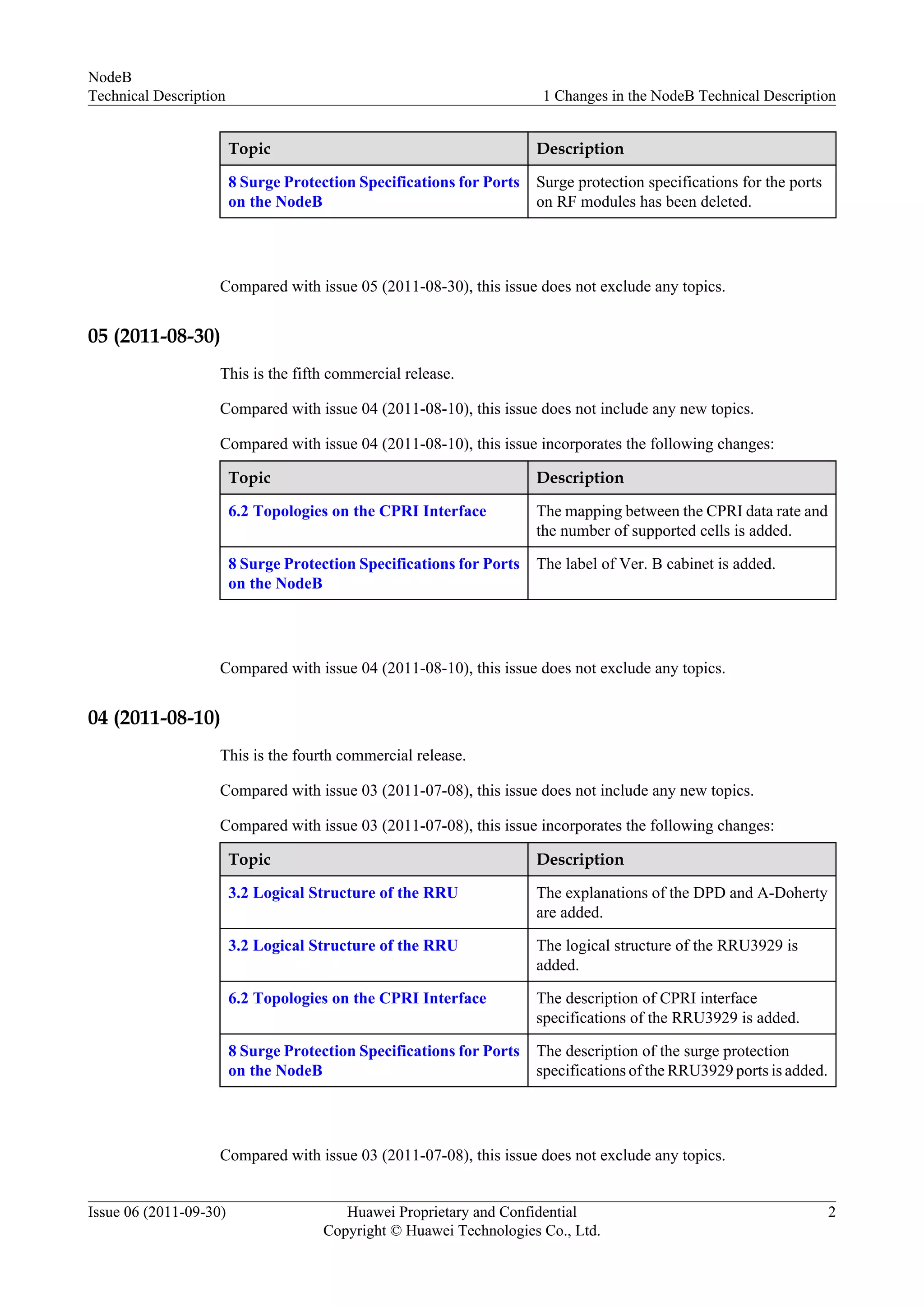
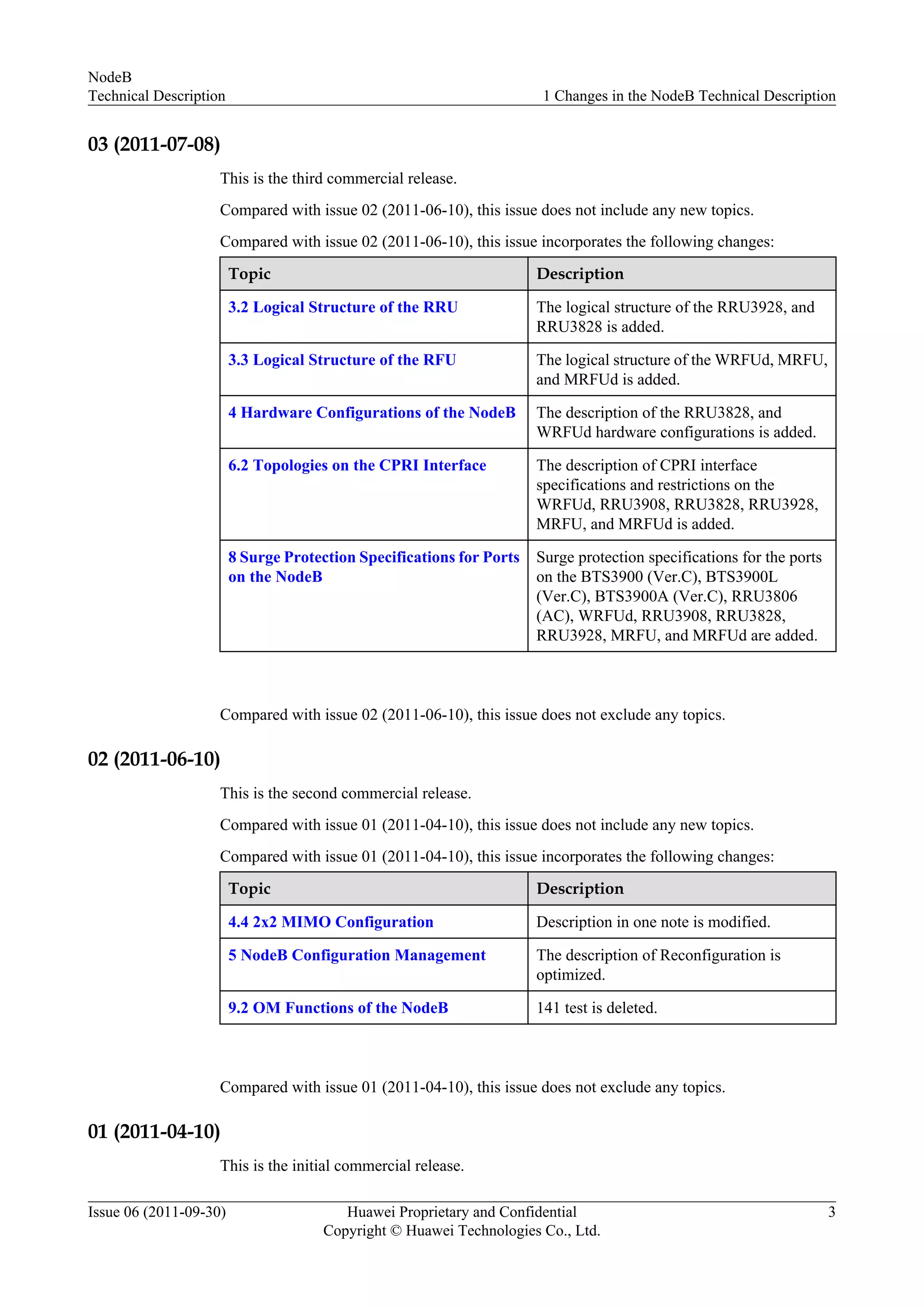
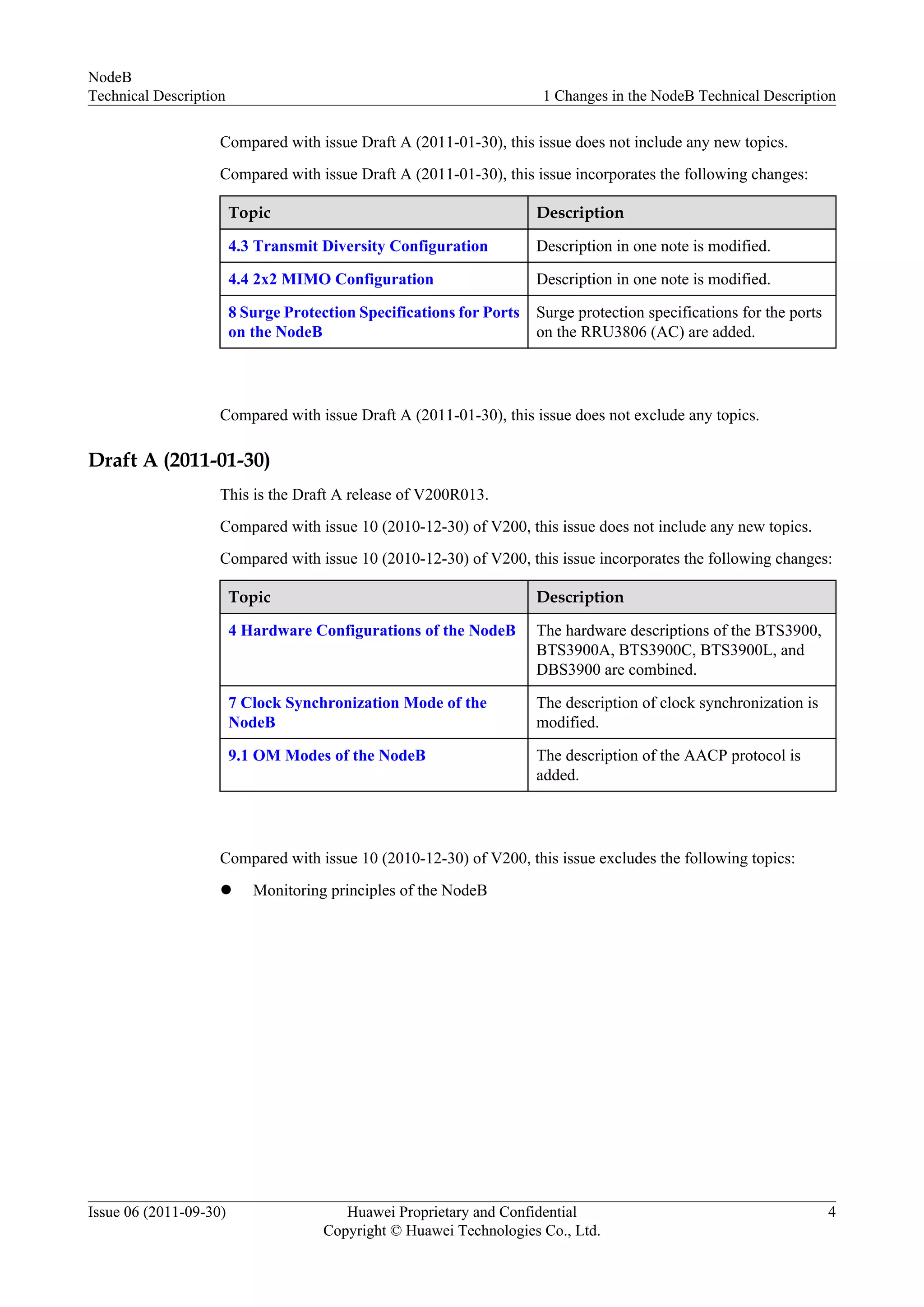
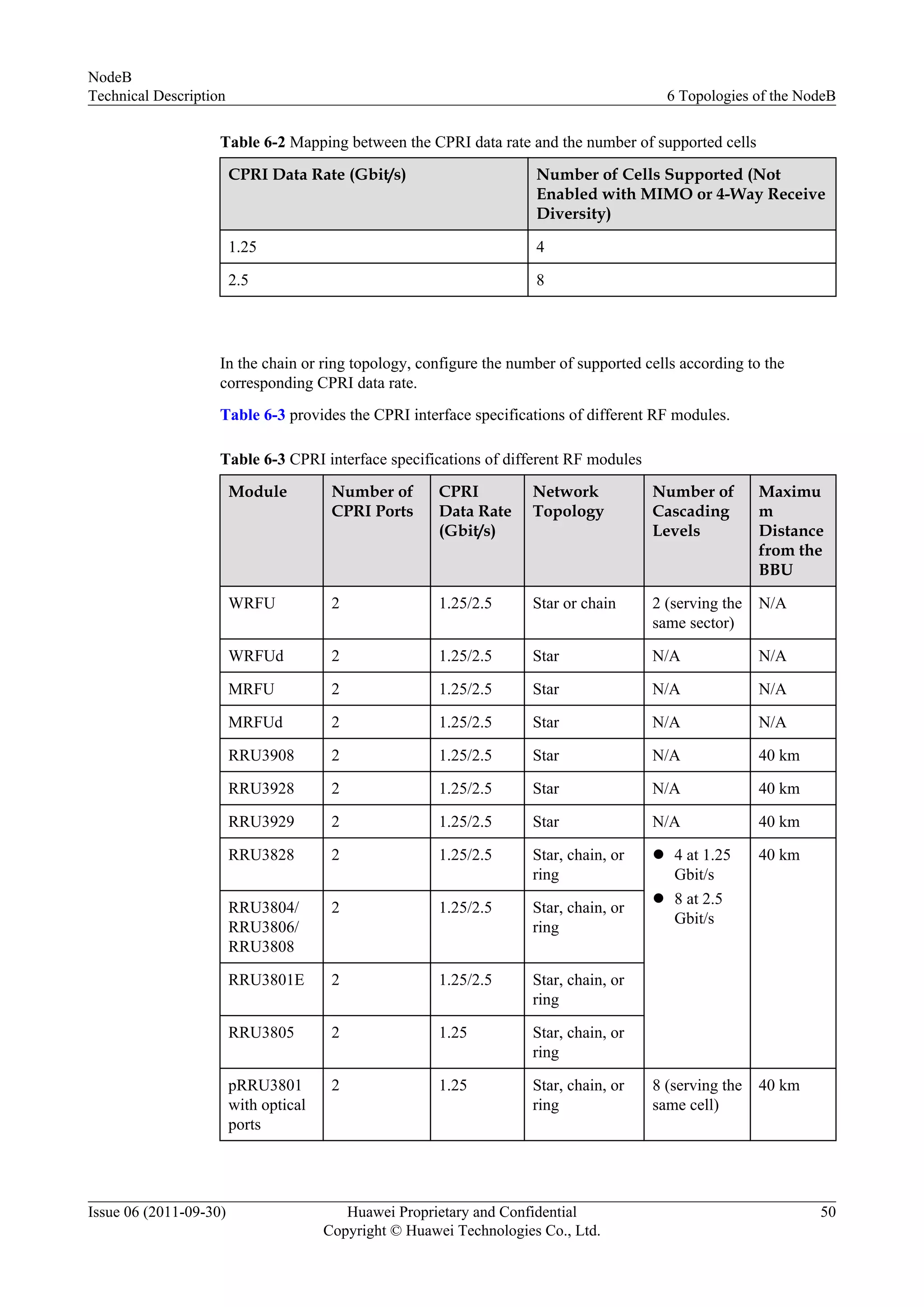
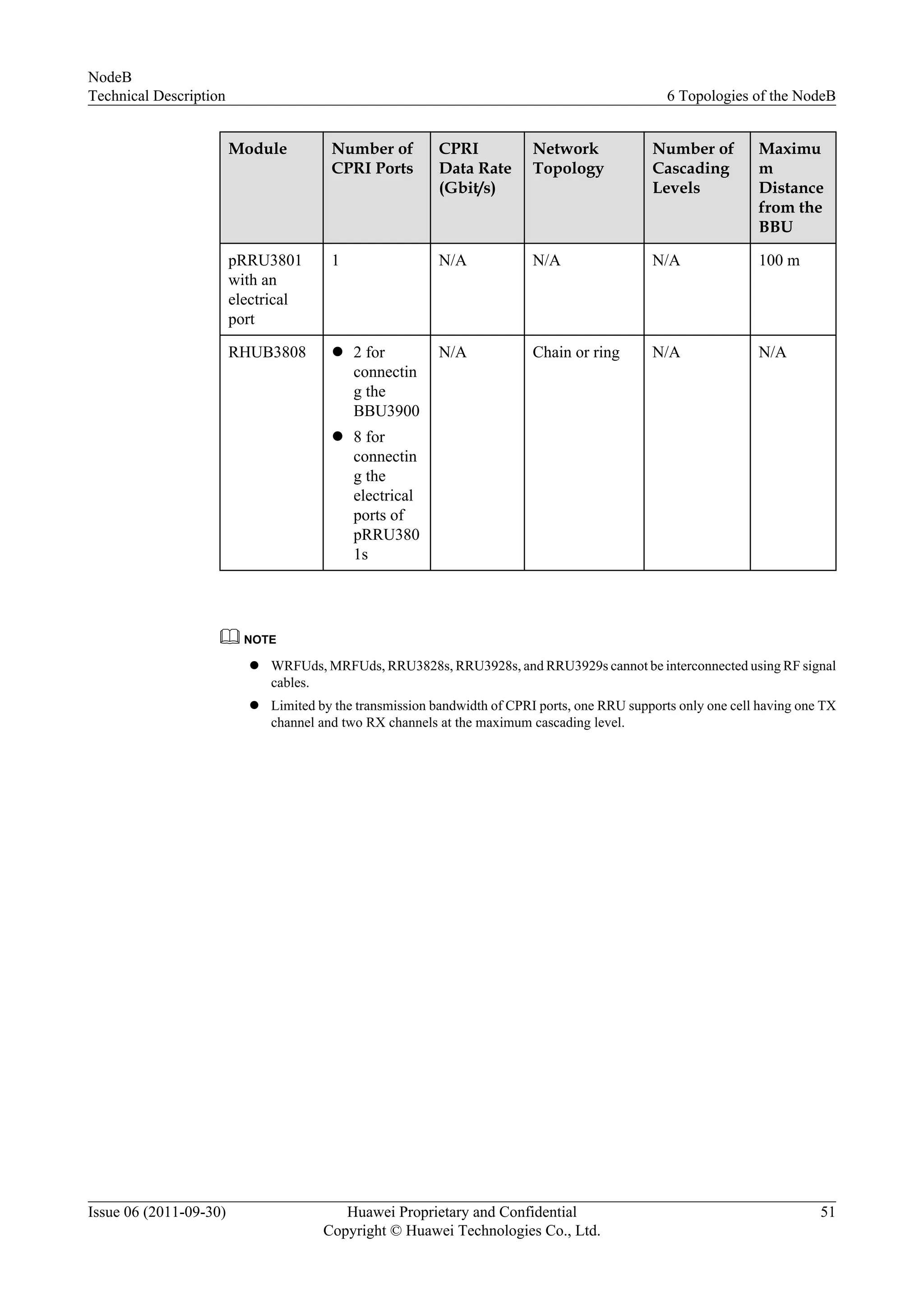
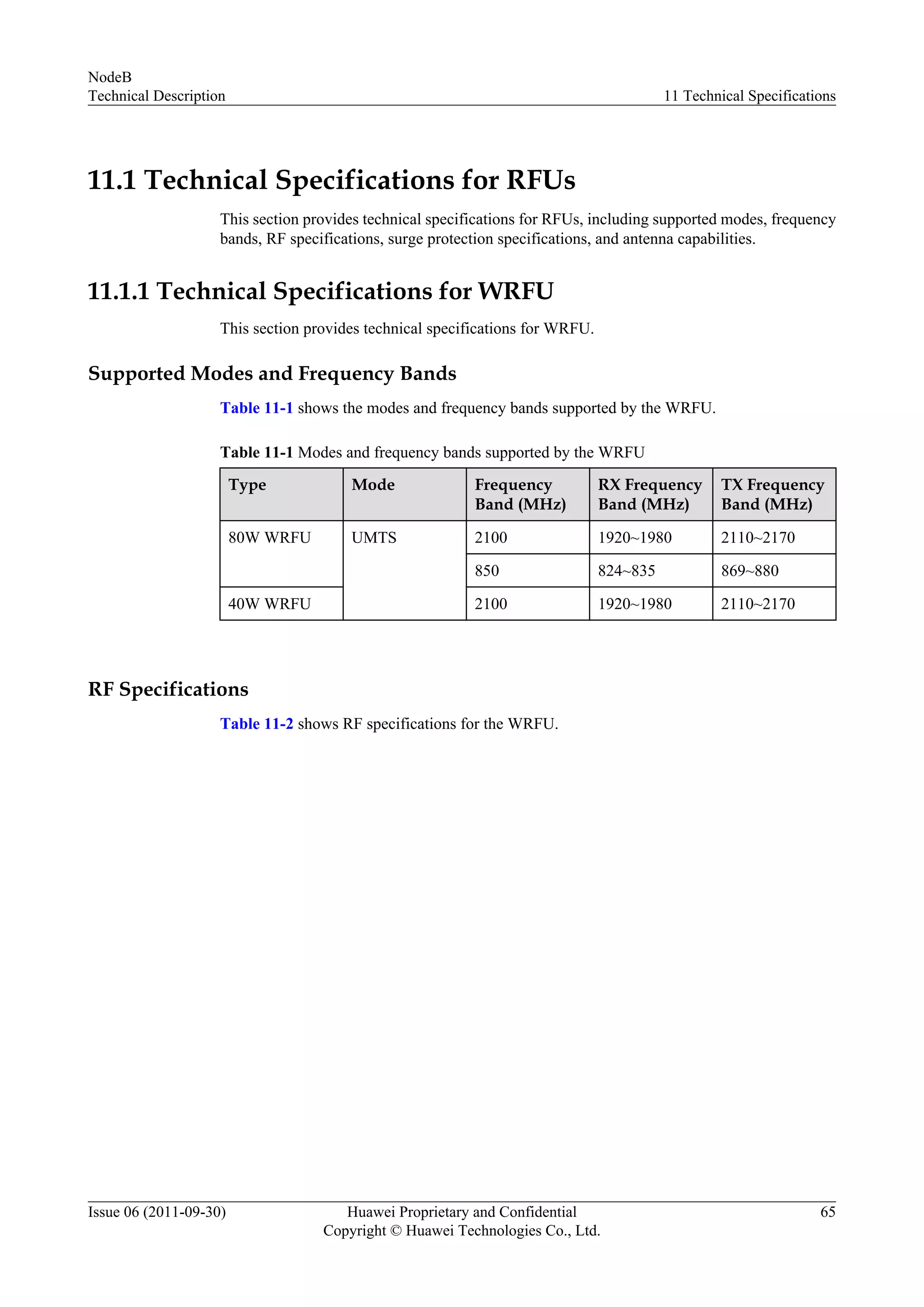
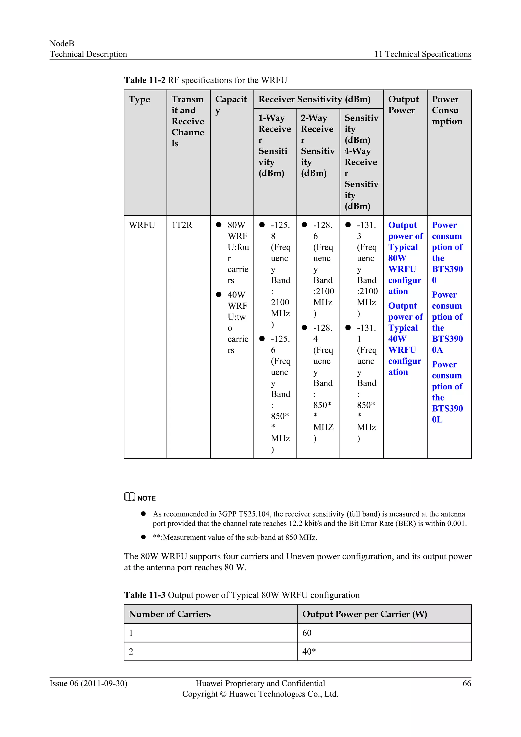
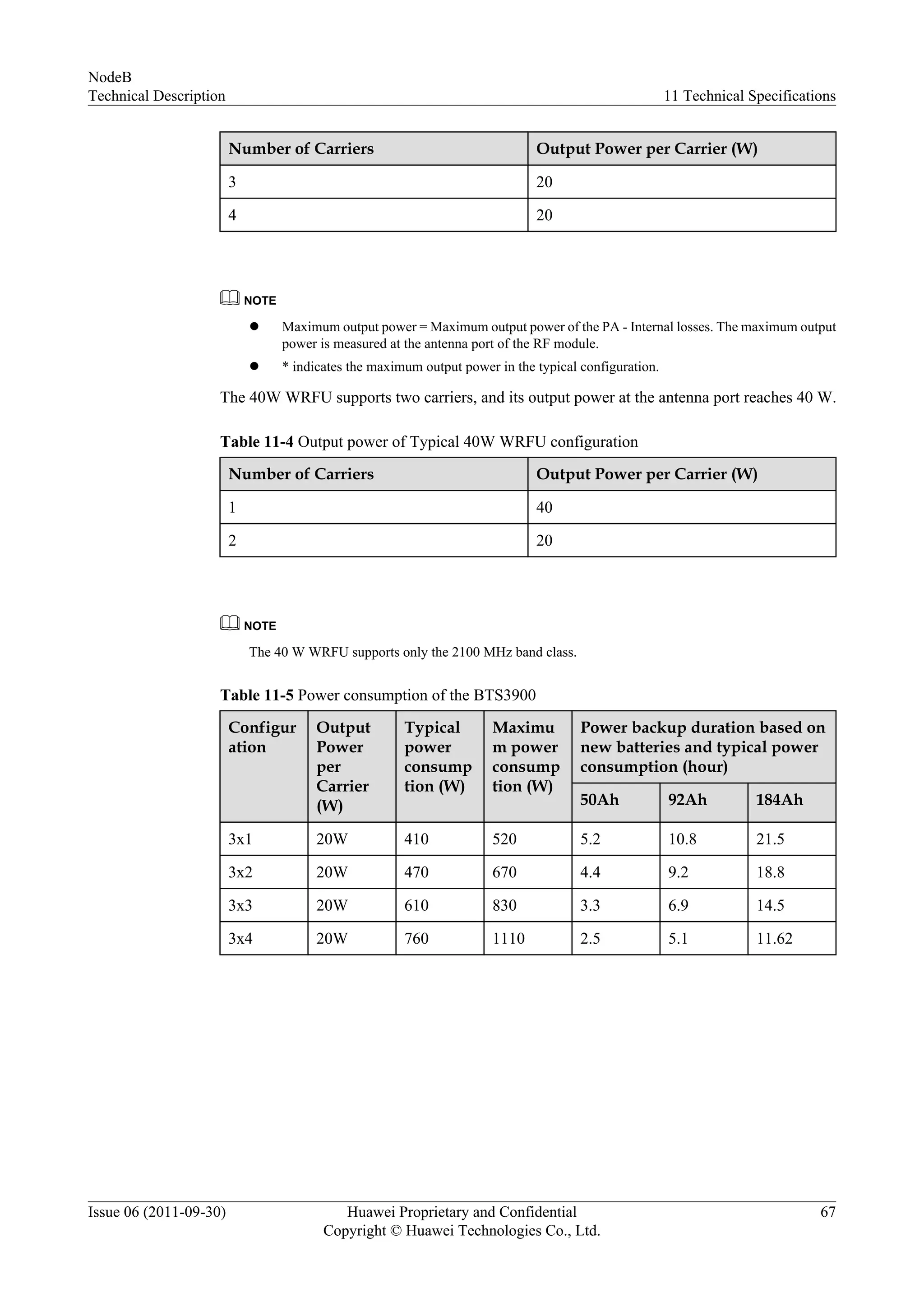
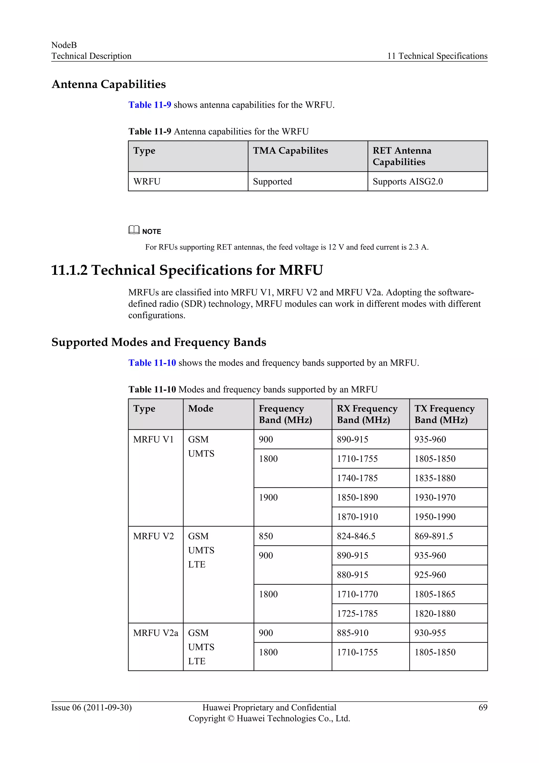
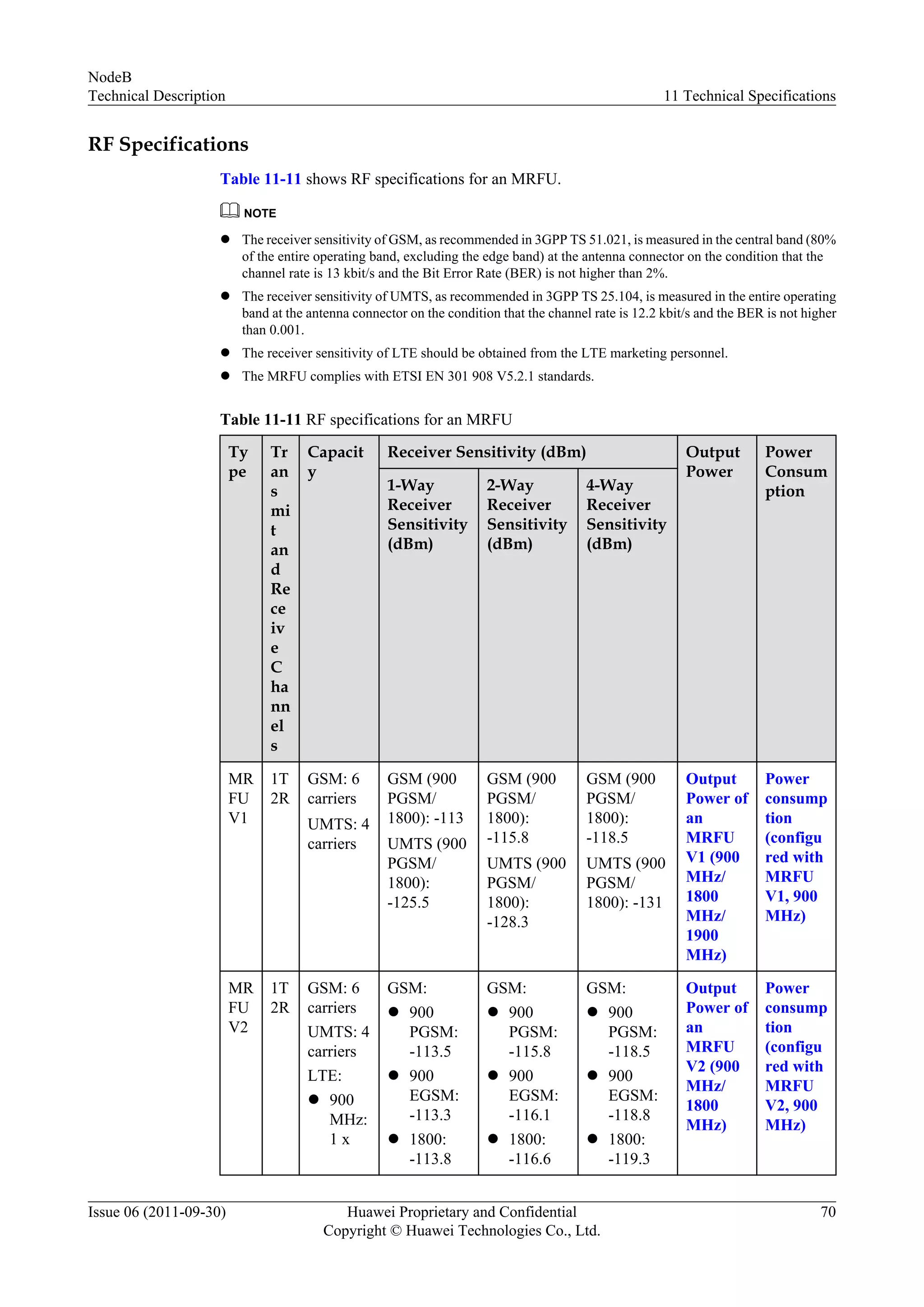
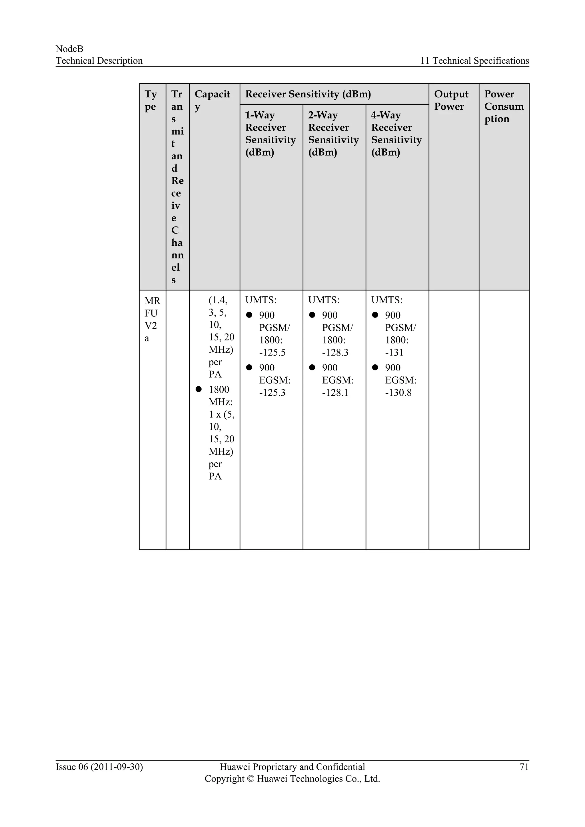
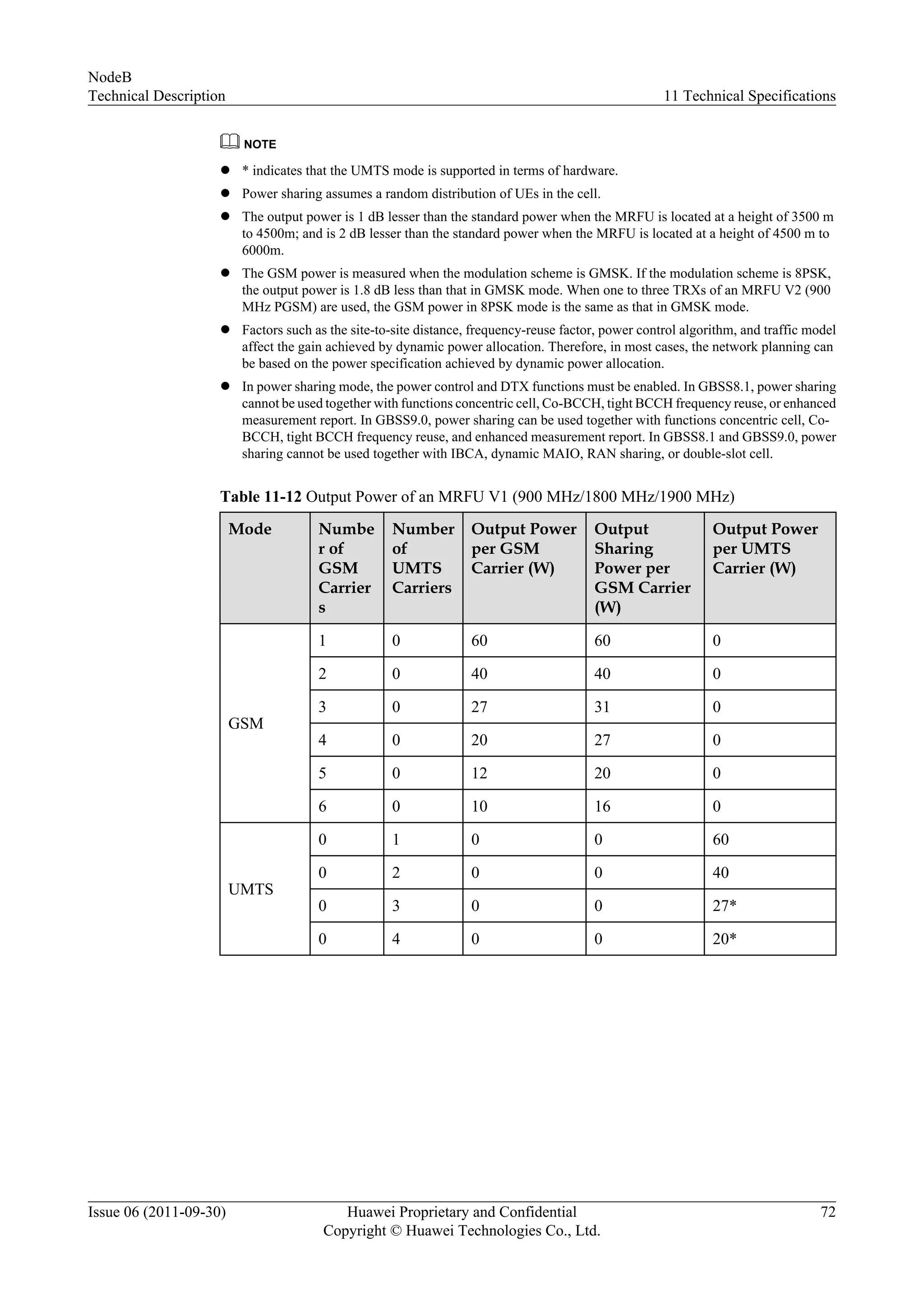
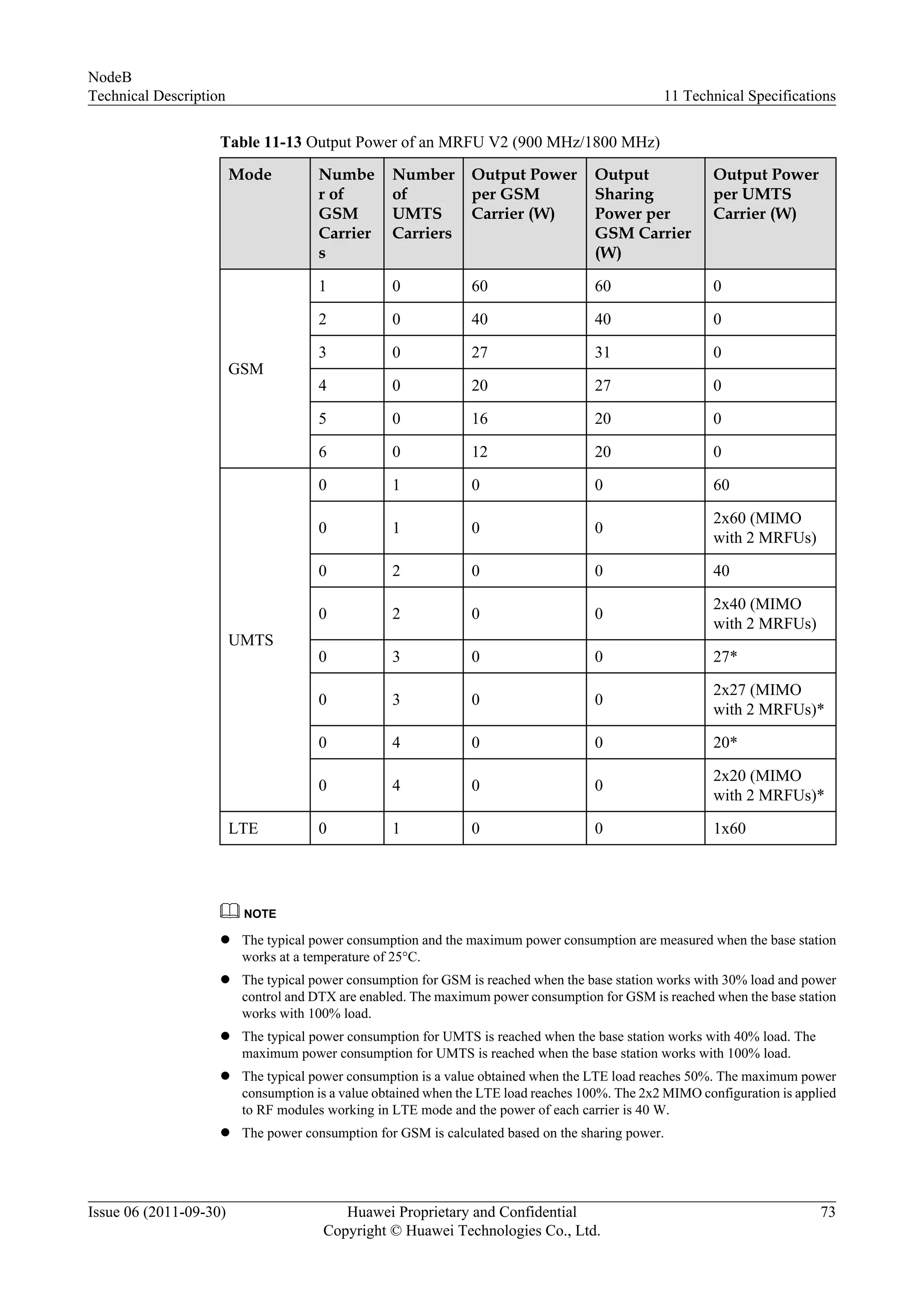
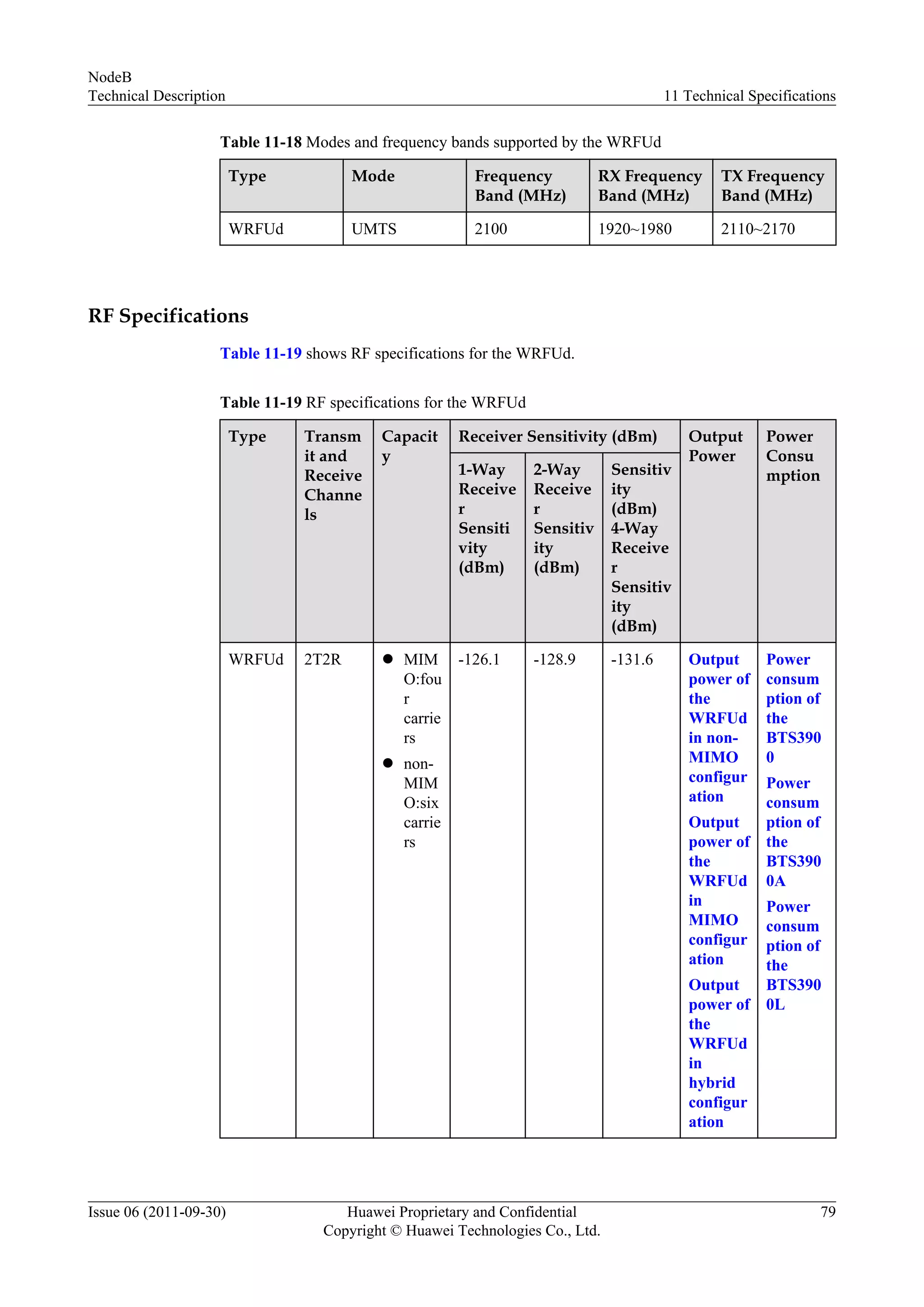
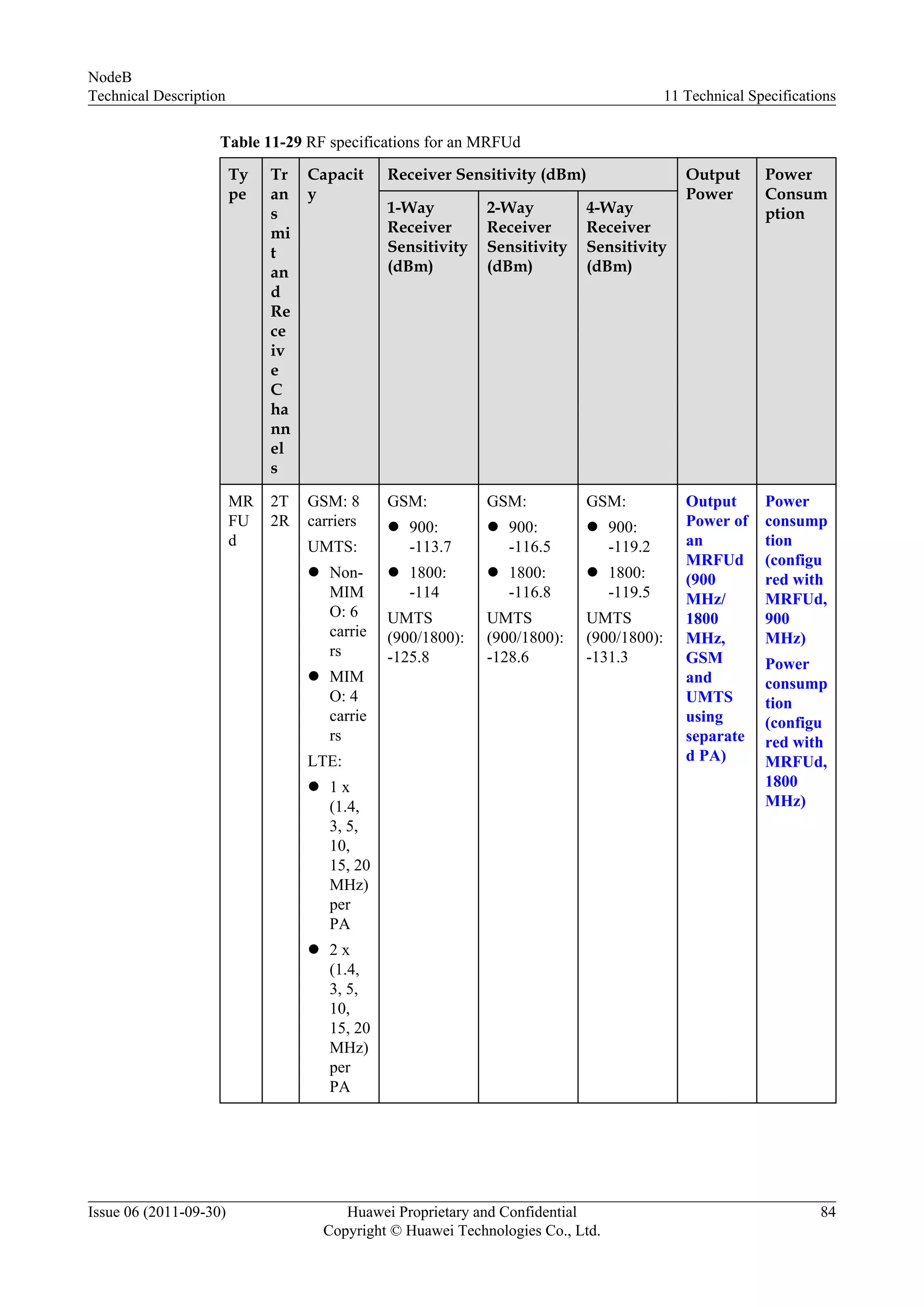
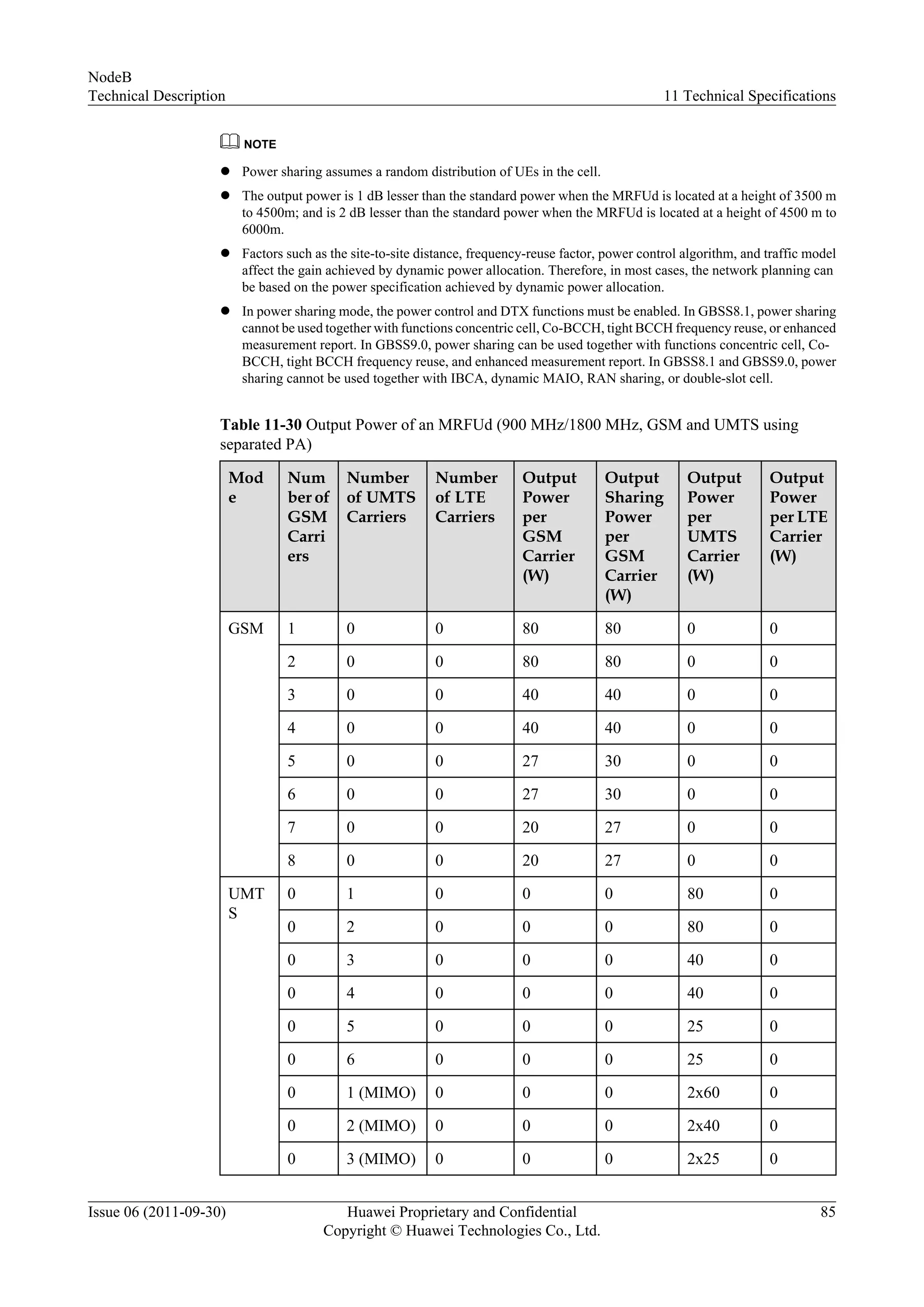
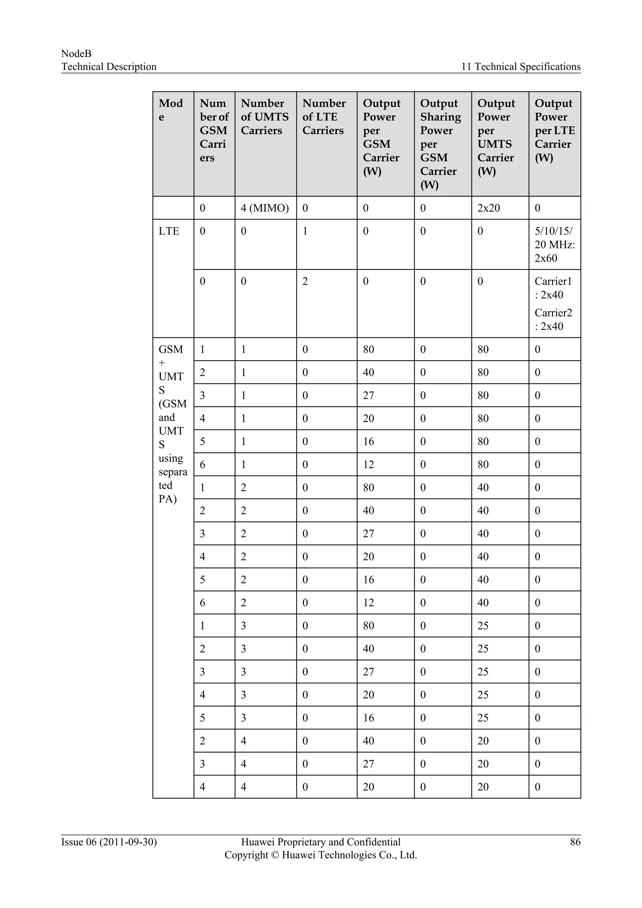
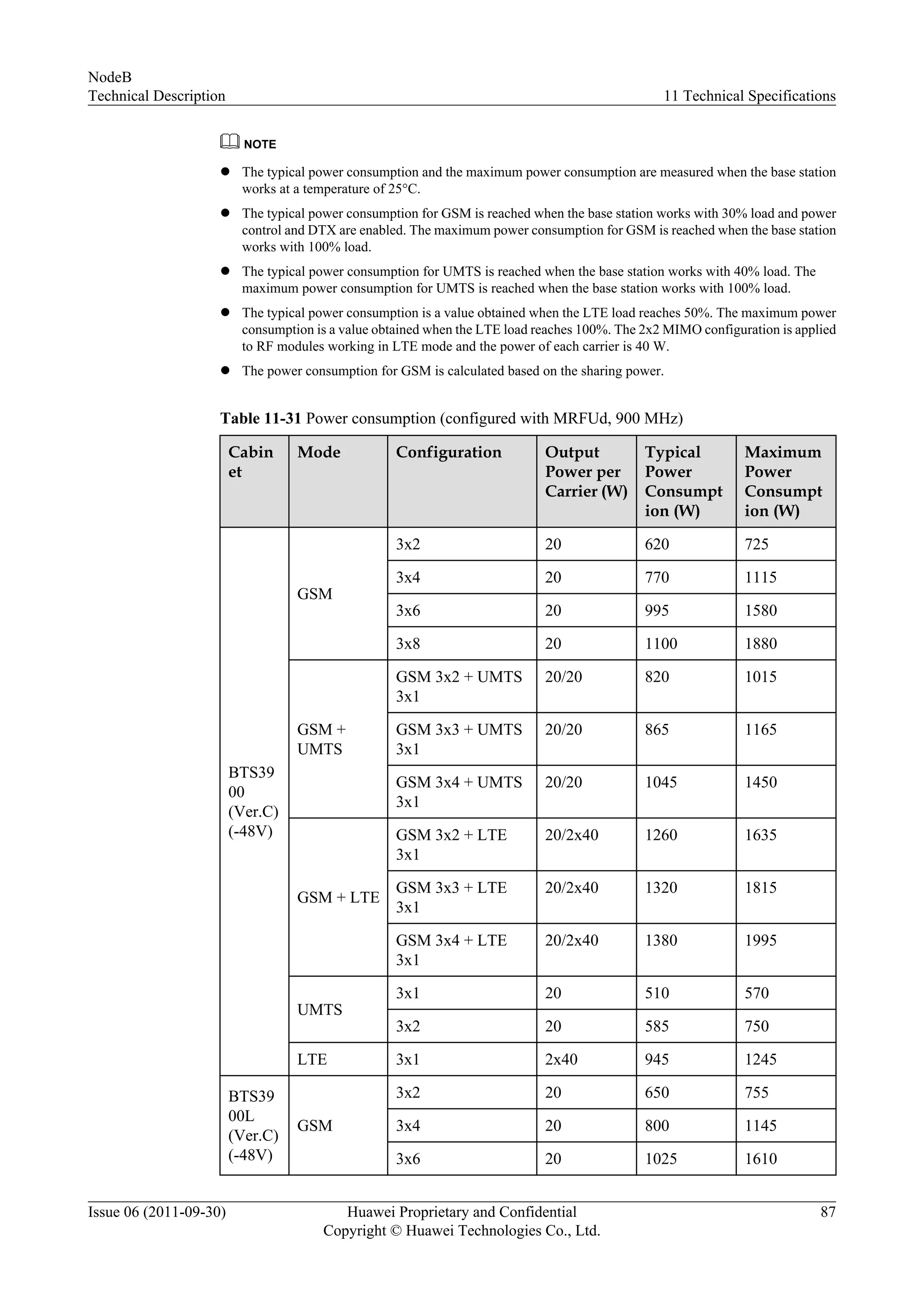
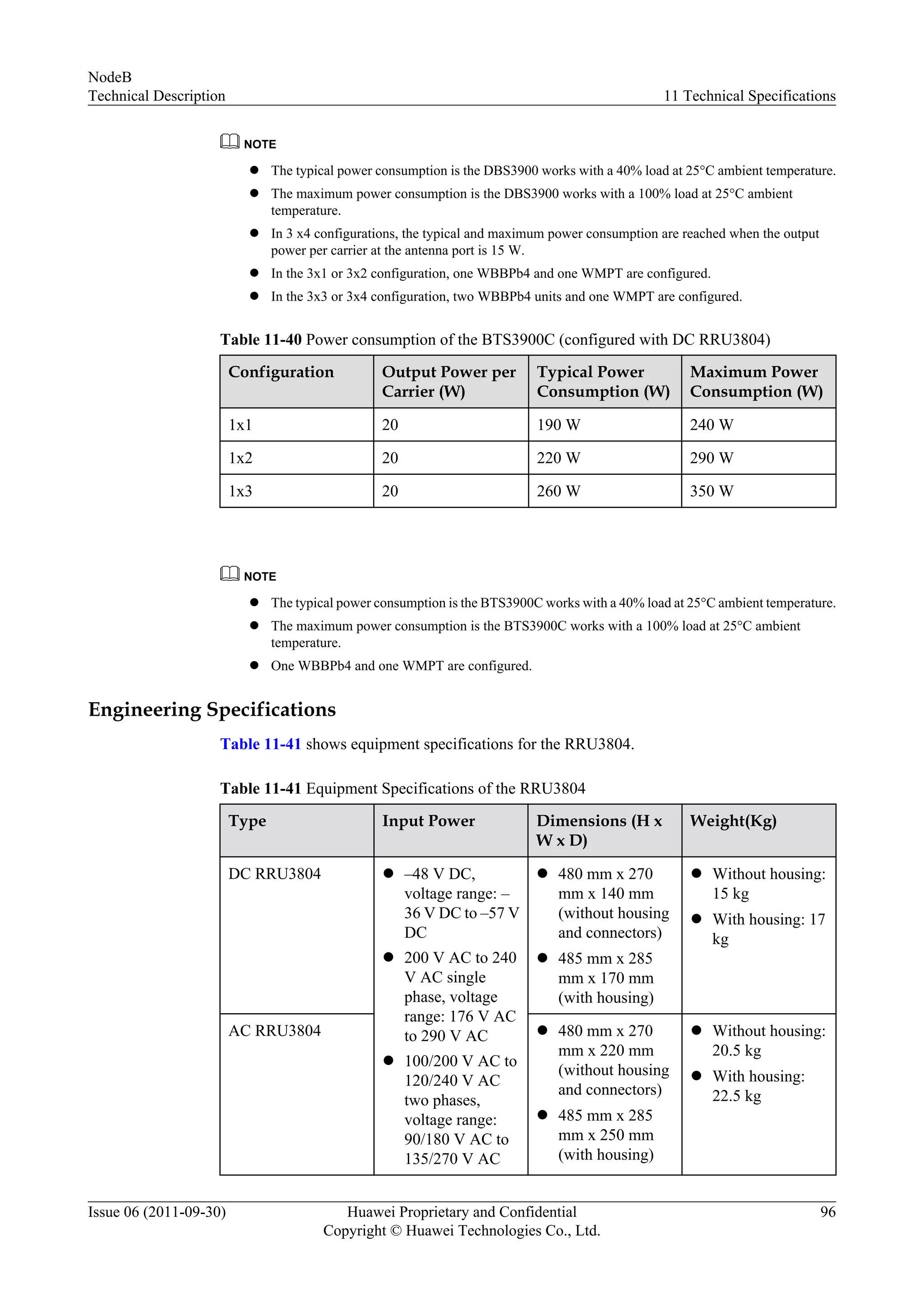
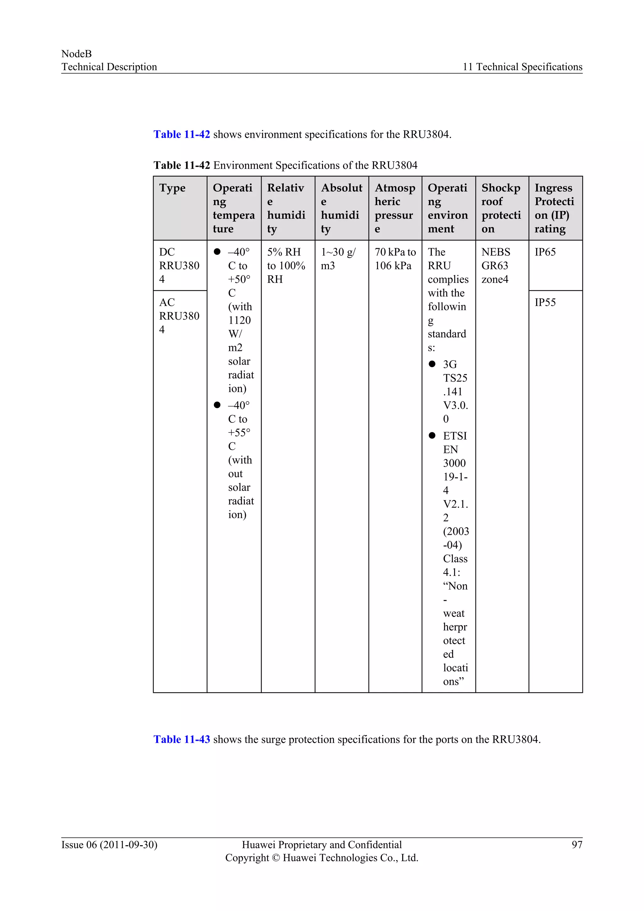
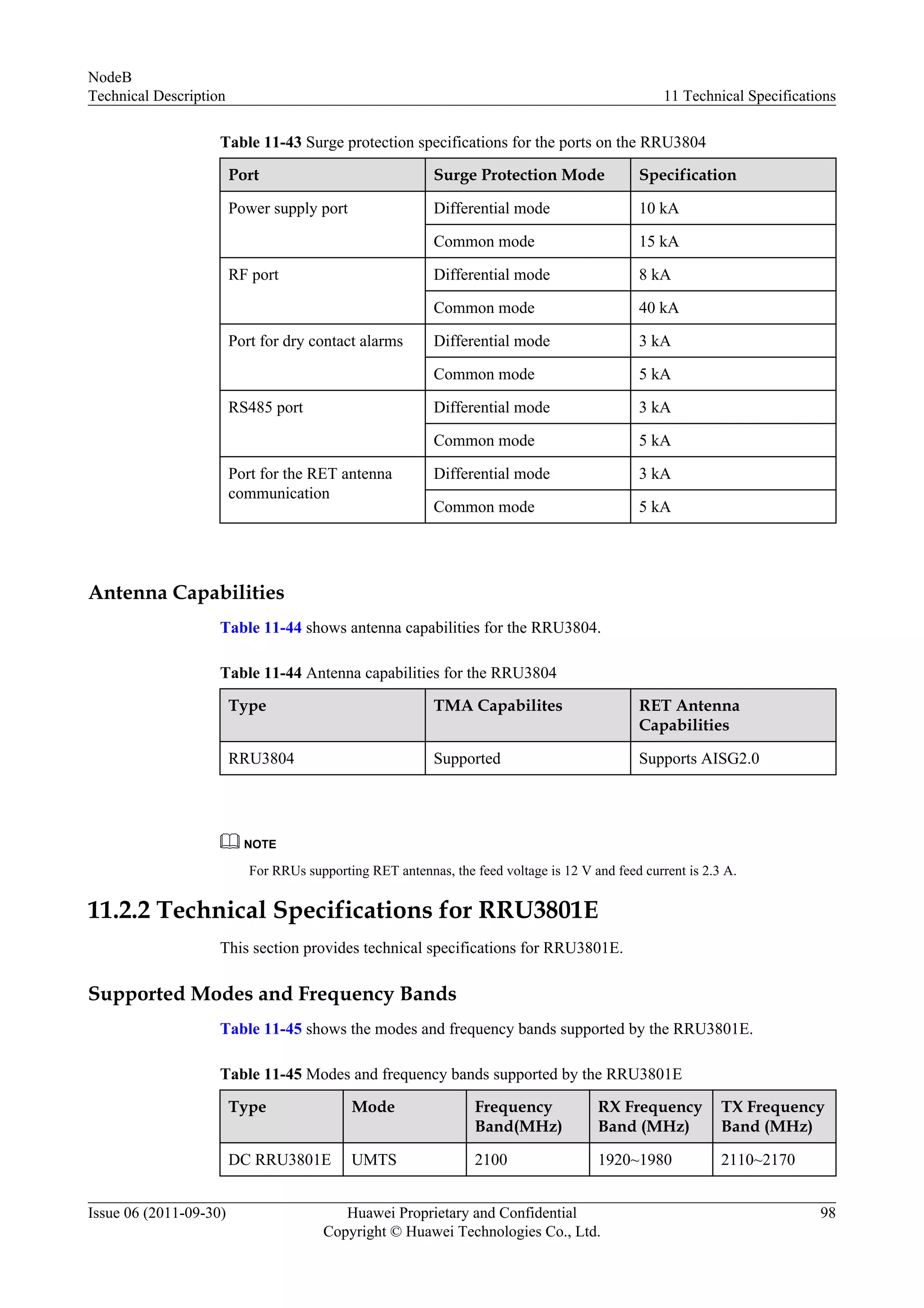
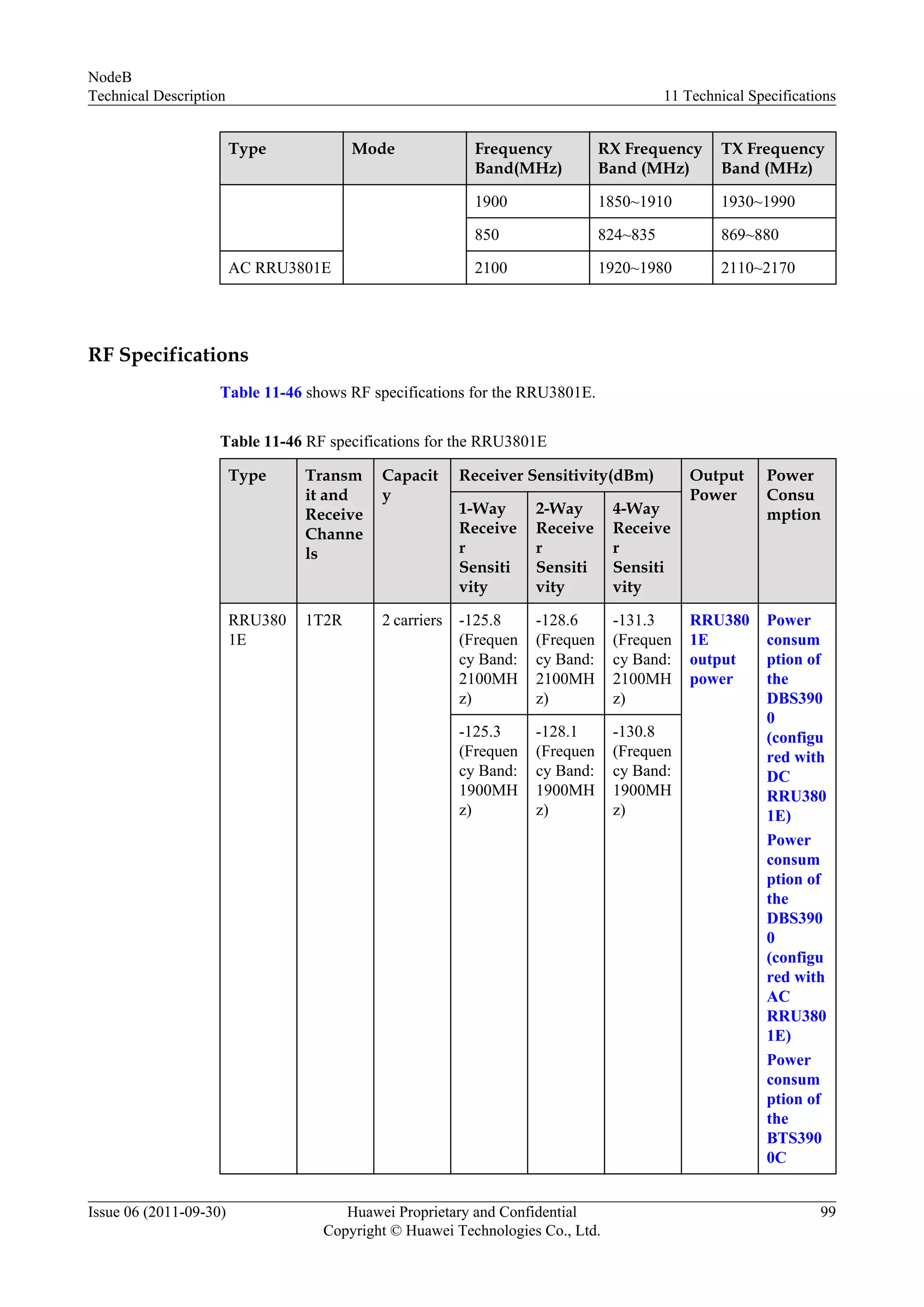
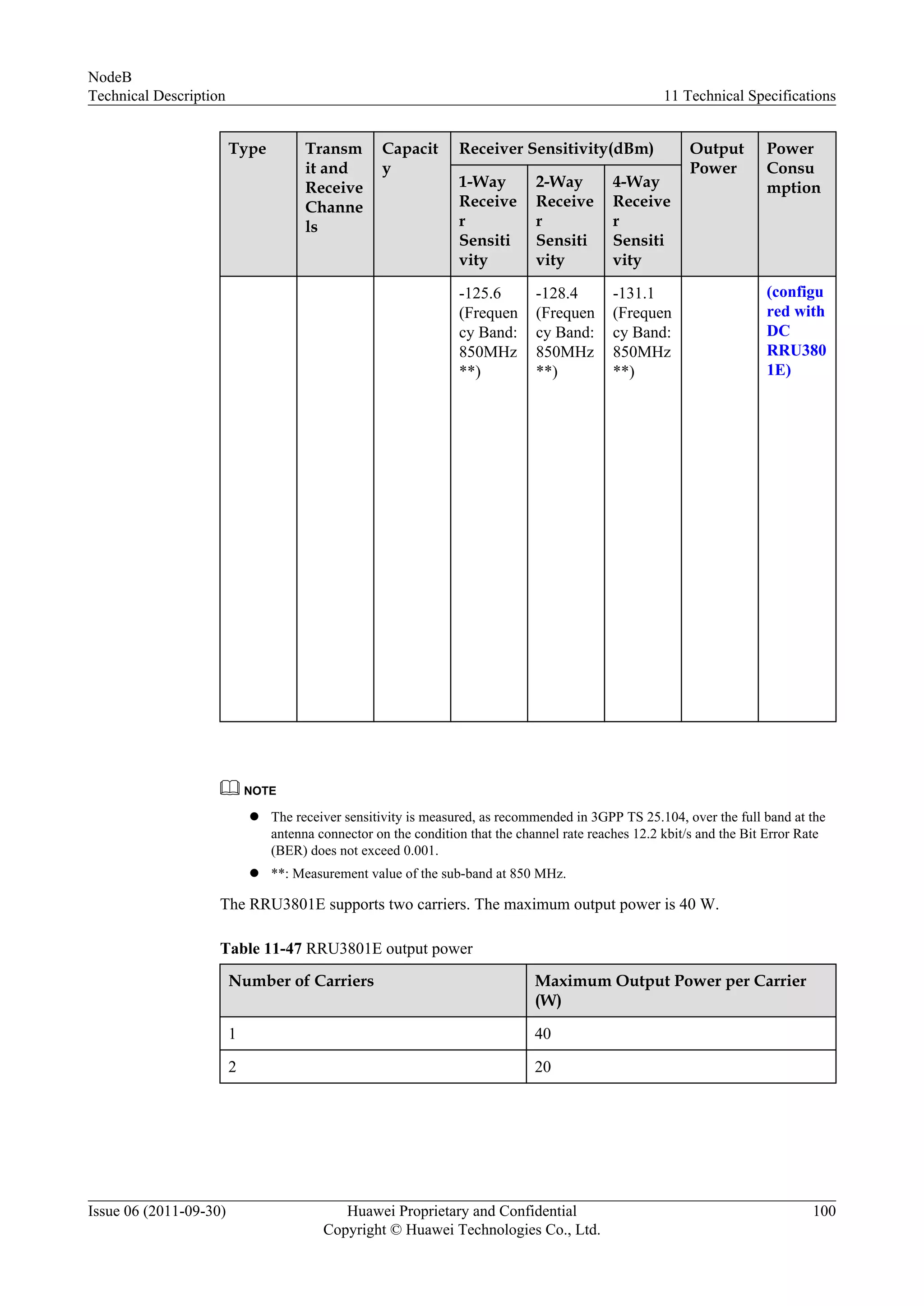
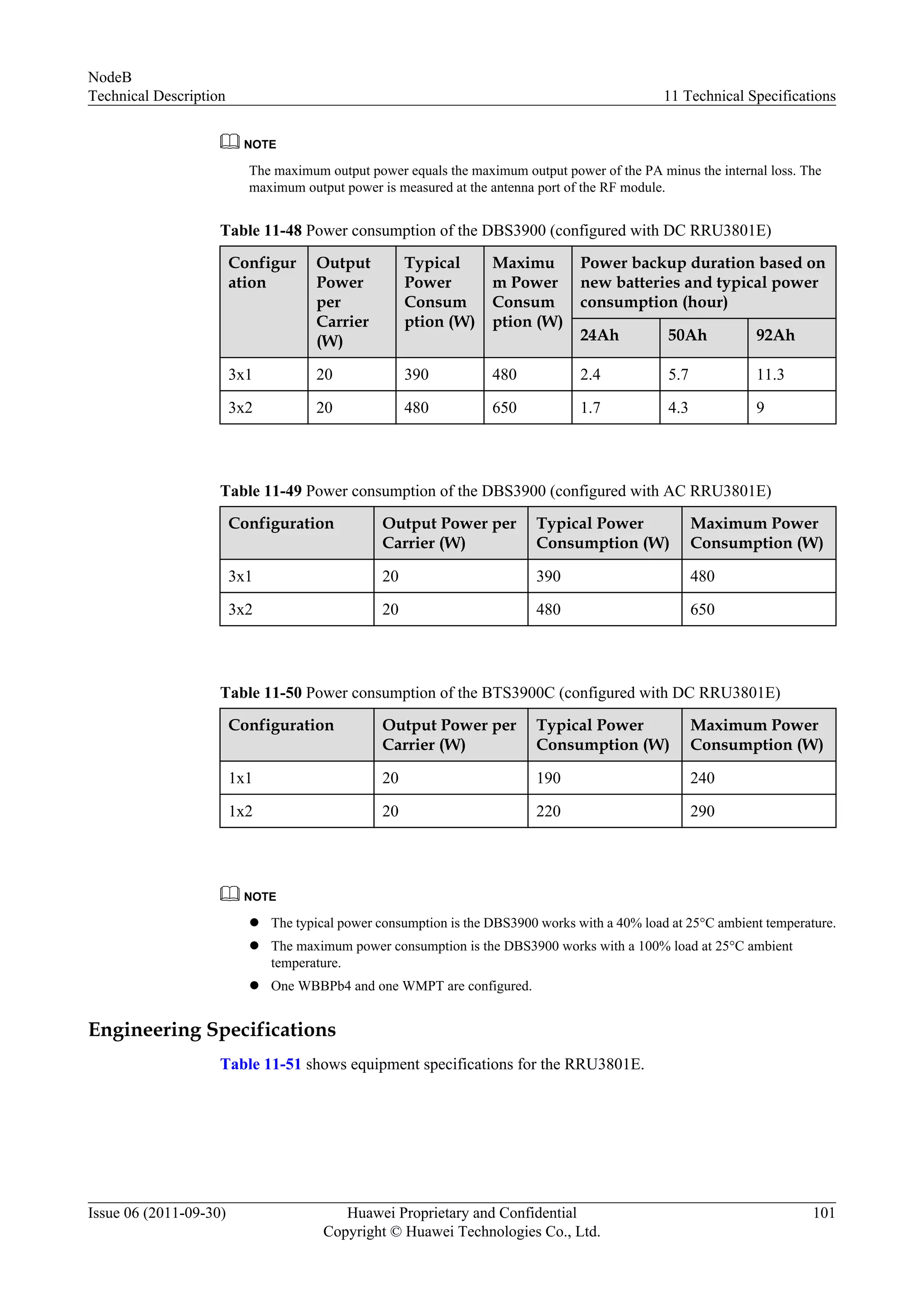
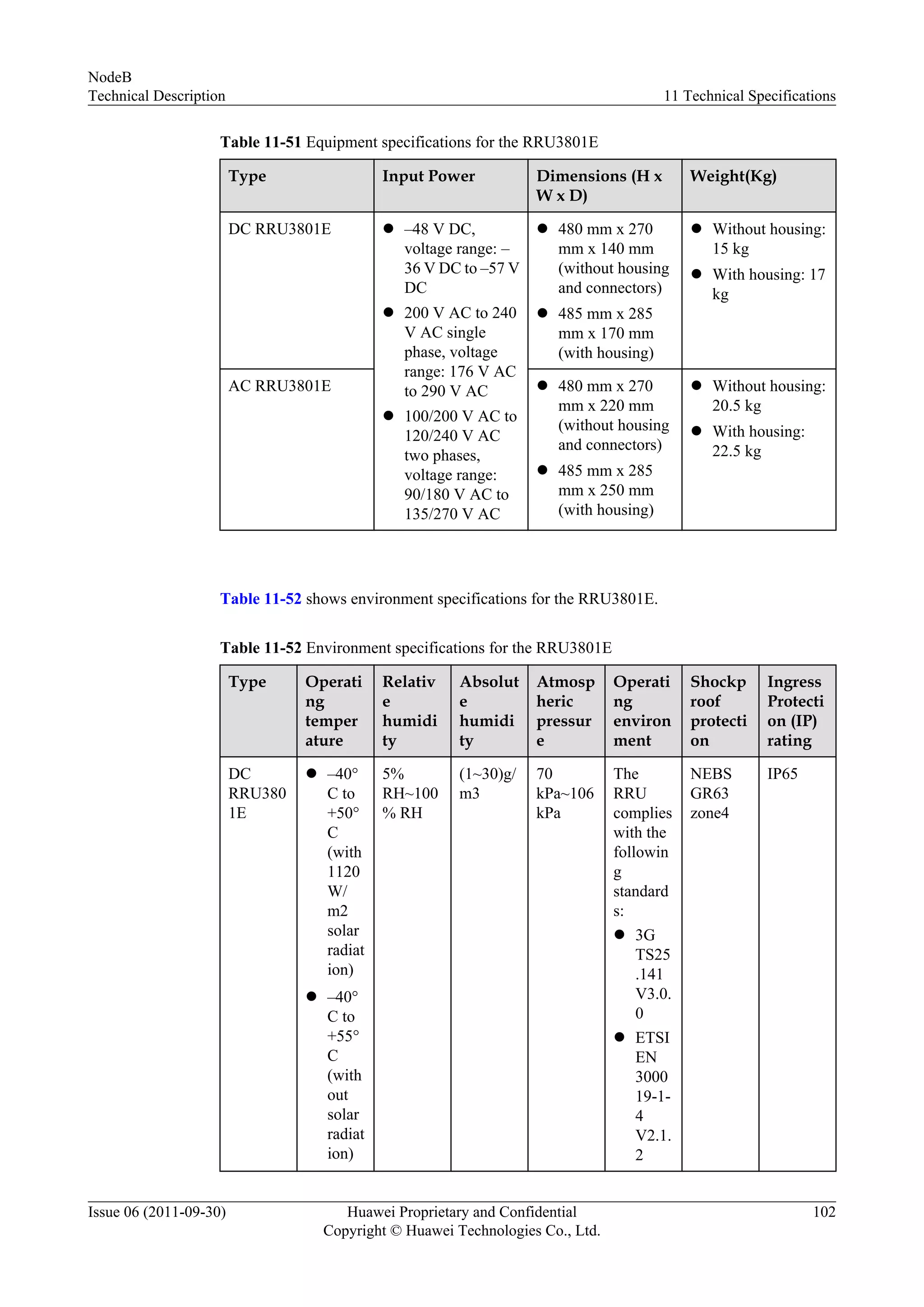
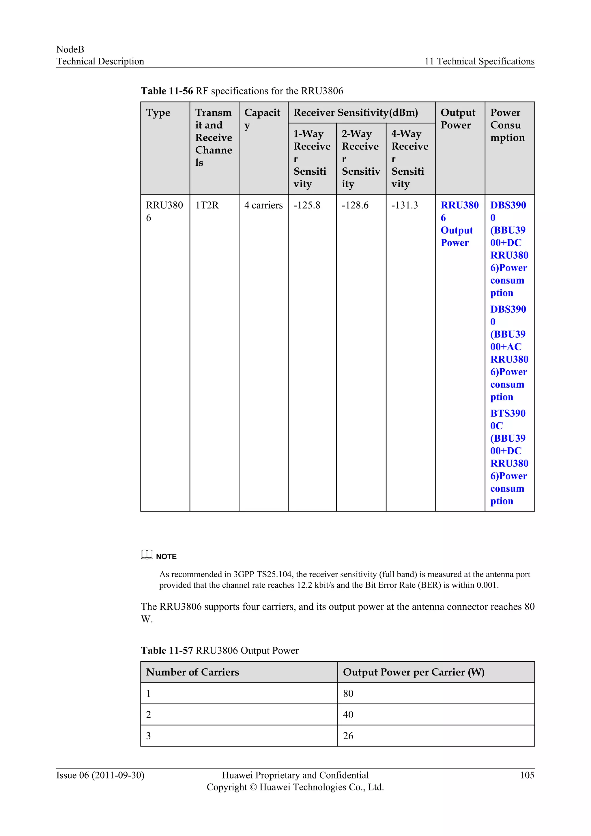
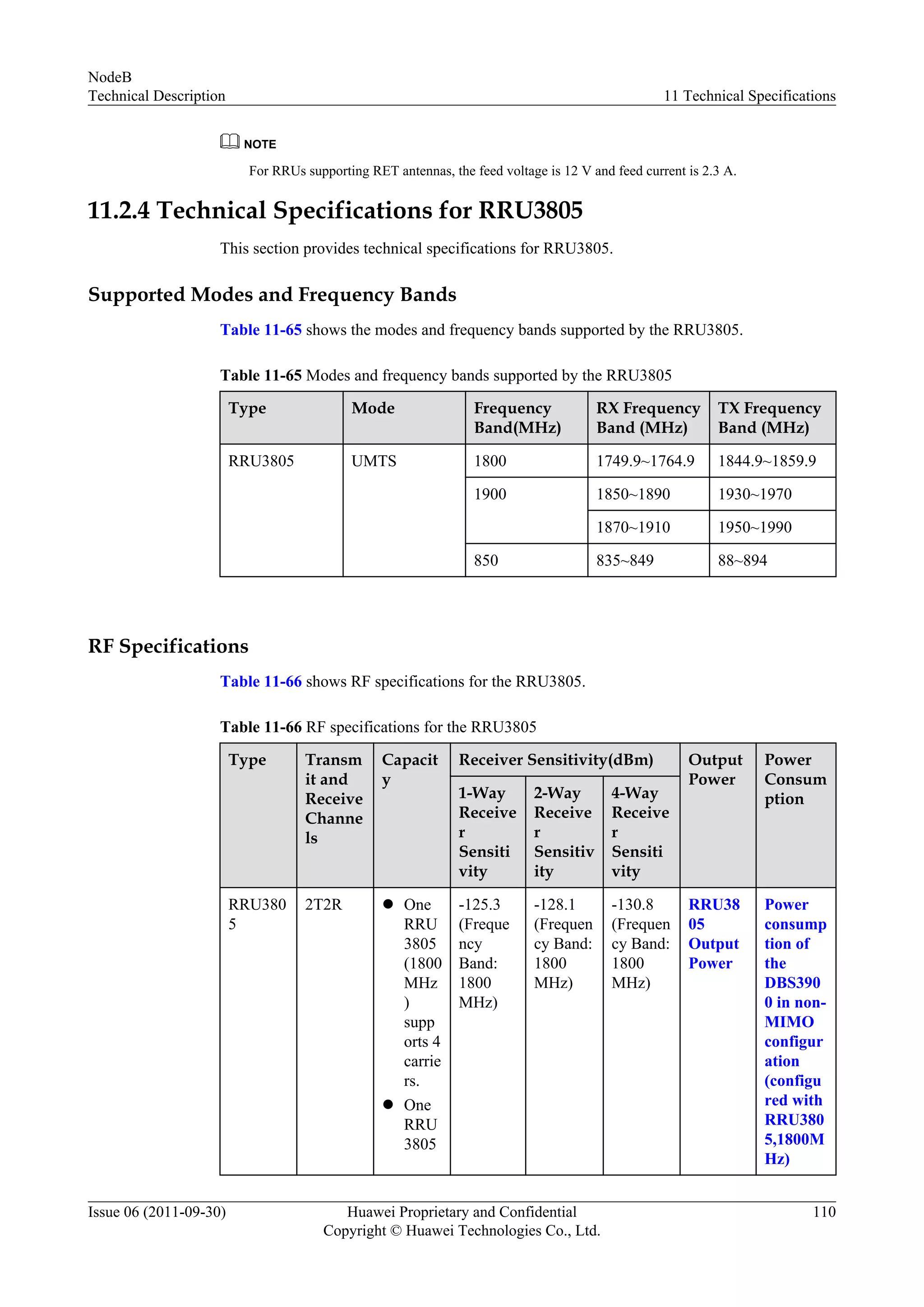
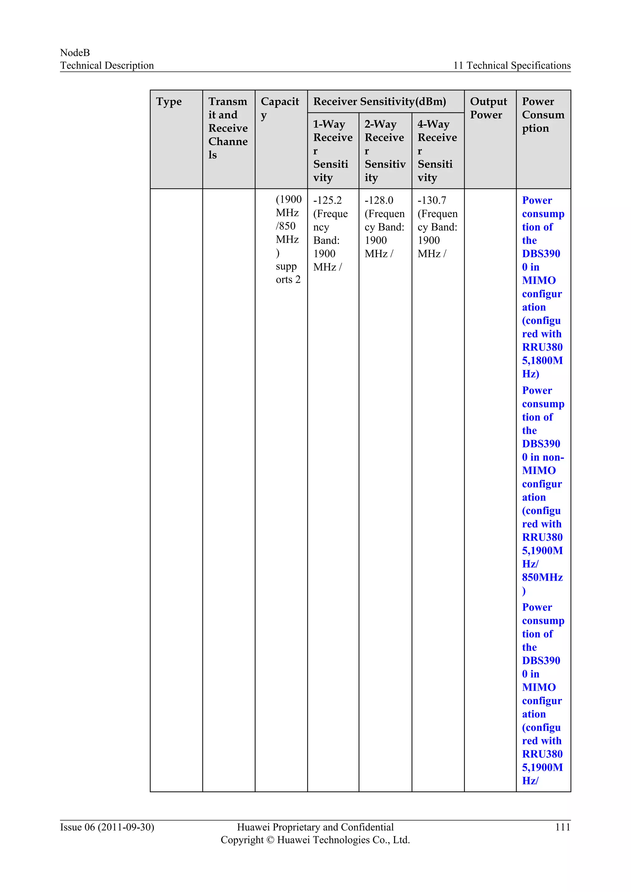
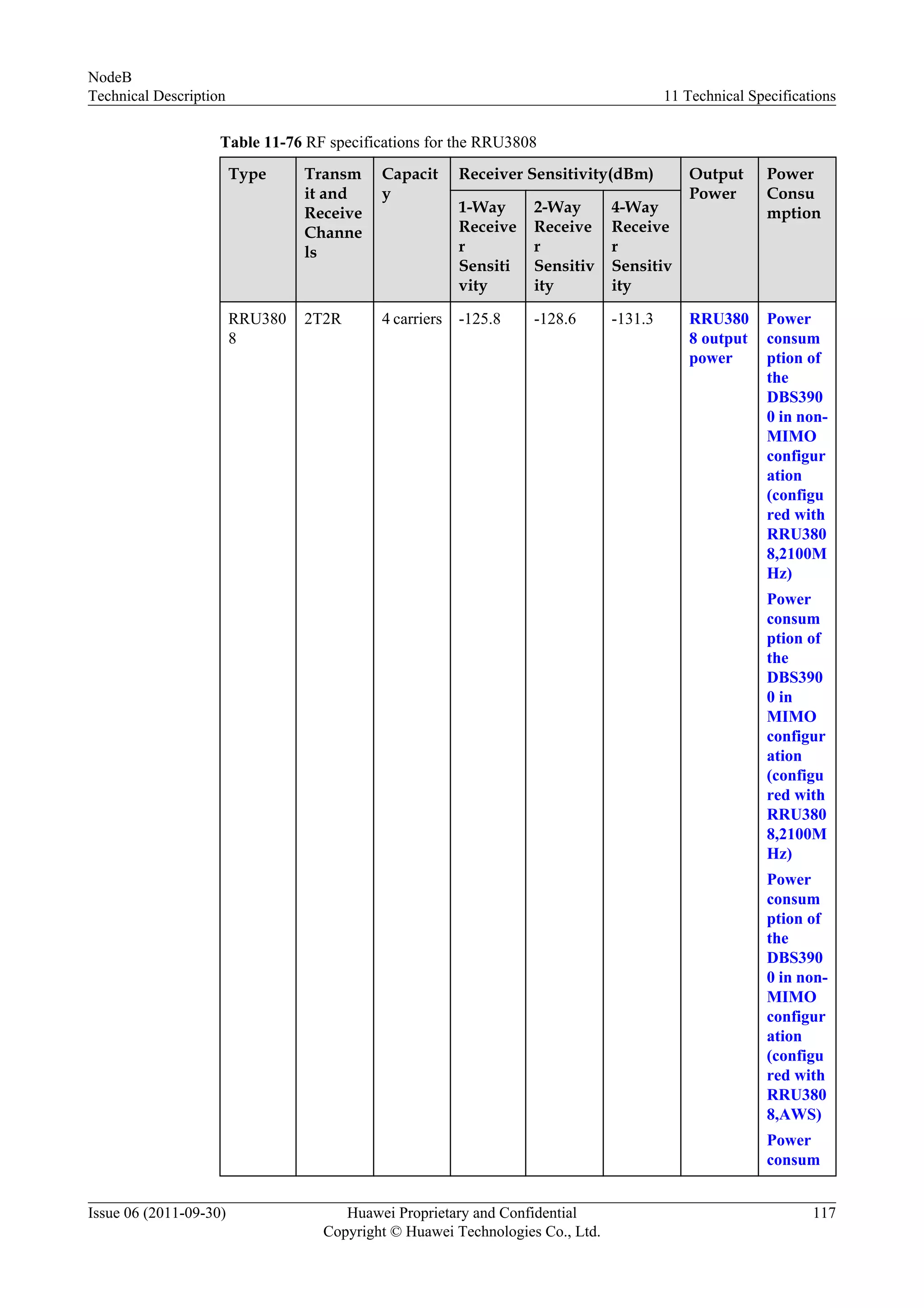
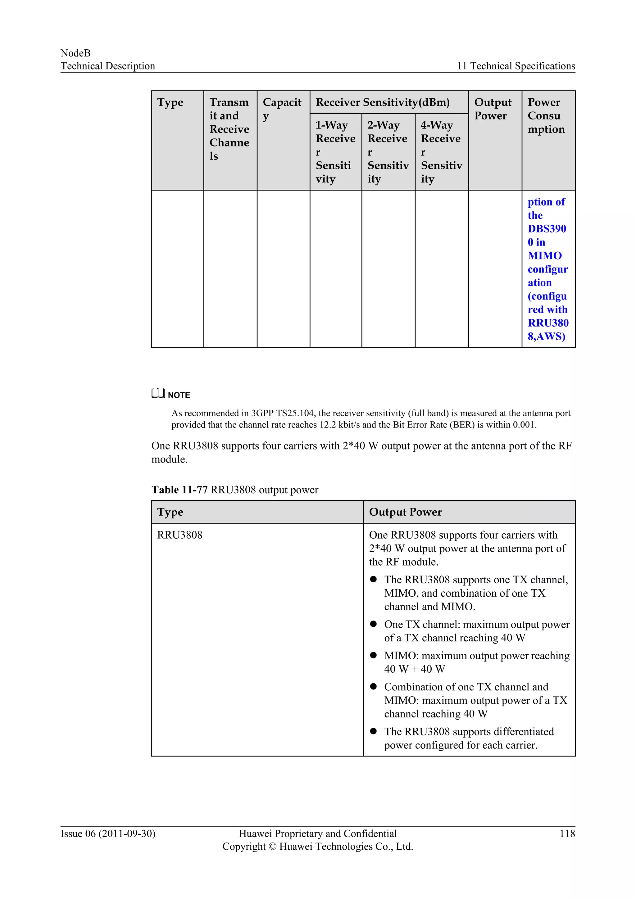
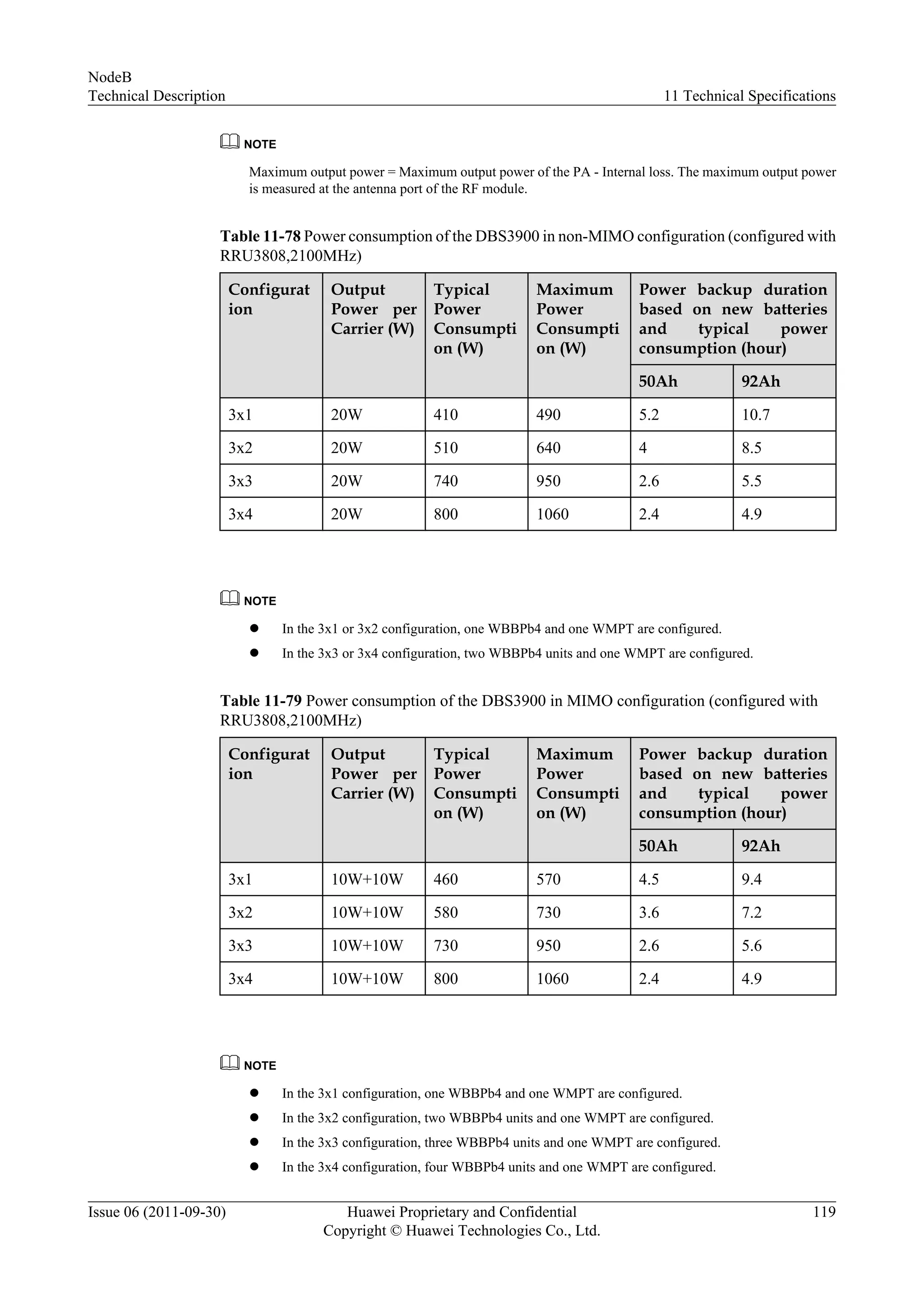
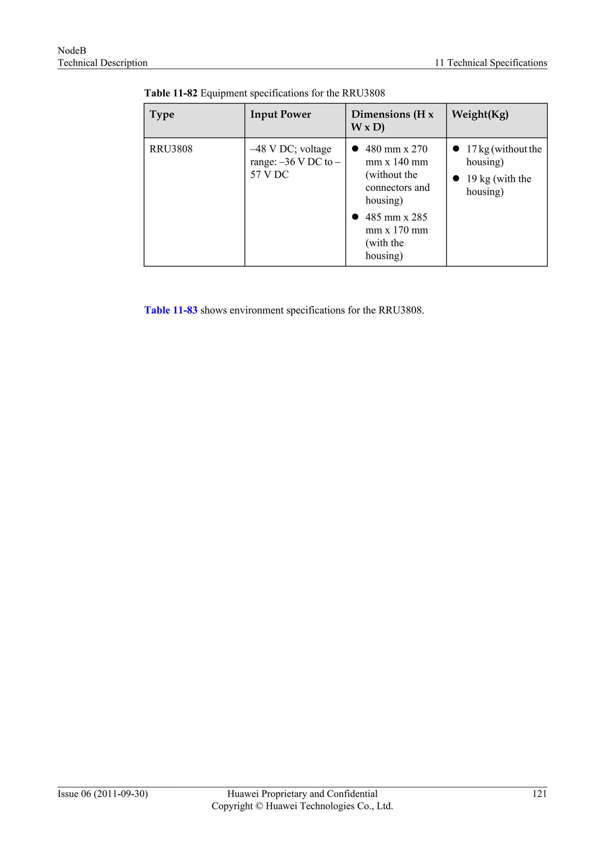
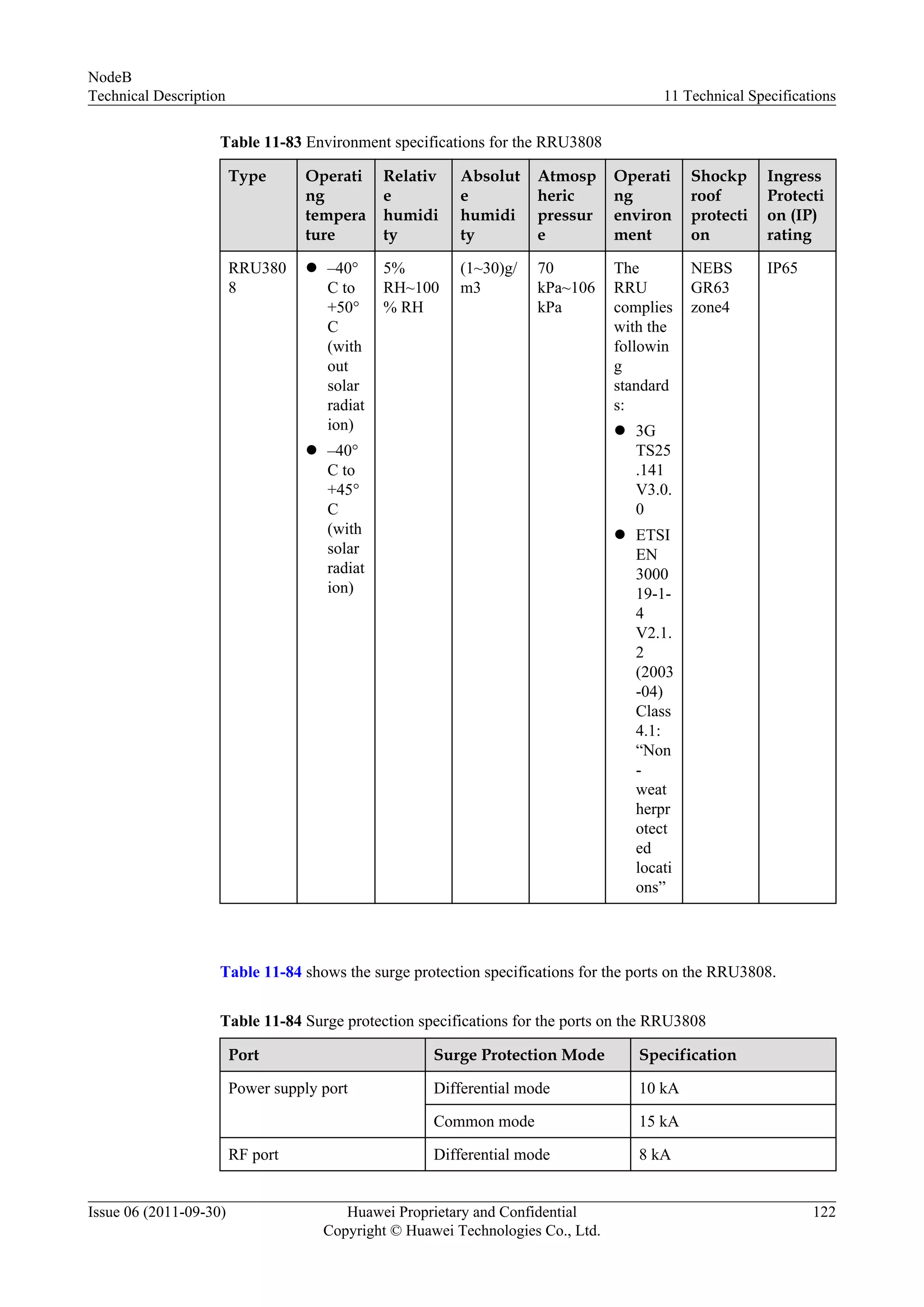
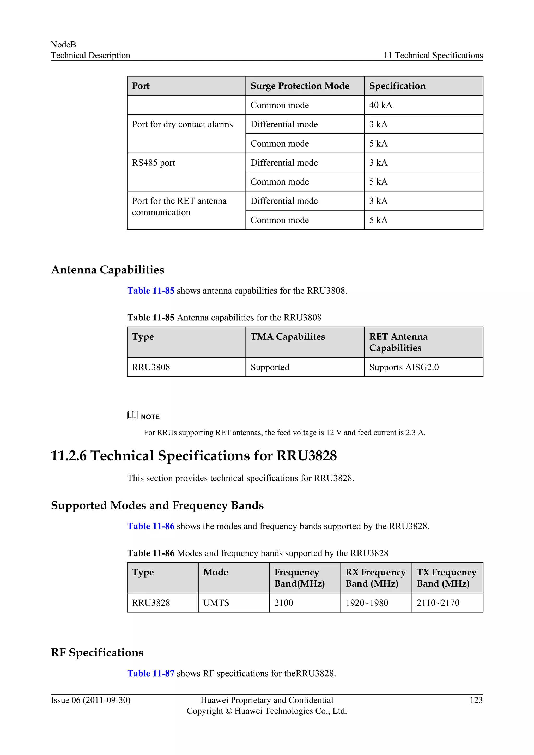
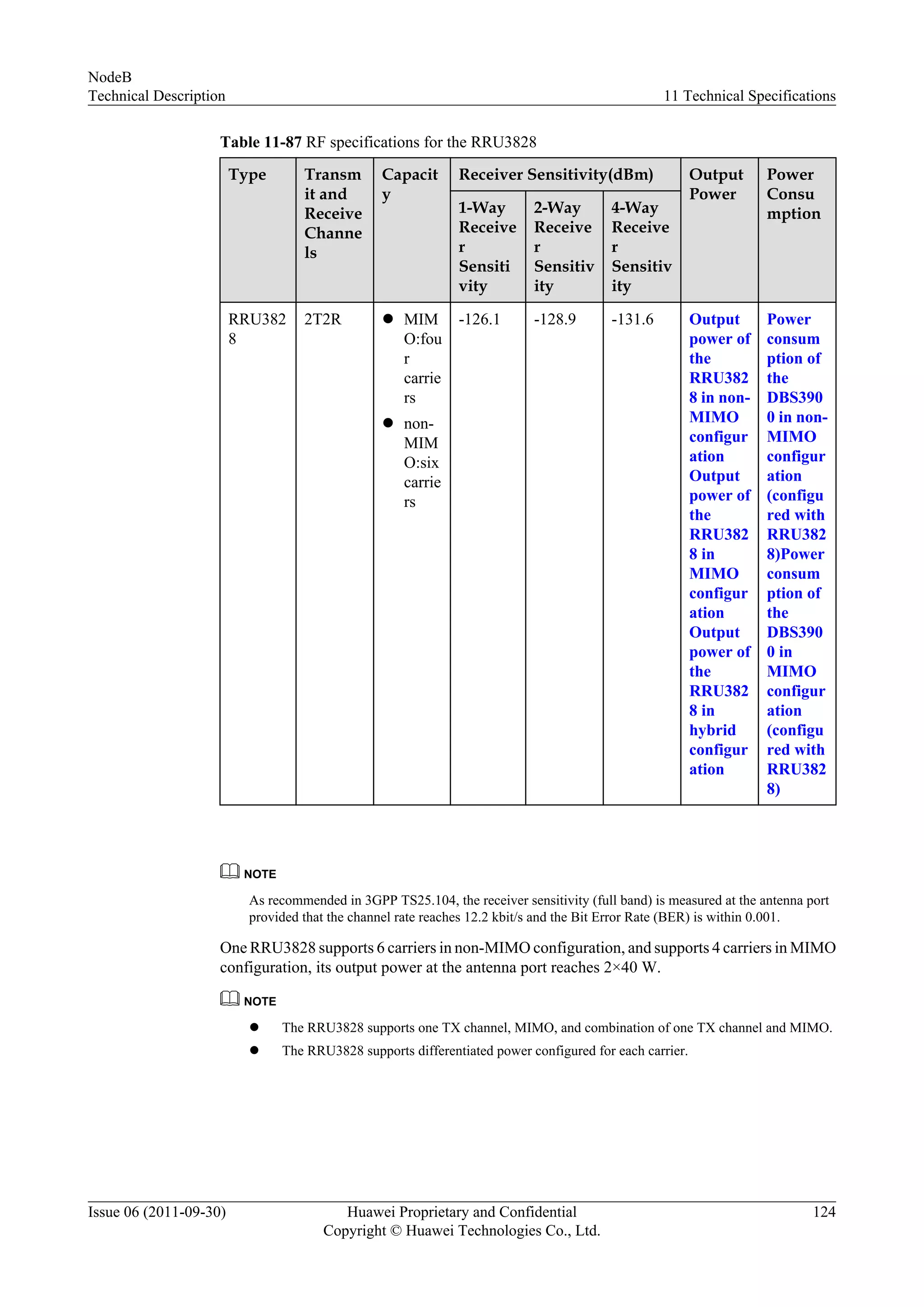
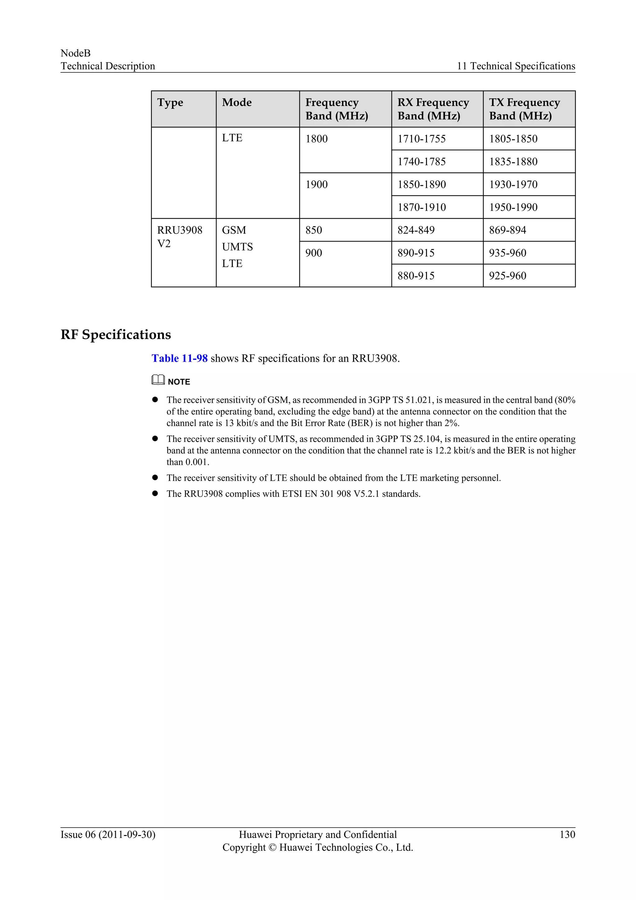
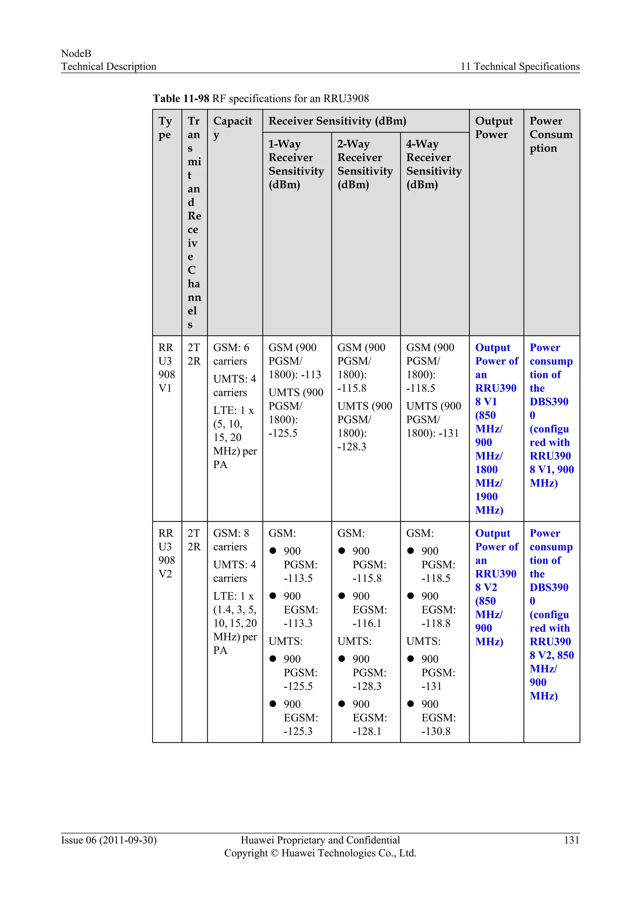
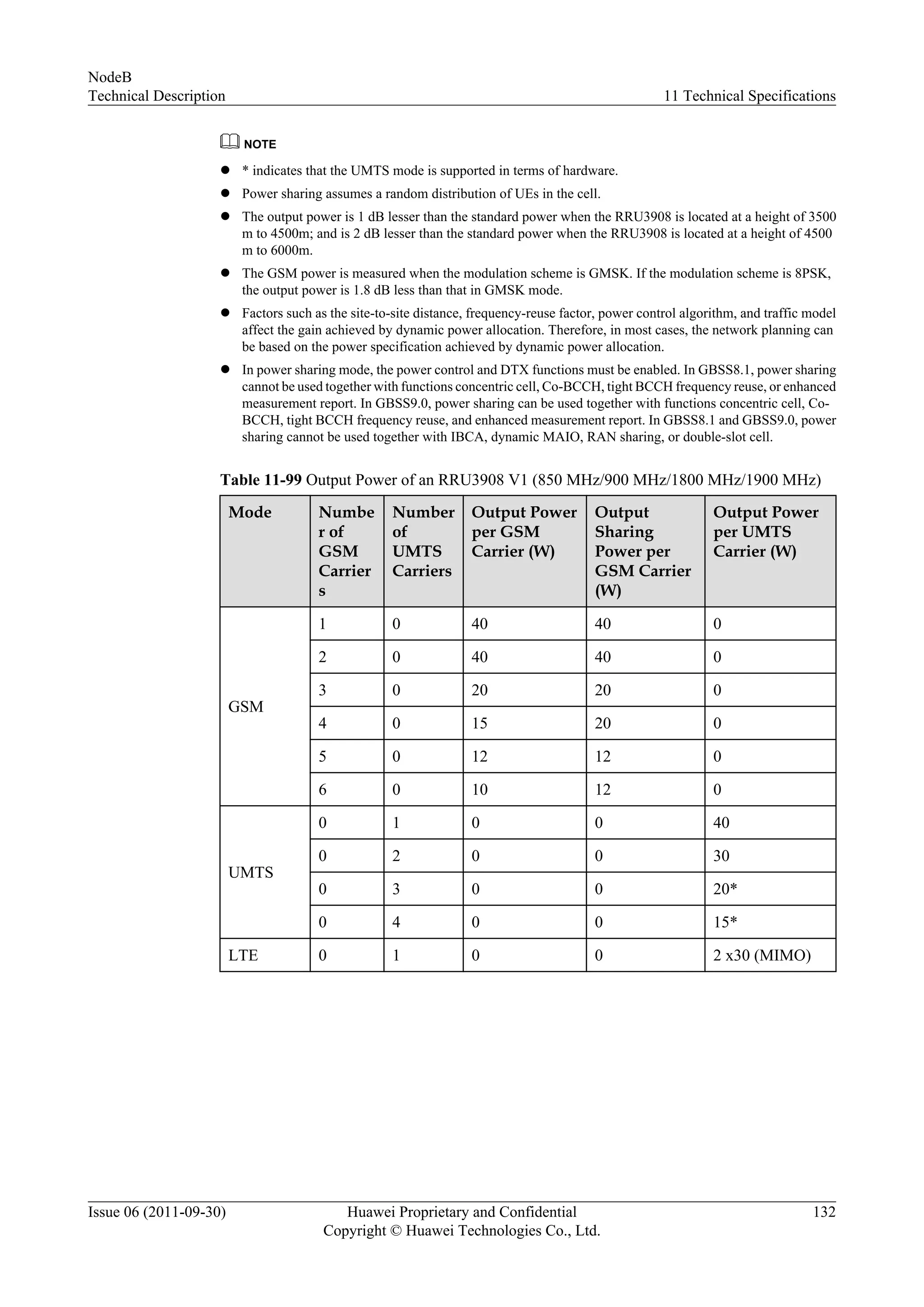
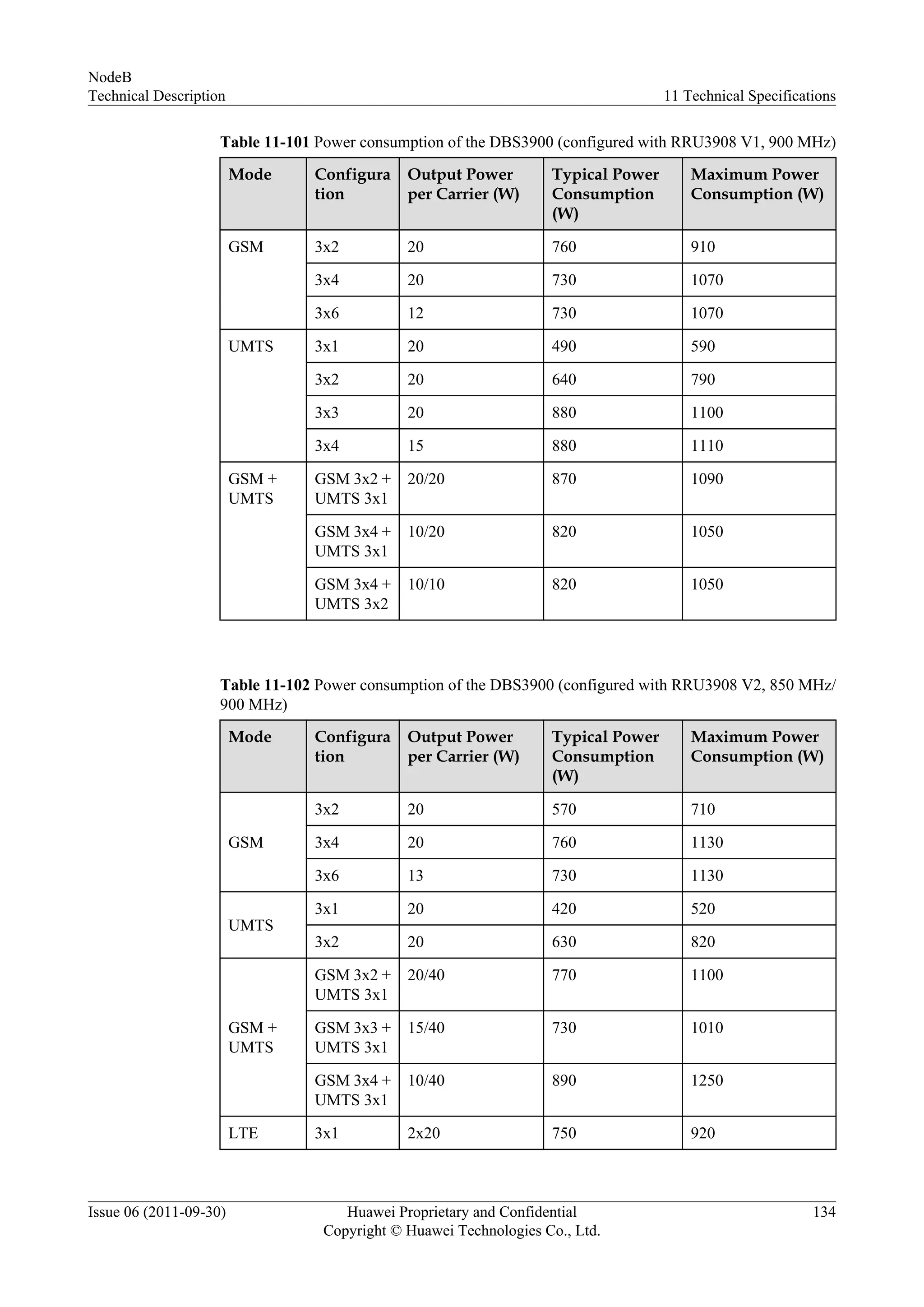
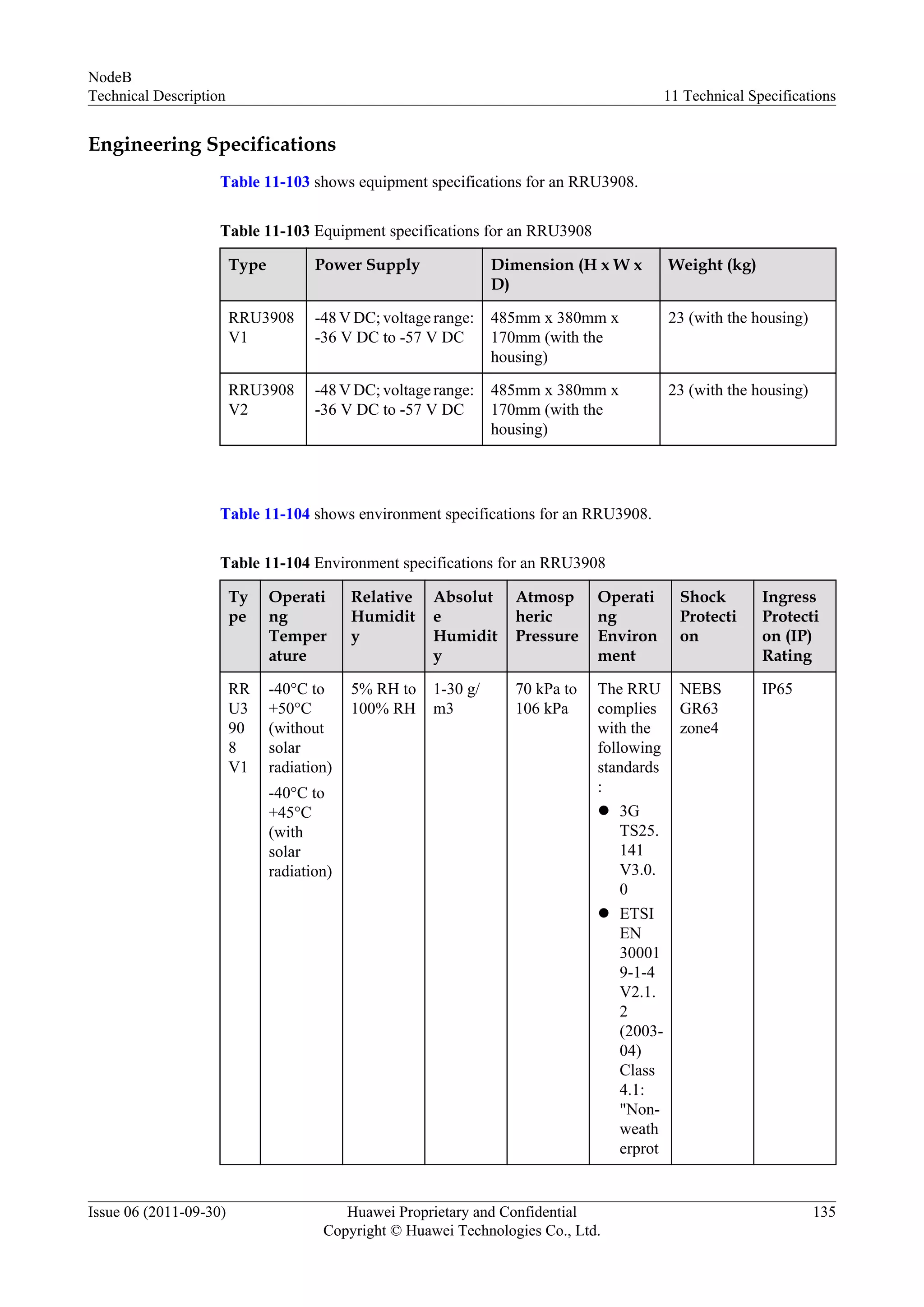
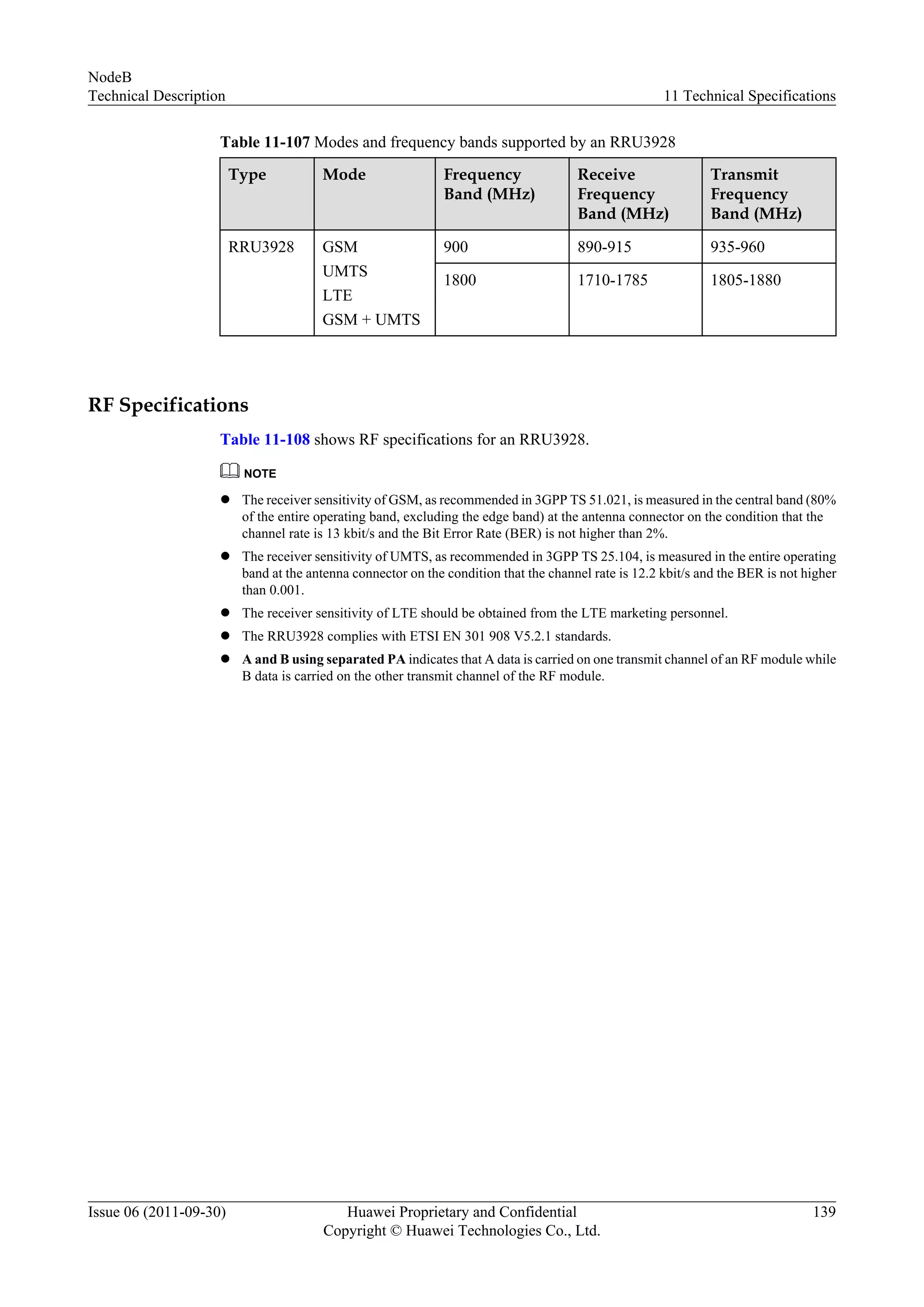
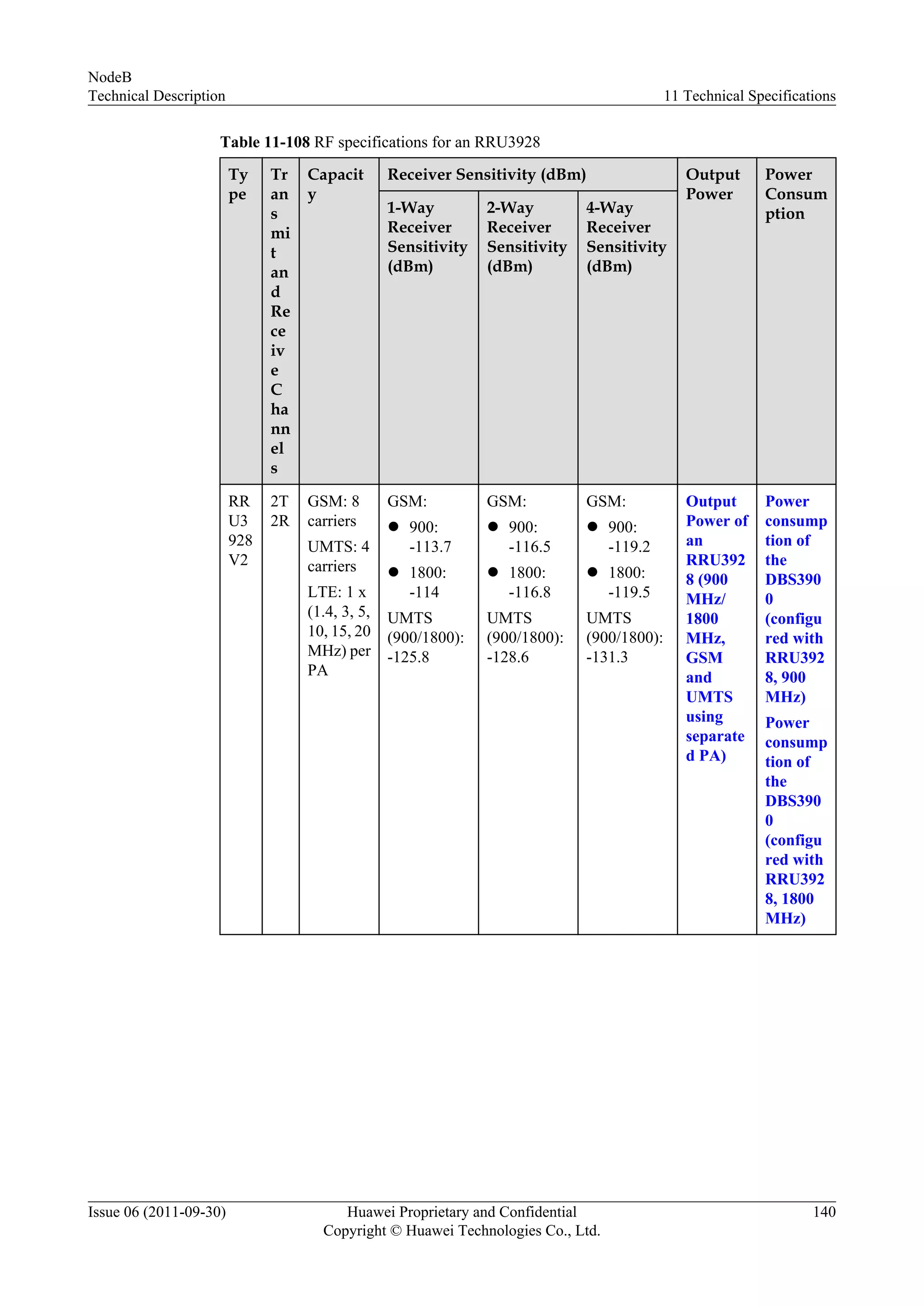
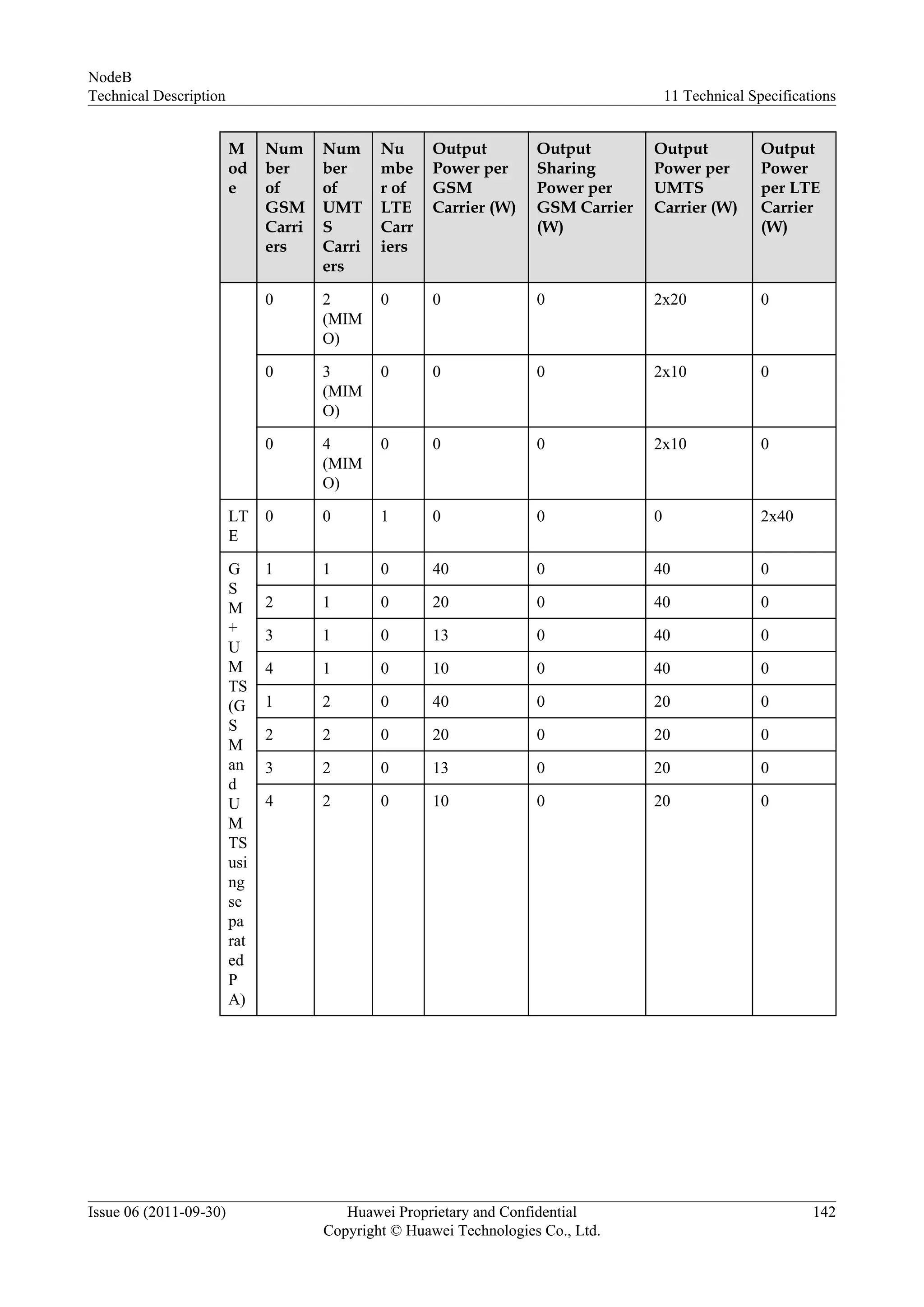
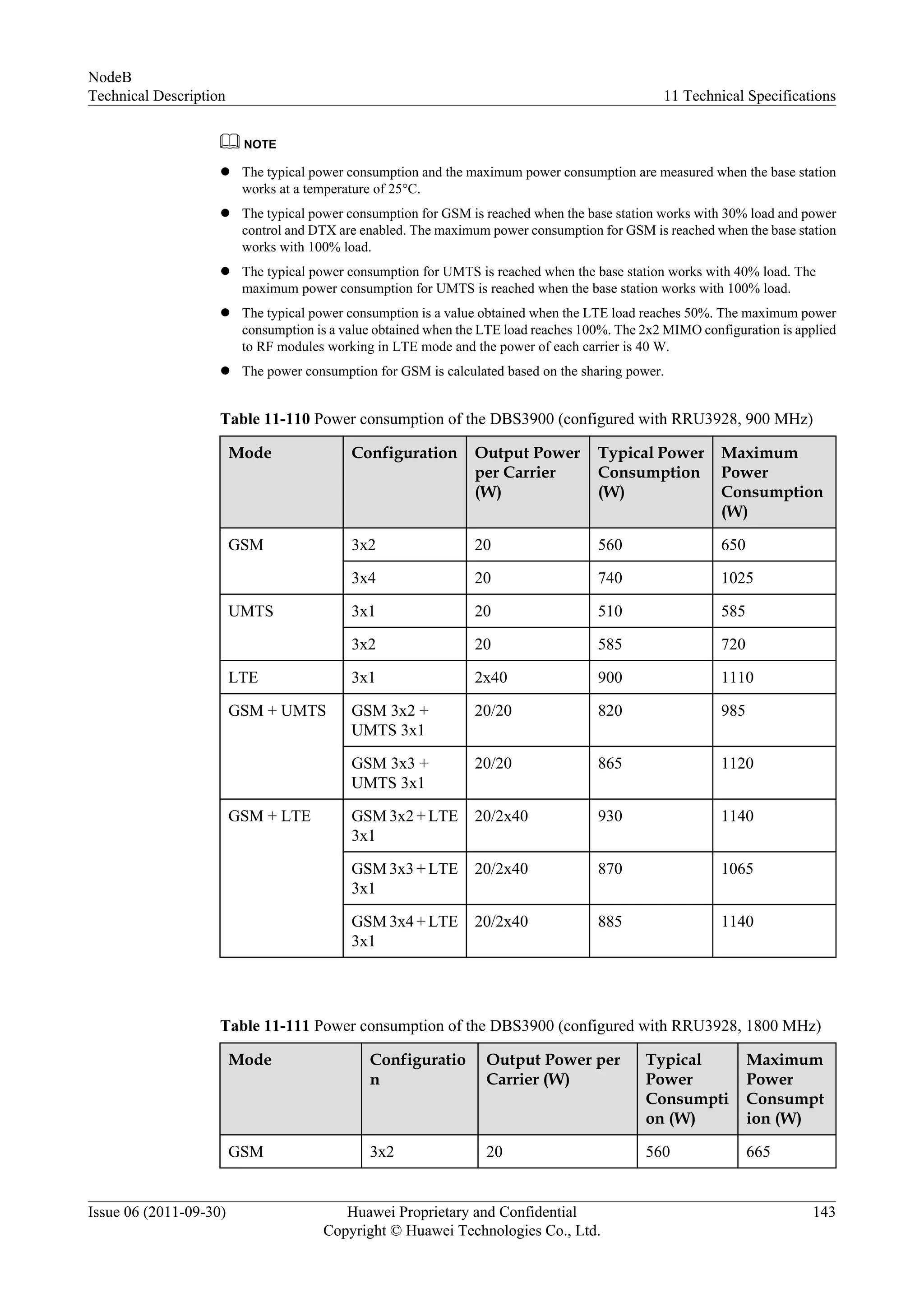
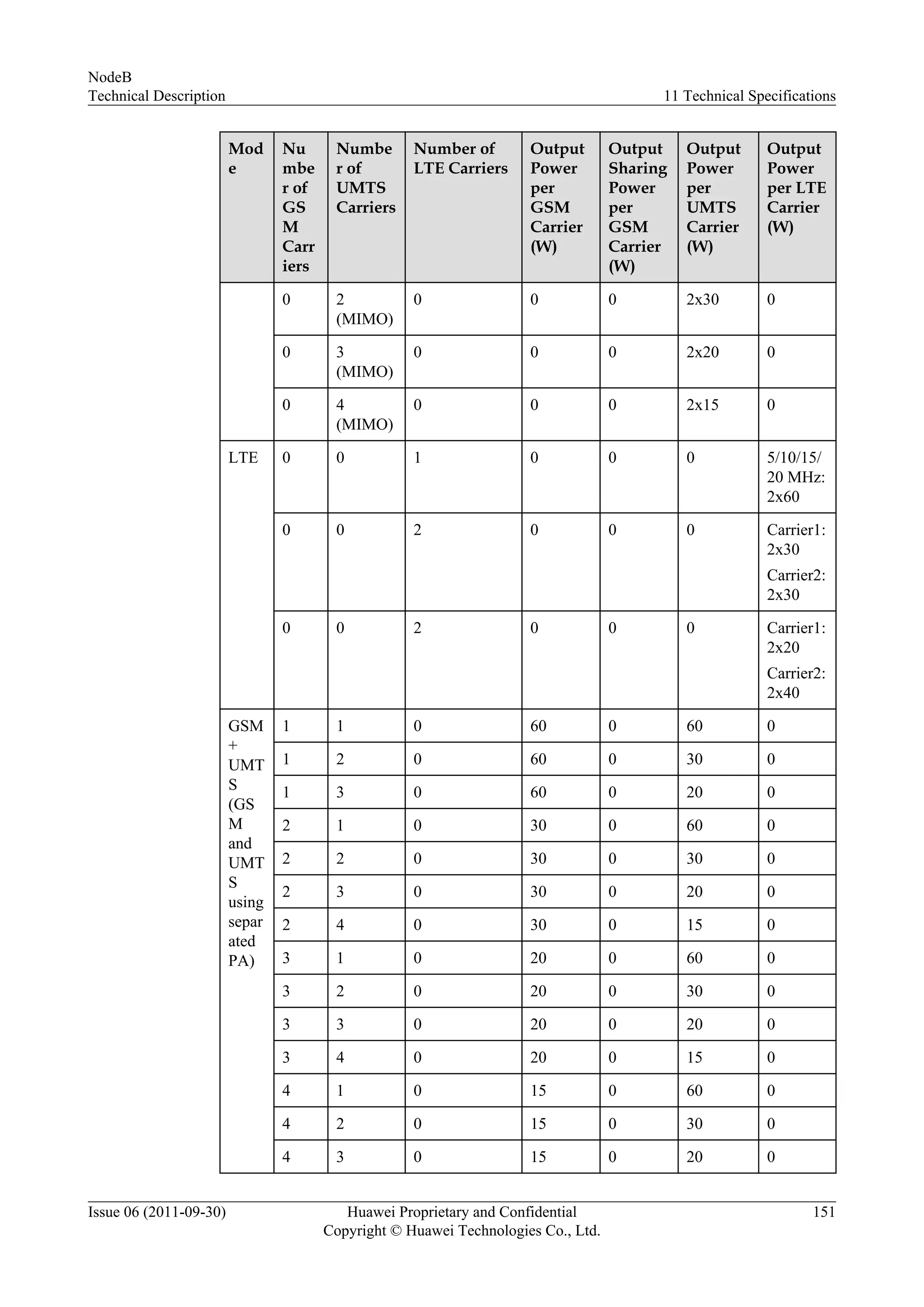
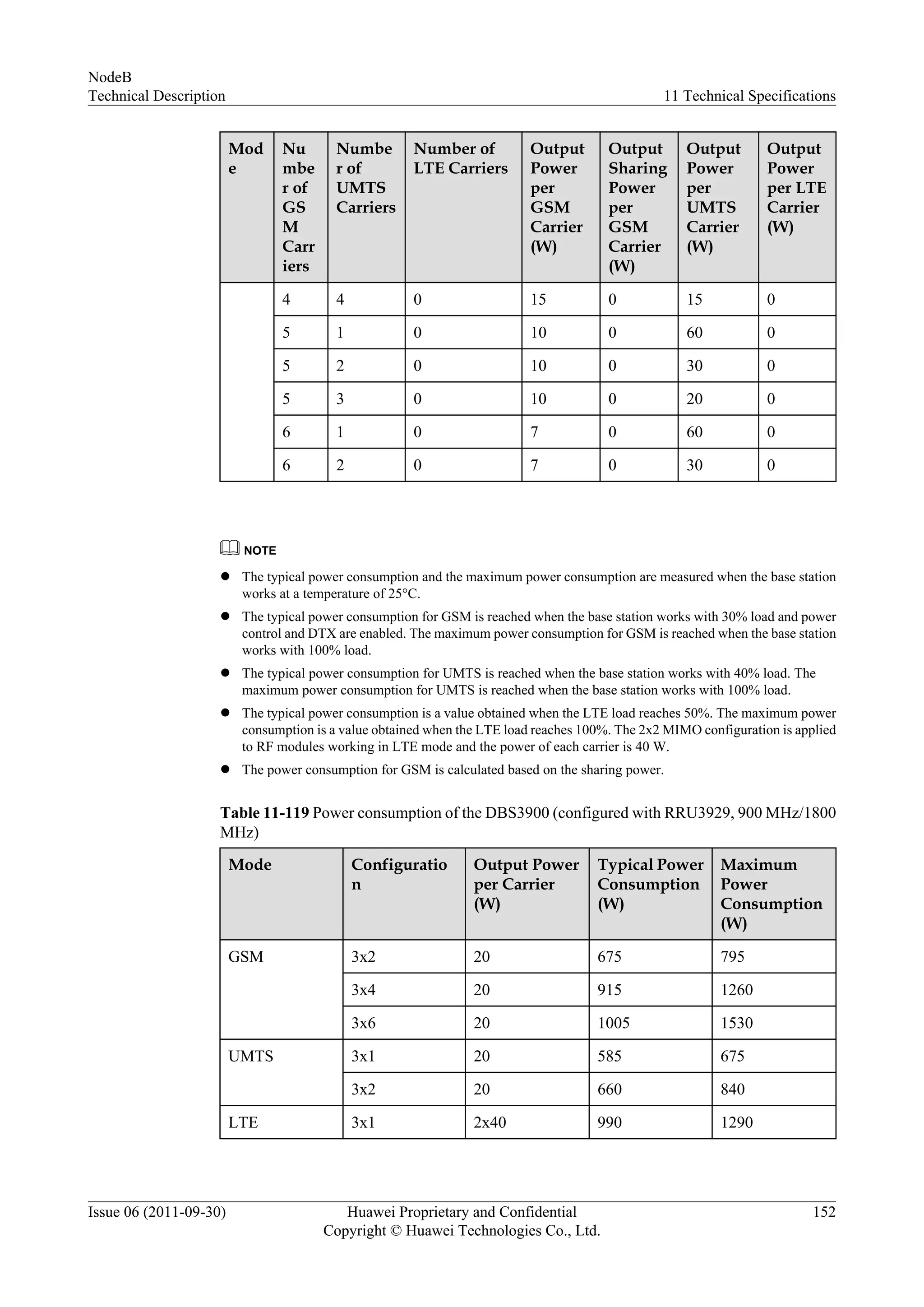
Details changes in NodeB documentation and overall architecture compliant with 3GPP standards. Technical details and specifications for RF modules and their operational capabilities.Detailed specifications for various RRU models including modes, frequencies and performance.
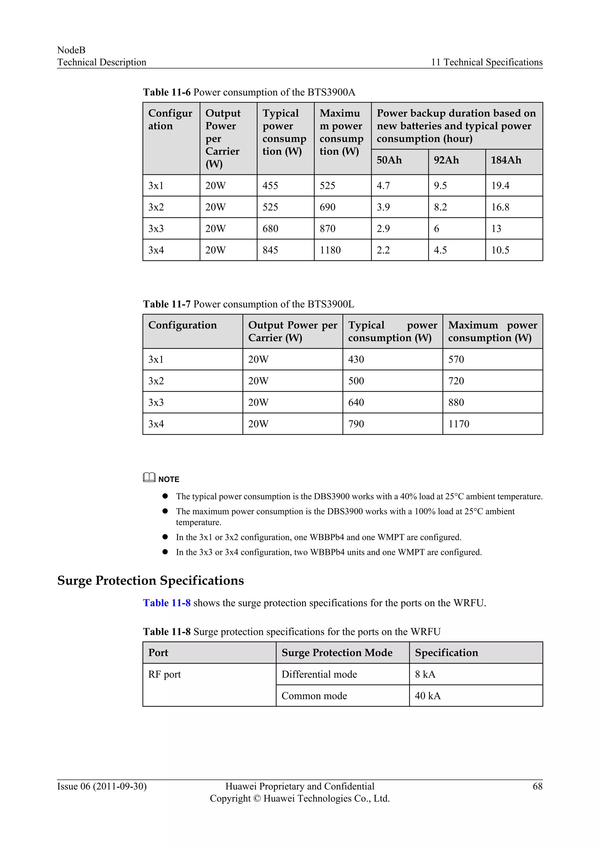
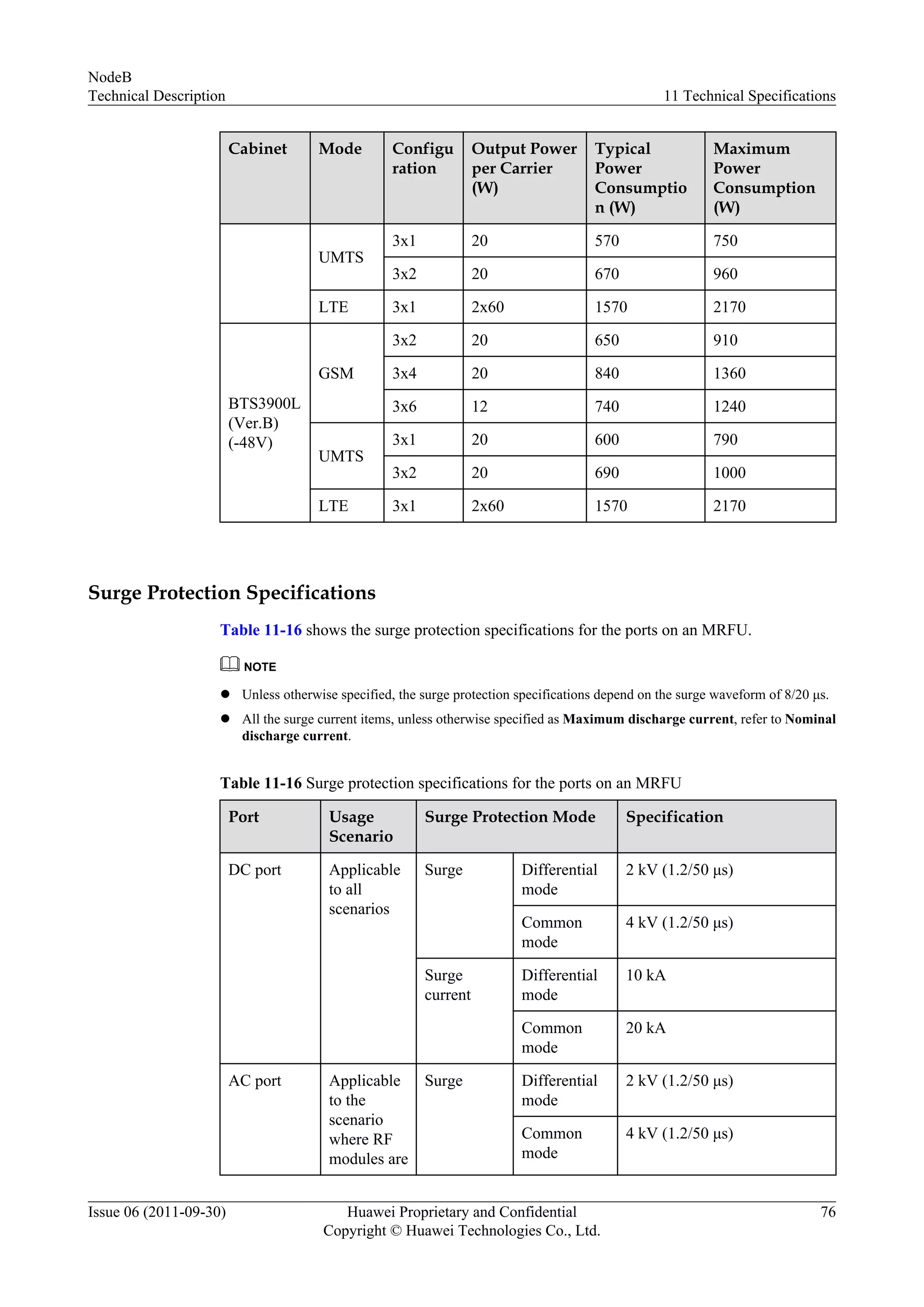
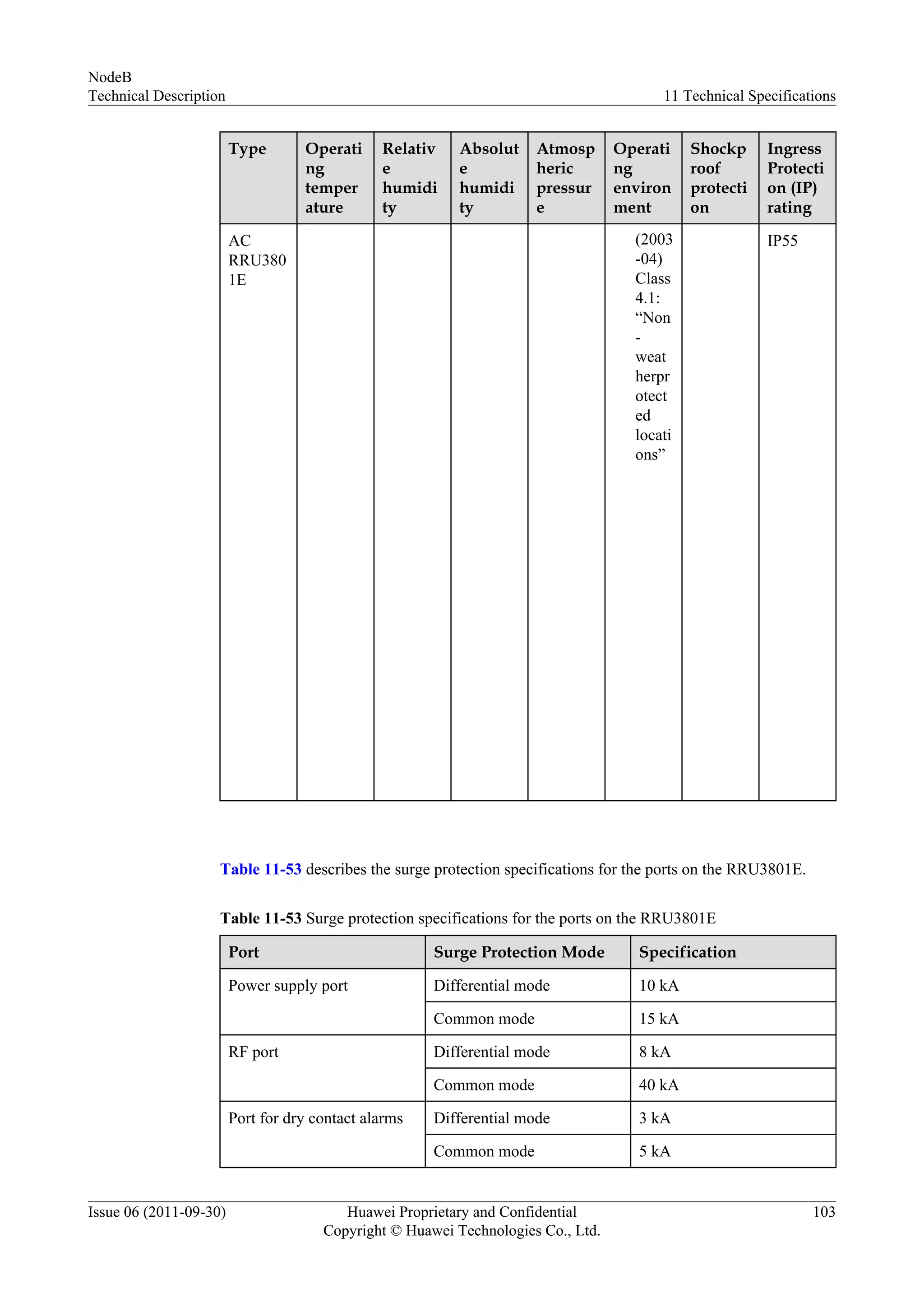
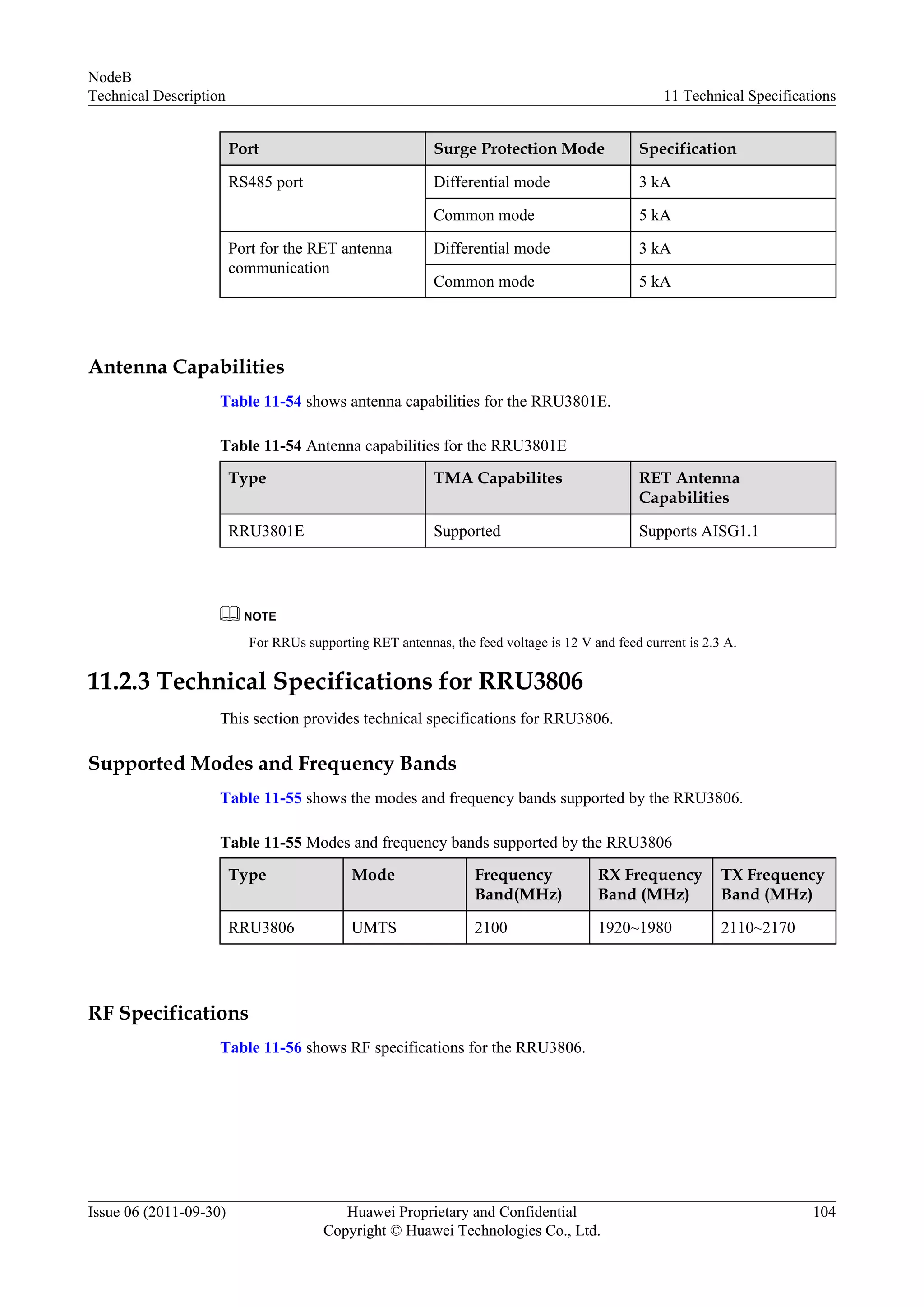
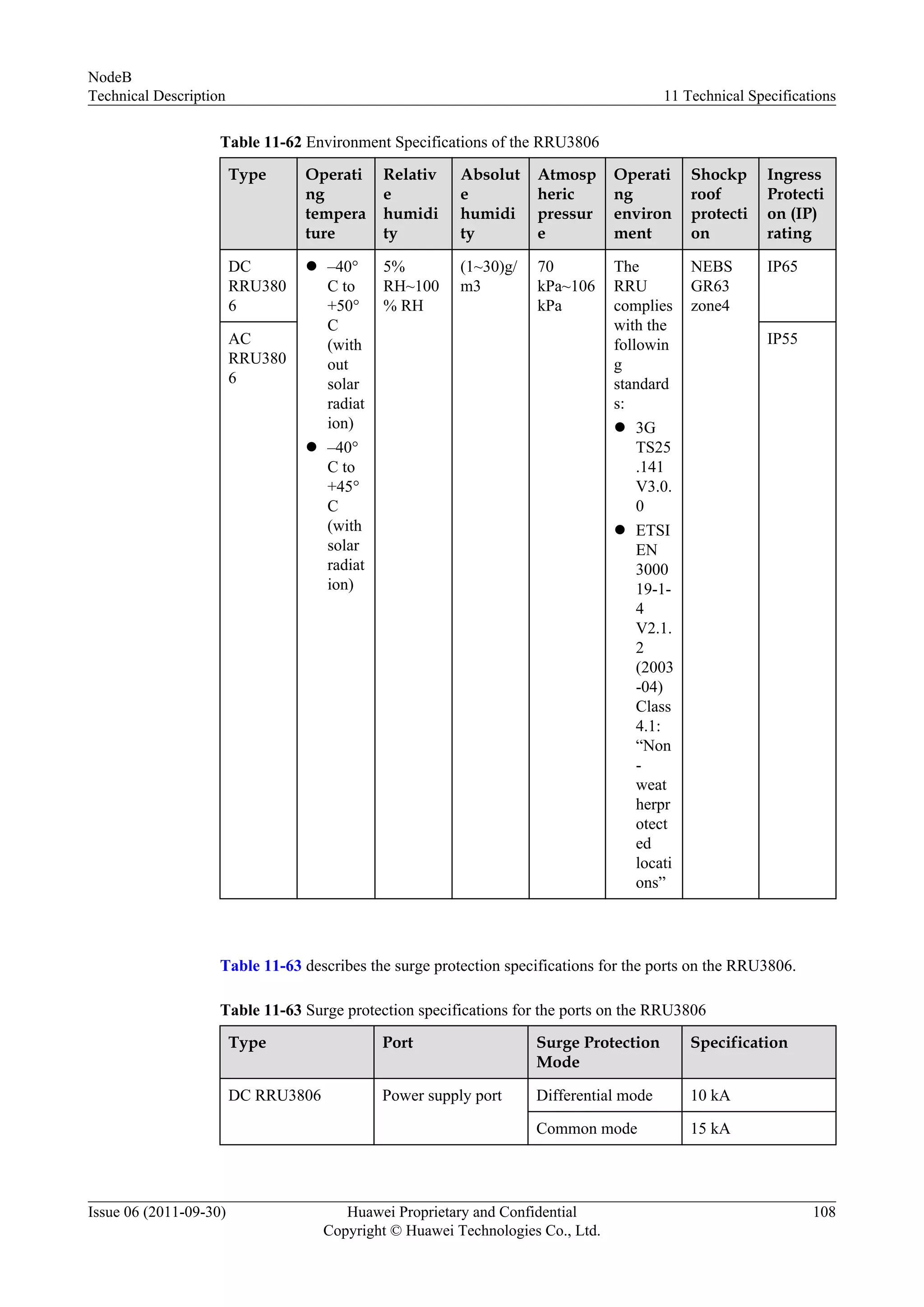
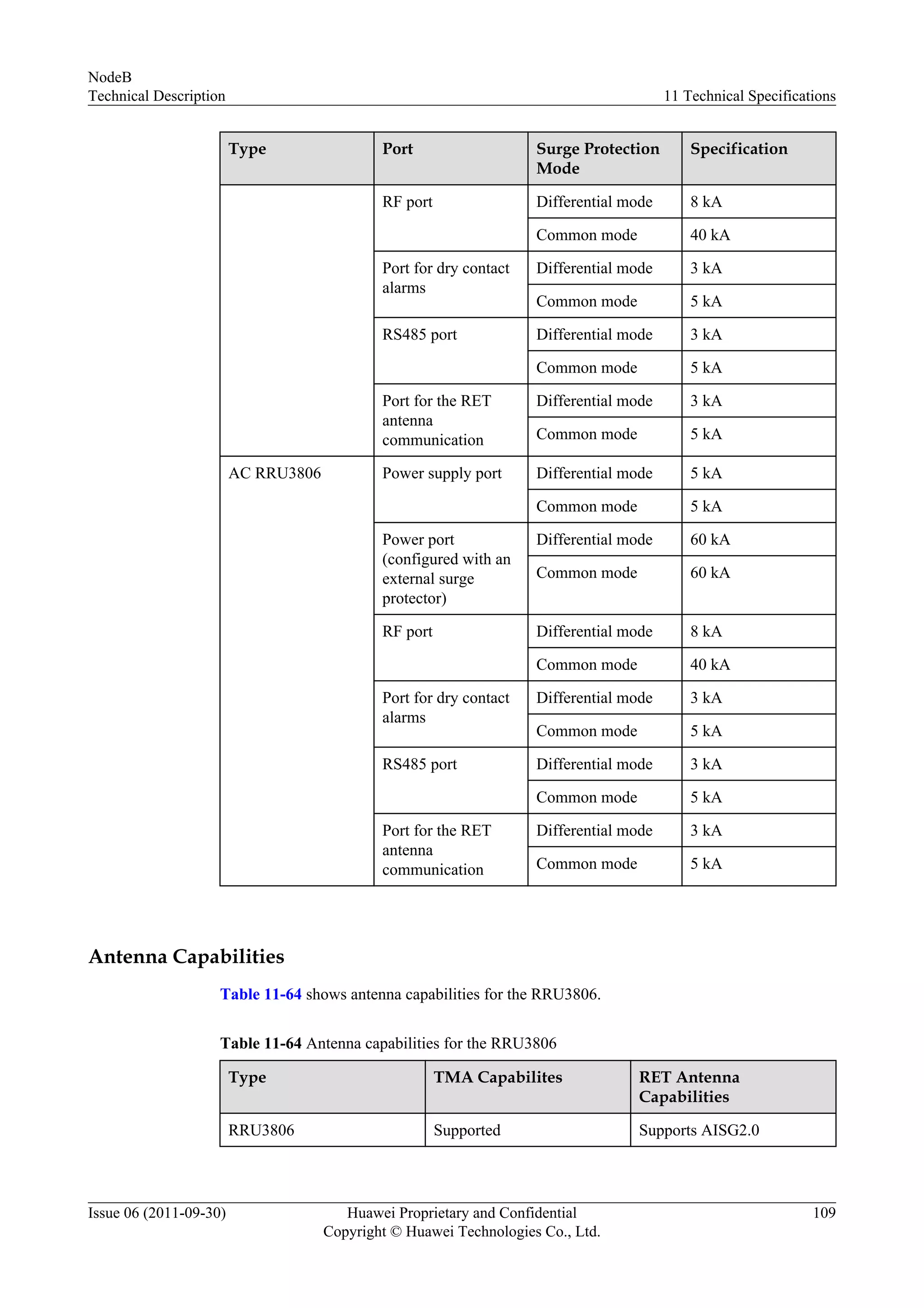
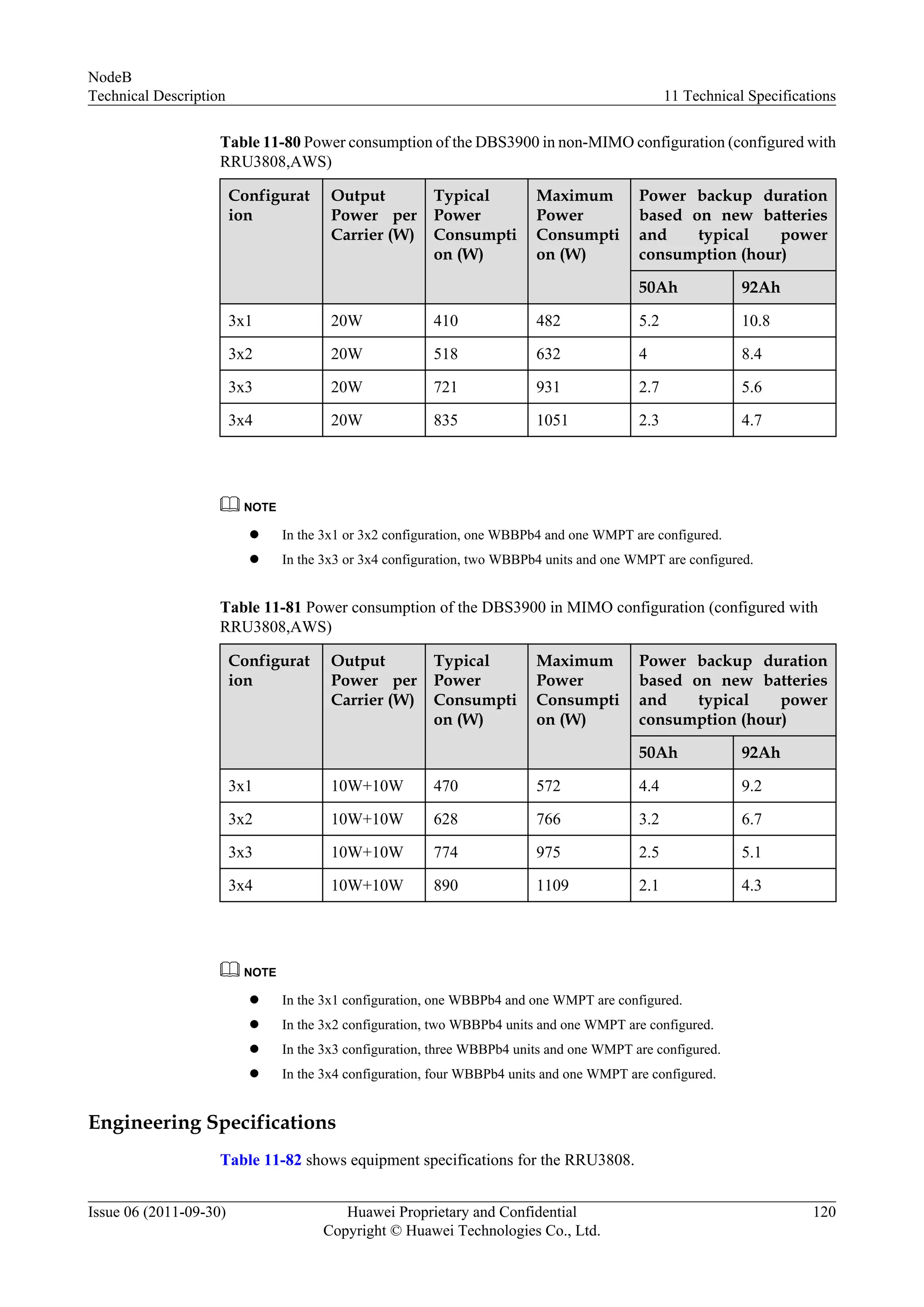
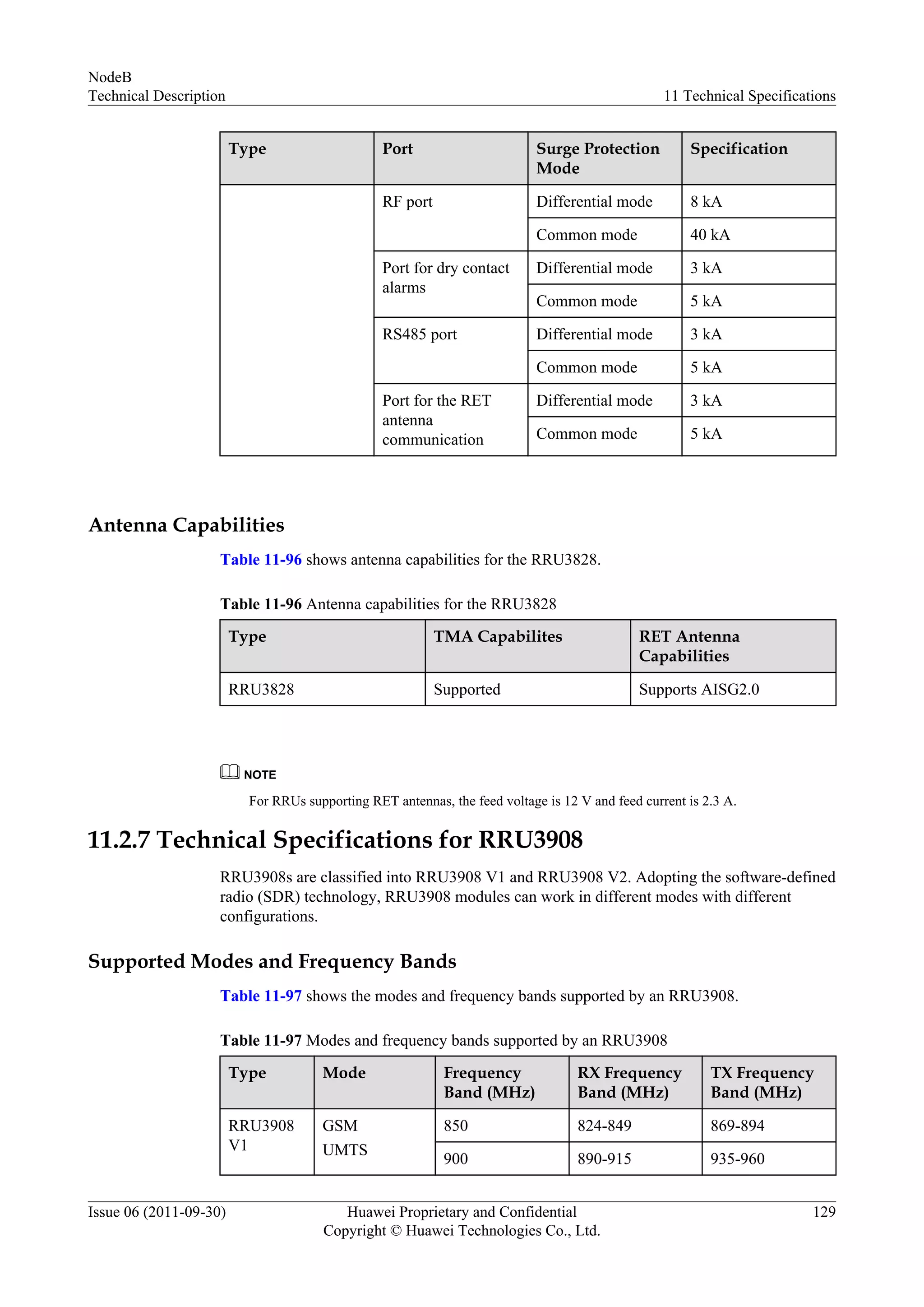
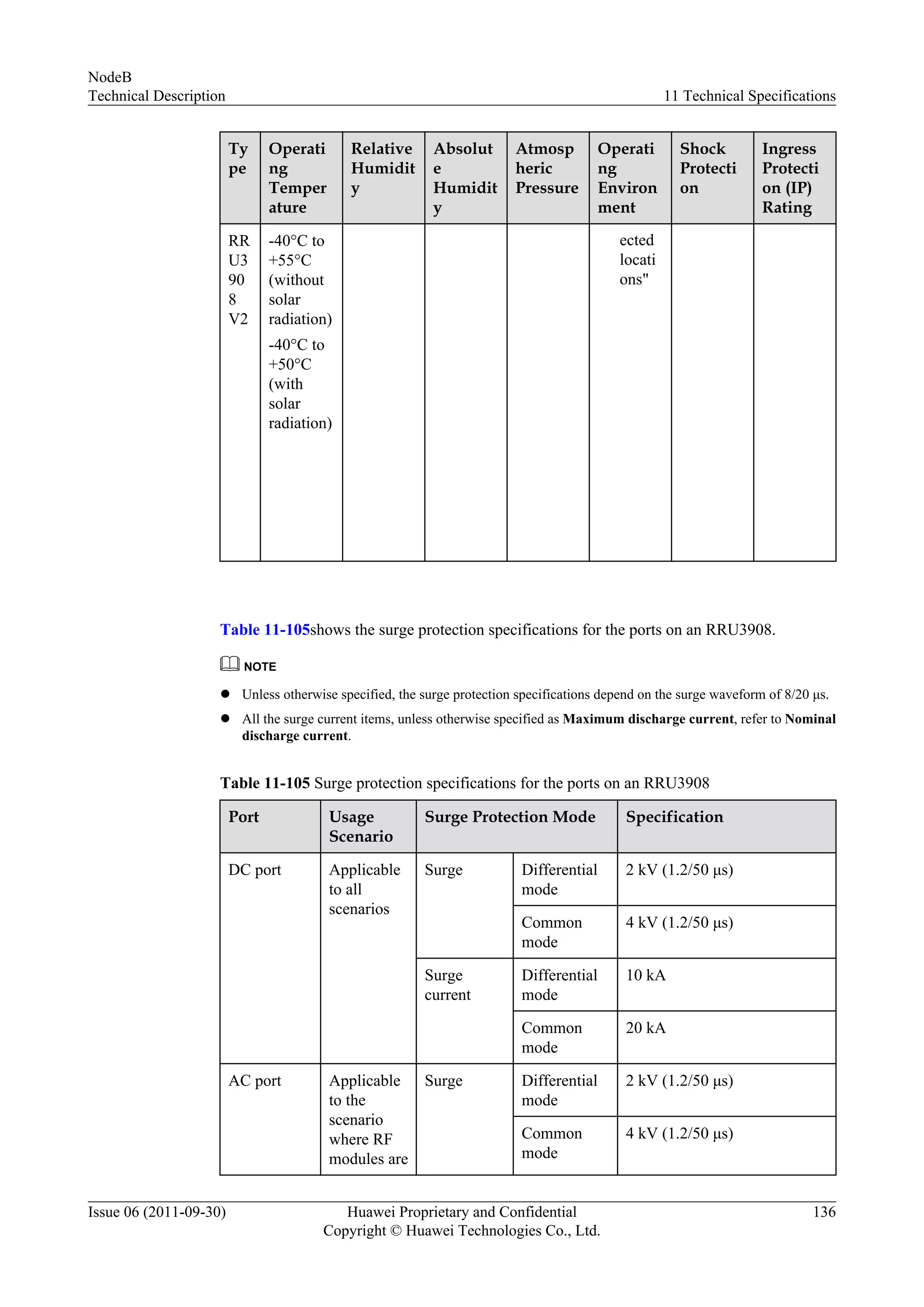
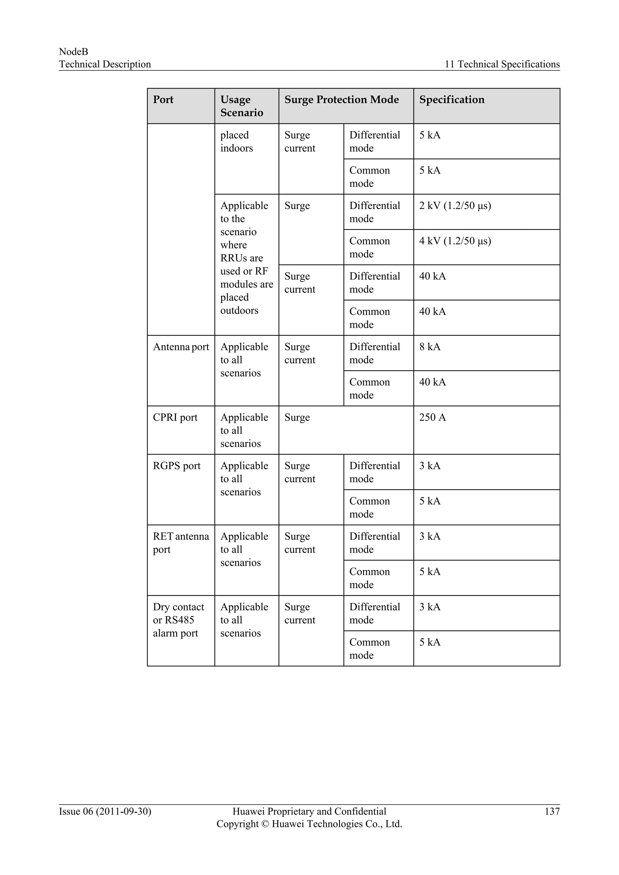
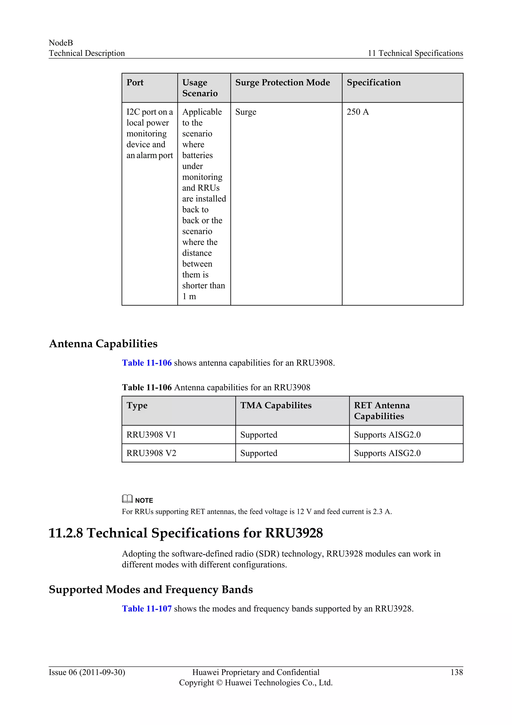
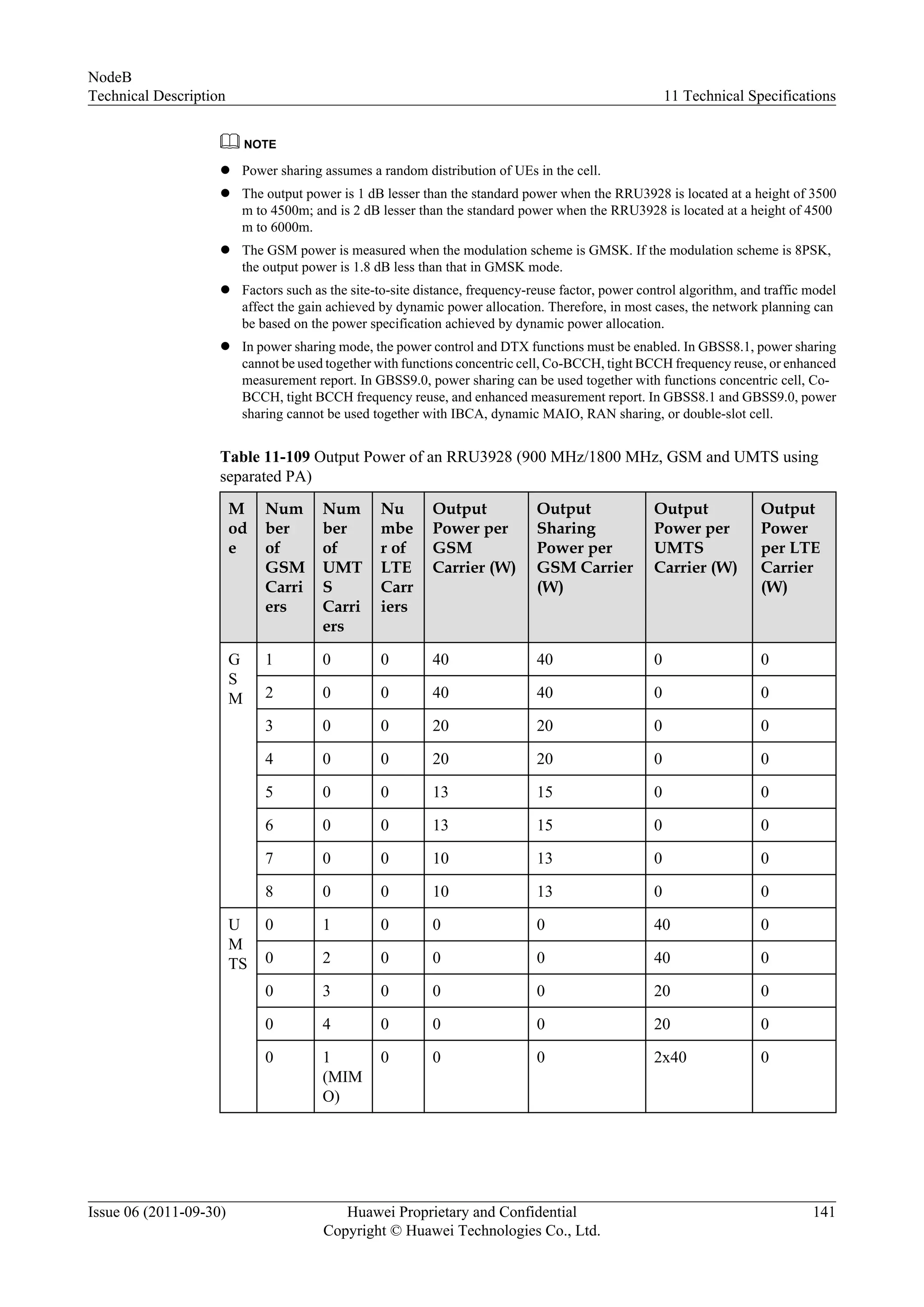
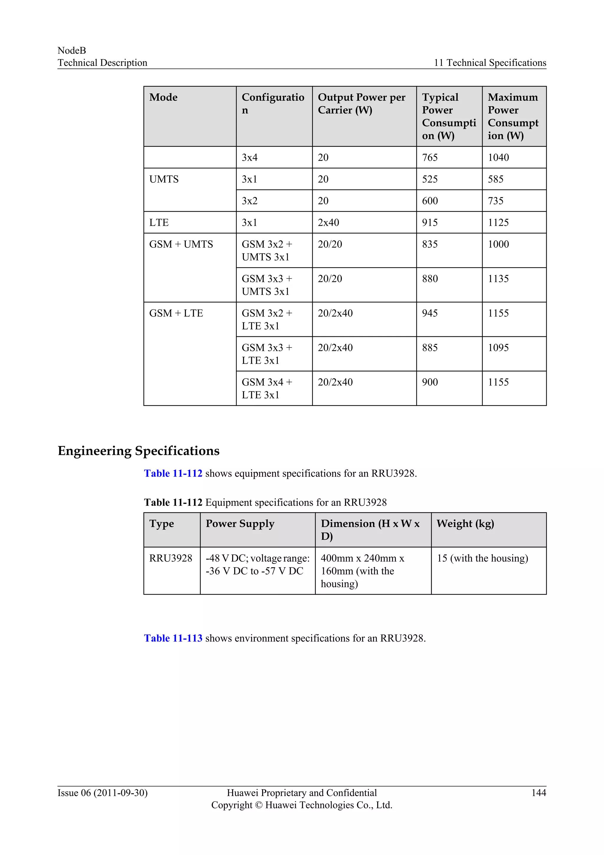
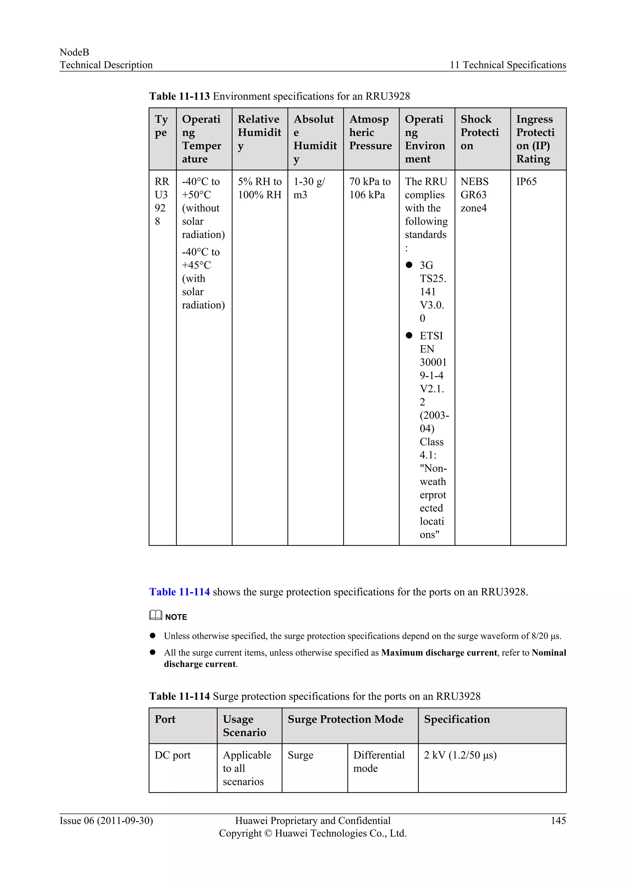
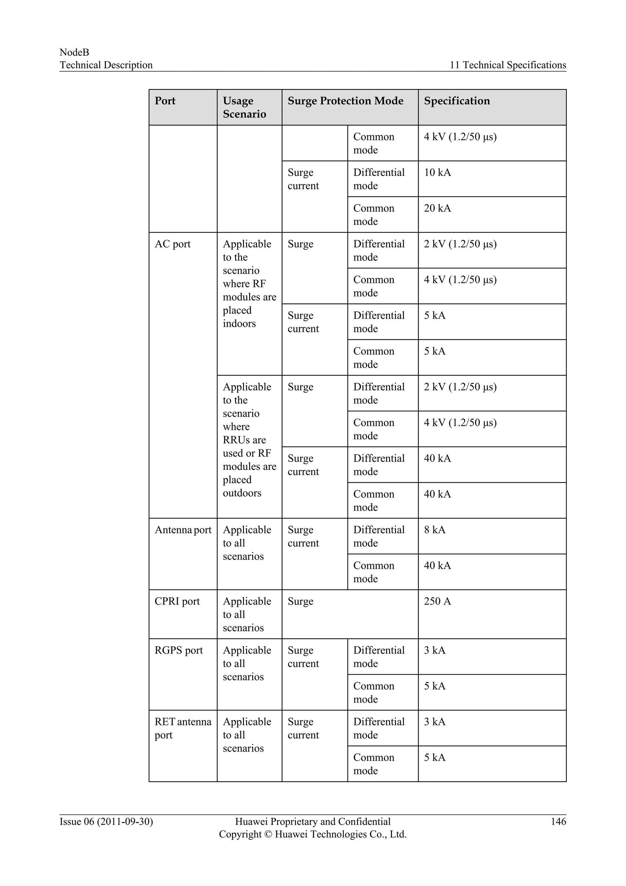
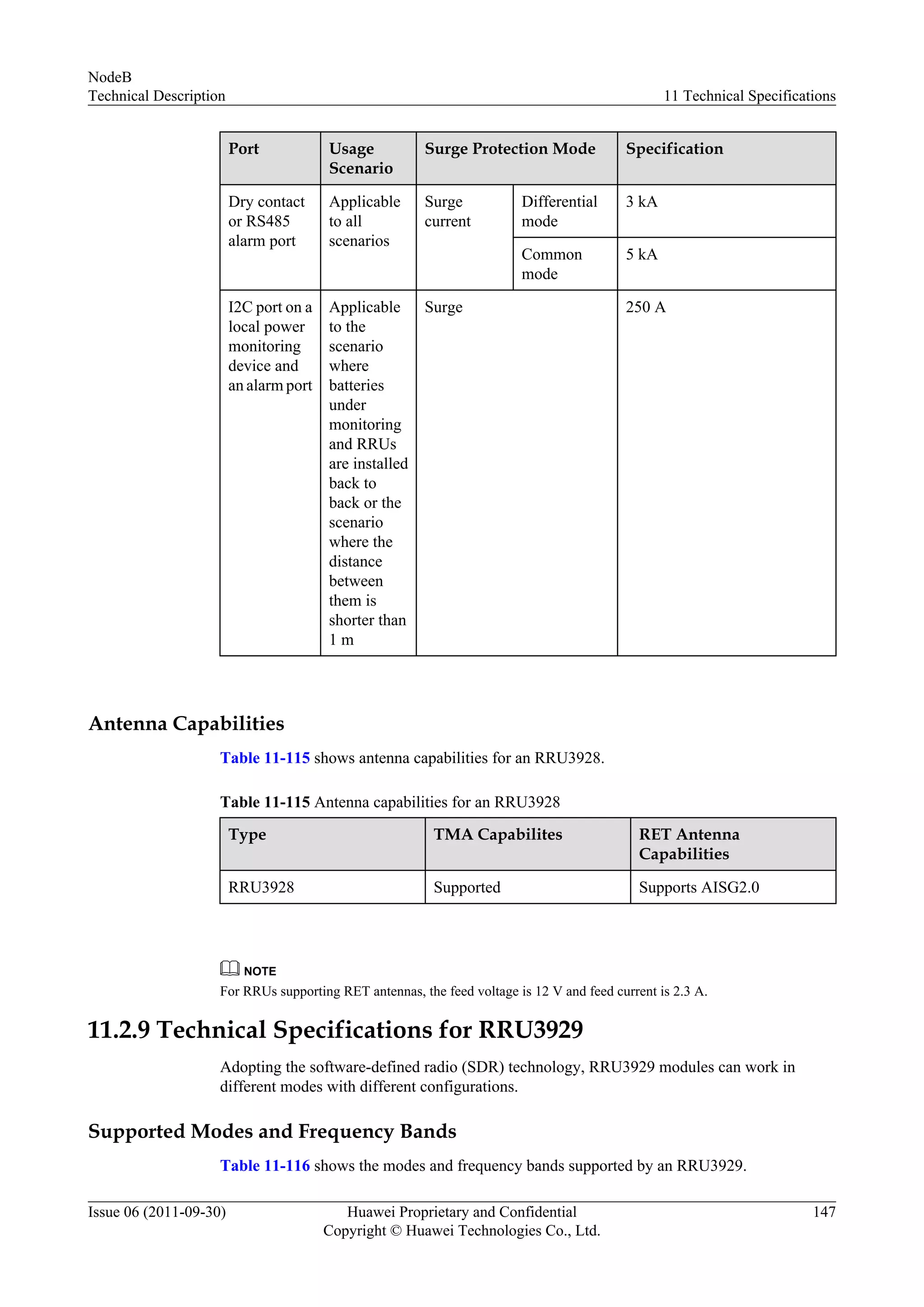
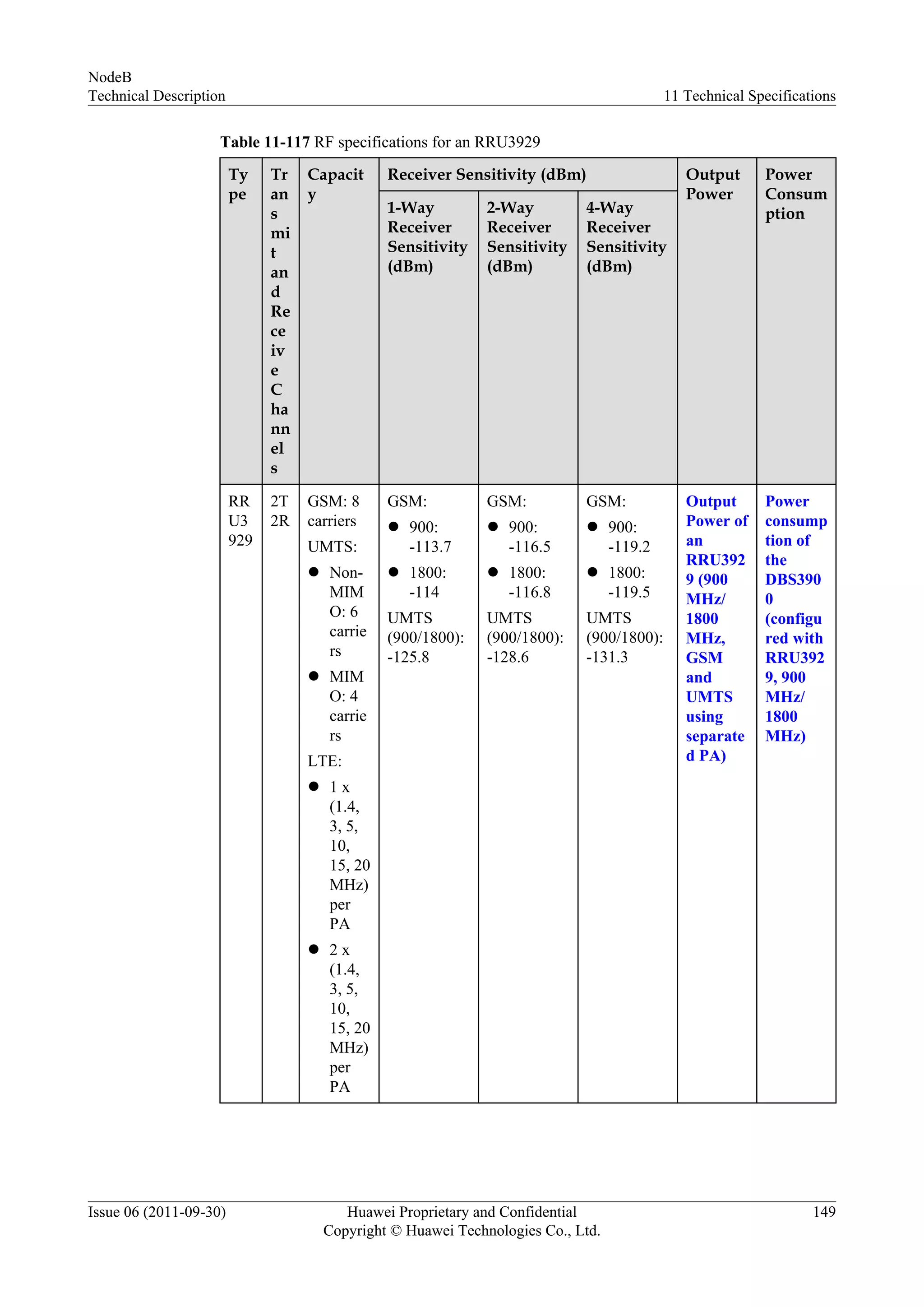
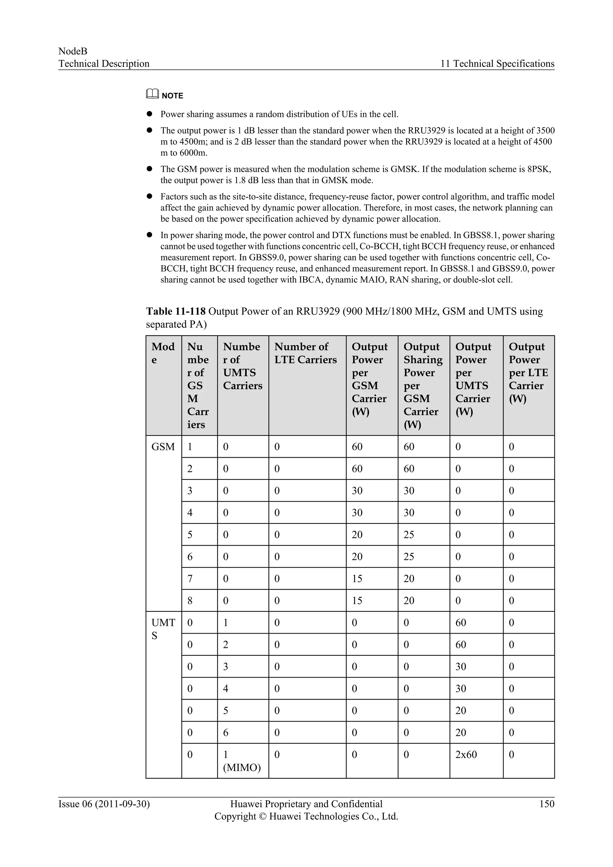
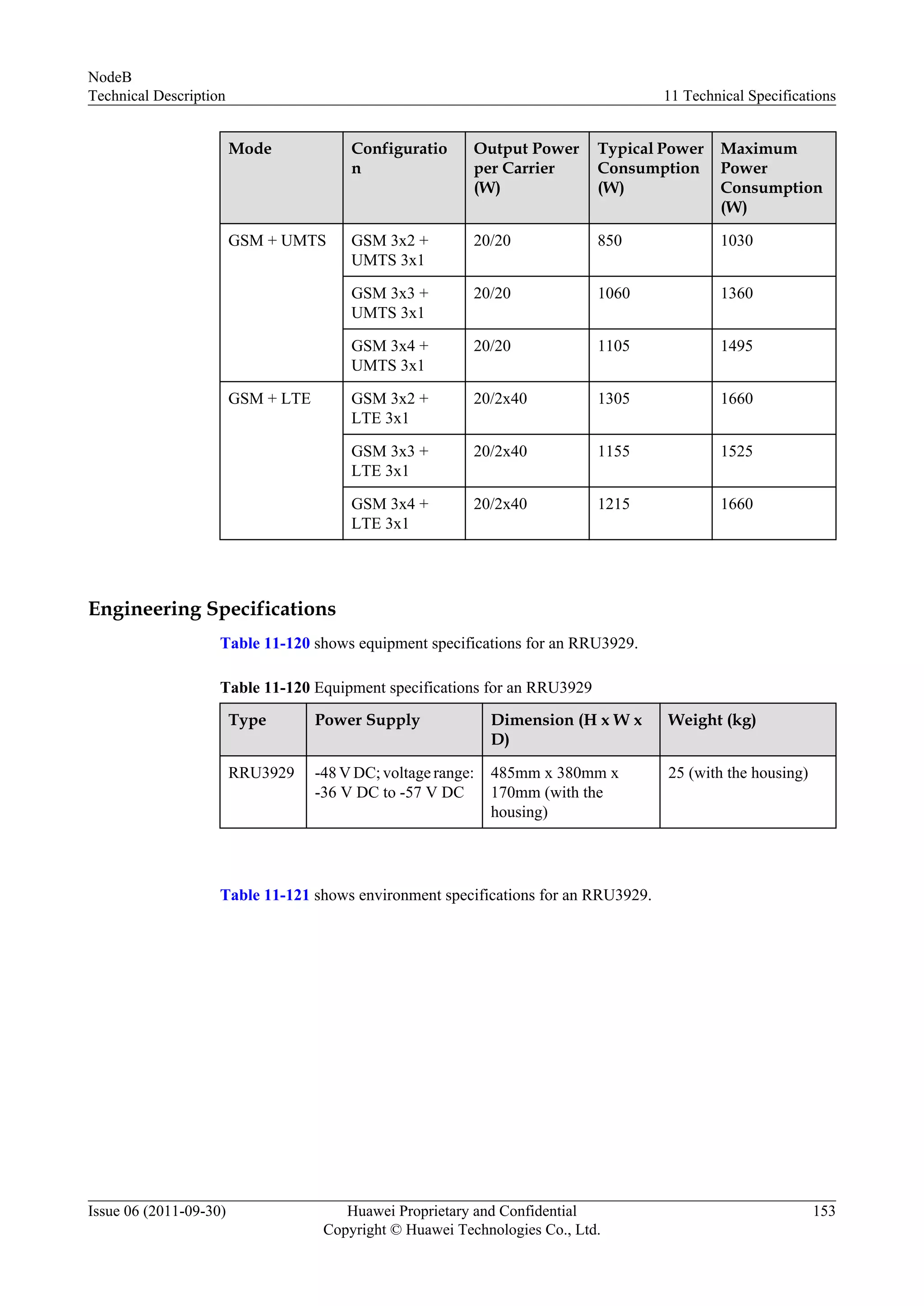
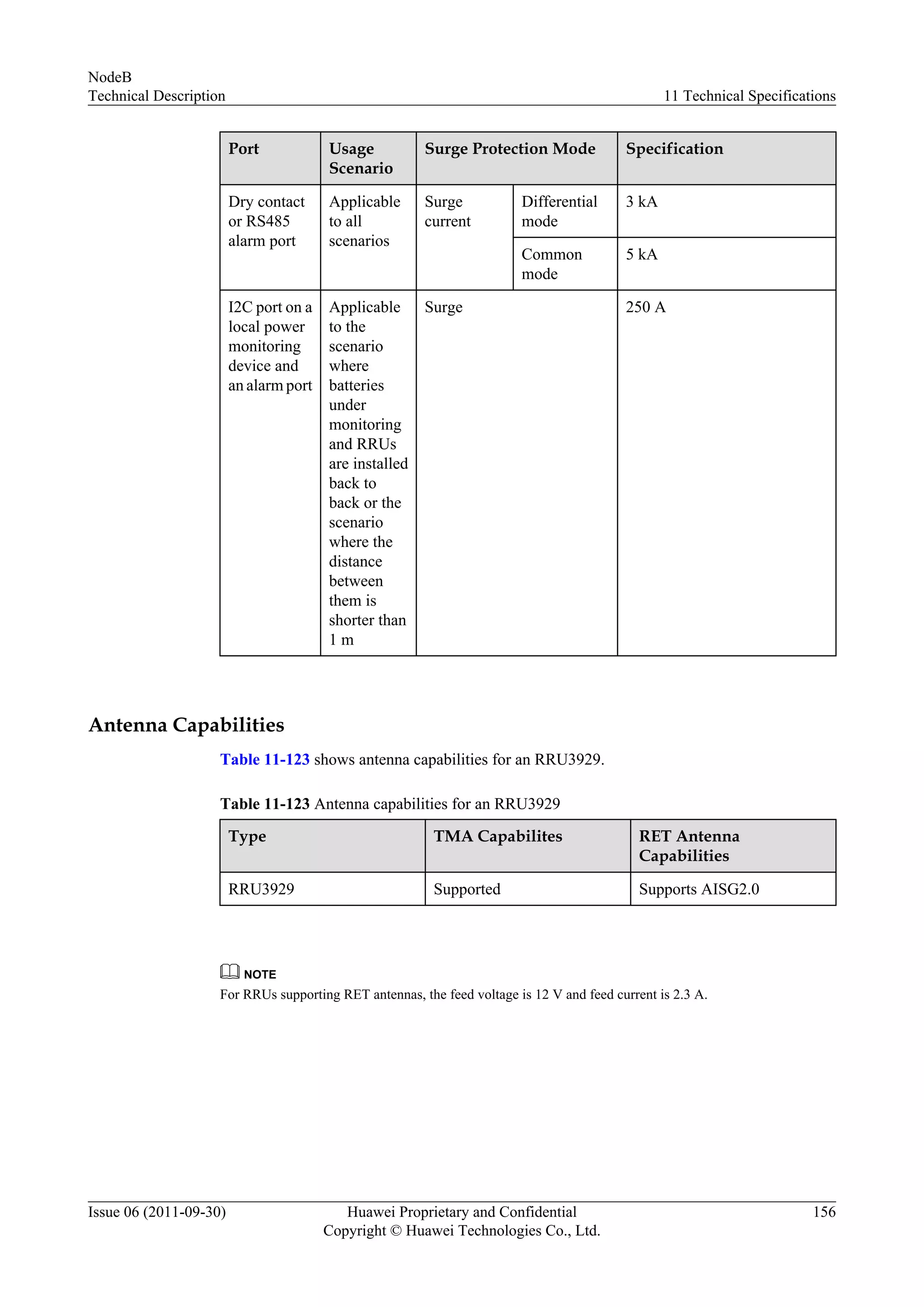
Specifications for RRU3928 and 3929, their configurations, and surge protection.
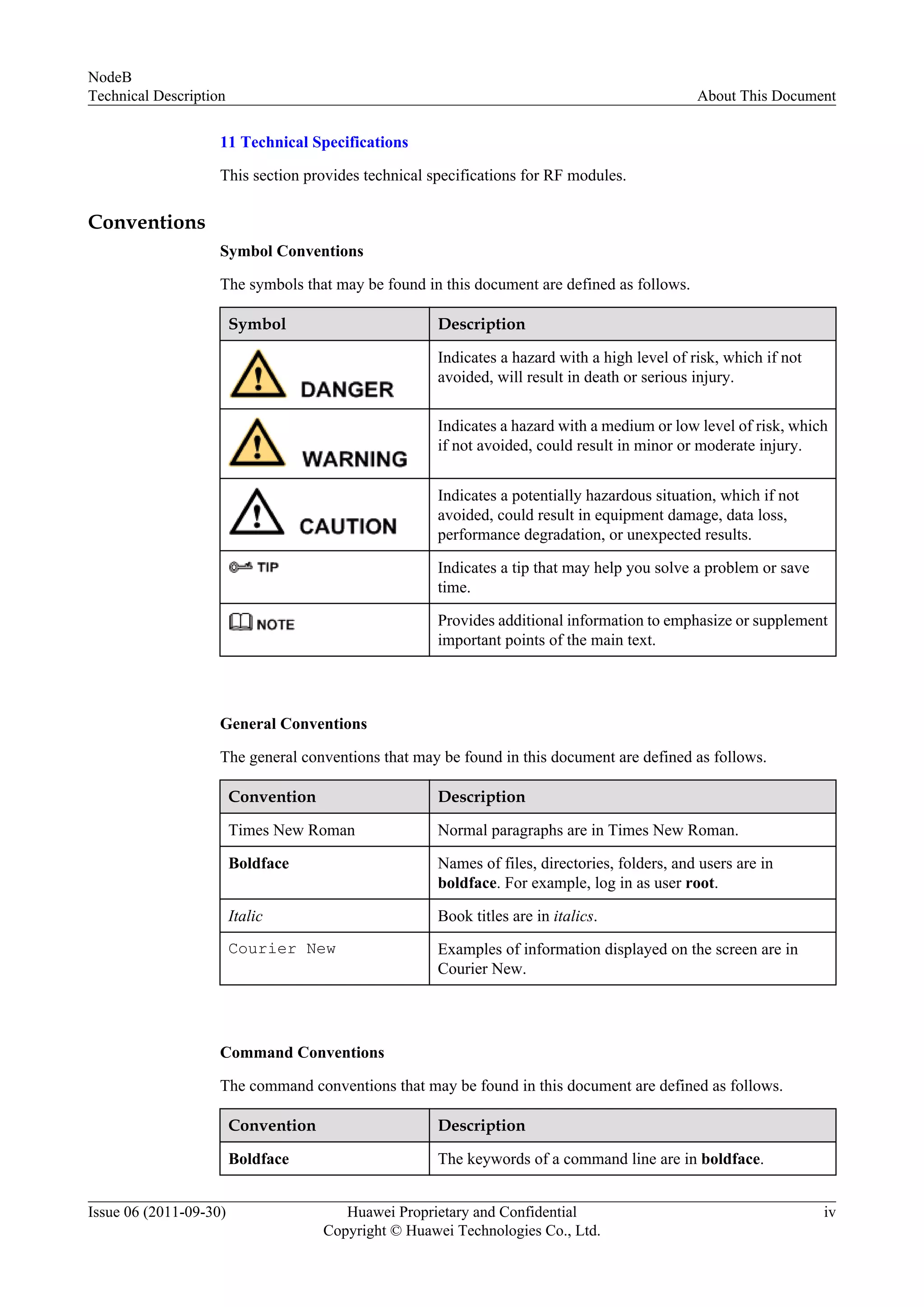
![Convention Description
Italic Command arguments are in italics.
[ ] Items (keywords or arguments) in brackets [ ] are optional.
{ x | y | ... } Optional items are grouped in braces and separated by
vertical bars. One item is selected.
[ x | y | ... ] Optional items are grouped in brackets and separated by
vertical bars. One item is selected or no item is selected.
{ x | y | ... }* Optional items are grouped in braces and separated by
vertical bars. A minimum of one item or a maximum of all
items can be selected.
[ x | y | ... ]* Optional items are grouped in brackets and separated by
vertical bars. Several items or no item can be selected.
GUI Conventions
The GUI conventions that may be found in this document are defined as follows.
Convention Description
Boldface Buttons, menus, parameters, tabs, window, and dialog titles
are in boldface. For example, click OK.
> Multi-level menus are in boldface and separated by the ">"
signs. For example, choose File > Create > Folder.
Keyboard Operations
The keyboard operations that may be found in this document are defined as follows.
Format Description
Key Press the key. For example, press Enter and press Tab.
Key 1+Key 2 Press the keys concurrently. For example, pressing Ctrl+Alt
+A means the three keys should be pressed concurrently.
Key 1, Key 2 Press the keys in turn. For example, pressing Alt, A means
the two keys should be pressed in turn.
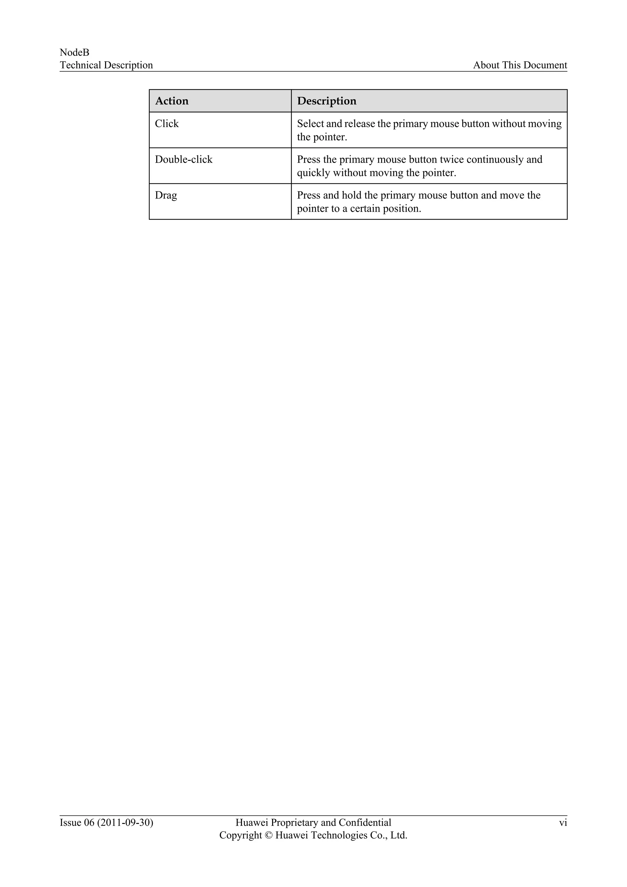
Mouse Operations
The mouse operations that may be found in this document are defined as follows.
NodeB
Technical Description About This Document
Issue 06 (2011-09-30) Huawei Proprietary and Confidential
Copyright © Huawei Technologies Co., Ltd.
v](https://image.slidesharecdn.com/huaweinodeb-technical-description-160717202639/75/Huawei-node-b-technical-description-6-2048.jpg)


![Nemo outdoor 6_training_aug2011 [compatibility mode]](https://cdn.slidesharecdn.com/ss_thumbnails/nemooutdoor6trainingaug2011compatibilitymode-130826015745-phpapp02-thumbnail.jpg?width=640&height=640&fit=bounds)


![Vibe Coding vs. Spec-Driven Development [Free Meetup]](https://cdn.slidesharecdn.com/ss_thumbnails/vibecodingvsspecdrivendevelopment-251209105622-43f455e7-thumbnail.jpg?width=640&height=640&fit=bounds)


