1. 16
Reinforced Concrete Design
One-Way Slabs
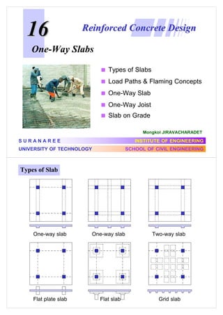
Types of Slabs
Load Paths & Flaming Concepts
One-Way Slab
One-Way Joist
Slab on Grade
Mongkol JIRAVACHARADET
SURANAREE
INSTITUTE OF ENGINEERING
UNIVERSITY OF TECHNOLOGY
SCHOOL OF CIVIL ENGINEERING
Types of Slab
One-way slab
Flat plate slab
One-way slab
Flat slab
Two-way slab
Grid slab
2. Load Path / Framing Possibilities
Ln = 3.2 m
Ln = 4.4 m
Ln = 3.6 m
Ln = 8.2 m
Think we’ll need some additional framing members???
Framing Concepts
Let’s use a simple example
for our discussion…
Column spacing 8 m c-c
Think about relating it to your
design project.
Plan
3. Framing Concepts
We can first assume that
we’ll have major girders
running in one direction
in our one-way system
Framing Concepts
We can first assume that
we’ll have major girders
running in one direction
in our one-way system
If we span between girders
with our slab, then we have
a load path, but if the spans
are too long…
4. Framing Concepts
We will need to shorten up
the span with additional beams
But we need to support the
load from these new beams,
so we will need additional
supporting members
Framing Concepts
Now let’s go back through with
a slightly different load path.
We again assume that we’ll
have major girders running in
one direction in our one-way
system.
This time, let’s think about
shortening up the slab span by
running beams into our girders.
Our one-way slab will transfer our load to the beams.
5. Two Load Path Options
Framing Concepts - Considerations
For your structure:
Look for a “natural” load path
Identify which column lines are best suited to having
major framing members (i.e. girders)
Assume walls are not there for structural support, but
consider that the may help you in construction (forming)
6. Example
Condo Floor Plan
ก
One-Way Slab :
ก
ก
: F
S
(L) >
F
F
S
L
S
t
L
Simple supports
on two long
edges only
S
(S)
S
การแอนตัวเกิดขึ้นบนดานสั้น
8. ก
ก
˂ ก ก
ก
F
ก
As
F
(
ก
ก
ก F )
Ag : As/Ag
1m
RB24 (fy = 2,400 ksc) . . . . . . . . . . . . . . 0.0025
t
DB30 (fy = 3,000 ksc) . . . . . . . . . . . . . . 0.0020
Ag = b × t = 100 t
DB40 (fy = 4,000 ksc) . . . . . . . . . . . . . . 0.0018
DB (fy > 4,000 ksc) . . . . . . . . . . . . . . . . 0.0018 × 4,000 ≥ 0.0014
fy
Spacing ≤ 3 t ≤ 45 cm
Main Steel (short direction):
As ≥ ∅ 6 mm
Max. Spacing ≤ 3 t ≤ 45 cm
Min. Spacing ≥ f main steel ≥ 4/3 max agg. ≥ 2.5 cm
F
9.1 ก
ก
S1
ก
F ก 50 ก.ก./ .2 ก
fy = 2,400 ก.ก./ .2
ก F
300 ก.ก./ .2 WSD
F f c = 210 ก.ก./ .2
F
1)
F
F
S1
F
S2
F
fy = 2,400 ksc
0.4 +
2,400
= 0.74
7,000
t min = 0.74 ×
S1
2.7 m
ก
tmin = L/24
270
= 8.3 cm
24
t = 10 cm
ก
ก
ก
= 0.1 x 2,400 = 240 kg/m2
= 50 kg/m2
= 300 kg/m2
9. ก
F
= 240 + 50 + 300 = 590
F
ก
FF
.
:
.ก
F
+M = 590 × 2.7 2 /14 = 307.2 kg-m
.
ก:
F ก
−M = 590 × 2.72 / 24 = 179.2 kg-m
ก
fs = 0.5x2,400 = 1,200 ksc
134
≈9
210
n=
R=
k=
ก.10
−M = 590 × 2.72 / 9 = 477.9 kg-m
:
F
WSD
kg/m2
:
fc = 0.45x210 = 94.5 ksc
1
1
=
= 0.293
fs
1,200
1+
1+
9 × 94.5
n fc
j = 1 – 0.293/3 = 0.902
1
1
fc k j = × 94.5 × 0.293 × 0.902 = 12.49 ksc
2
2
ก
F
F
F
ก RB9 . .
F
2
.
WSD
d = 10 - 0.45 - 2 = 7.55 cm
FF
ก :
Mc = R b d2 = 12.49 × 100 × 7.5522 = 71,196 kg-cm
ก
= 712.0 kg-m > M
ก
ก
F ก :
As =
OK
RB9 : As = 0.636 cm2
M
fs jd
Spacing = 0.636×100/As
ก F : As,min = 0.0025 × 100 × 10 = 2.5 cm2
F
USE RB9 @ 0.25 m
ก
ก
5.85
RB9 @ 0.10
307.2
F
As
-477.9
ก
M
3.76
RB9 @ 0.16
-179.2
2.19
RB9 @ 0.25
0.29
10. WSD
: F
ก
ก
ก F
USE RB9 @ 0.25 m
RB9 @ 0.25 .
RB9 @ 0.25 .
0.7 .
RB9 @ 0.10 .
0.9 .
10
.
RB9 @ 0.16 .
2.7 .
F
9.1 ก
ก
S1
ก
F ก 50 ก.ก./ .2 ก
fy = 2,400 ก.ก./ .2
ก F
300 ก.ก./ .2 SDM
F f c = 210 ก.ก./ .2
F
1)
F
F
S1
F
S2
F
fy = 2,400 ksc
0.4 +
2,400
= 0.74
7,000
t min = 0.74 ×
S1
2.7 m
ก
tmin = L/24
270
= 8.3 cm
24
t = 10 cm
ก
ก
ก
= 0.1 x 2,400 = 240 kg/m2
= 50 kg/m2
= 300 kg/m2
11. SDM
ก
F
wu = 1.4×(240+50) + 1.7×300 = 916
F
ก
FF
.
:
.ก
F
ก.10
−Mu = 916 × 2.72 / 9 = 742.0 kg-m
:
.
kg/m2
+Mu = 916 × 2.72 /14 = 477.0 kg-m
ก:
ก
(
ก
ก
F
−Mu = 916 × 2.72 / 24 = 278.2 kg-m
ก.5):
F
F
ρmax = 0.0341
ก RB9 . .
F
2
.
d = 10 - 0.45 - 2 = 7.55 cm
ก
ρ =
ก
F ก :
Rn =
Mu
φ b d2
RB9 : As = 0.636 cm2
As
0.85 fc′
2Rn
=
1− 1−
bd
fy
0.85 fc′
ก F : As,min = 0.0025 × 100 × 10 = 2.5 cm2
F
Spacing = 0.636×100/As
USE RB9 @ 0.25 m SDM
: F
ก
ก
4.75
RB9 @ 0.13
3.01
RB9 @ 0.21
-278.2
ก
ก
477.0
F
As
-742.0
ก
Mu
1.73
RB9 @ 0.25
0.36
ก F
RB9 @ 0.25 .
0.7 .
USE RB9 @ 0.25 m
RB9 @ 0.25 .
0.9 .
RB9 @ 0.10 .
10
RB9 @ 0.16 .
2.7 .
.
12. ก
ก
Top bars at
exterior beams
Top bars at
exterior beams
Temperature bars
Bottom bars
Exterior span
Interior span
(a) Straight top and bottom bars
Bent bar
Bent bars
Temperature bars
Bottom bars
Exterior span
Interior span
(b) Alternate straight and bent bars
F F F
F
RB9 @ 0.20
RB9 @ 0.10
ก
RB9 @ 0.10 m
F ก (ก
F ,
As = 6.36 cm 2
. . F F
F )
F