
Recommended
More Related Content
Similar to Lesson plan for ee2352
Similar to Lesson plan for ee2352 (20)
Recently uploaded
Recently uploaded (20)
Lesson plan for ee2352
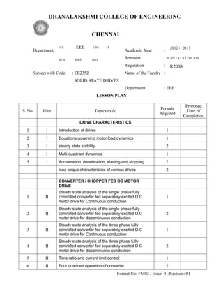
- 1. DHANALAKSHMI COLLEGE OF ENGINEERING CHENNAI ECE EEE CSE IT 2012 - 2013 Department: Academic Year : MCA MBA H&S Semester : III / IV / V / VI / VII /VIII Regulation : R2008 Subject with Code : EE2352 Name of the Faculty : SOLID STATE DRIVES Department : EEE LESSON PLAN Proposed Periods S. No. Unit Topics to do Date of Required Completion DRIVE CHARACTERISTICS 1 I Introduction of drives 1 2 I Equations governing motor load dynamics 1 3 I steady state stability 2 4 I Multi quadrant dynamics 1 5 I Acceleration, deceleration, starting and stopping 2 load torque characteristics of various drives 2 CONVERTER / CHOPPER FED DC MOTOR DRIVE Steady state analysis of the single phase fully 1 II controlled converter fed separately excited D.C 1 motor drive for Continuous conduction Steady state analysis of the single phase fully 2 II controlled converter fed separately excited D.C 2 motor drive for discontinuous conduction Steady state analysis of the three phase fully 3 II controlled converter fed separately excited D.C 1 motor drive for Continuous conduction Steady state analysis of the three phase fully 4 II controlled converter fed separately excited D.C 2 motor drive for discontinuous conduction 5 II Time ratio and current limit control 1 6 II Four quadrant operation of converter 2 Format No: FM02 / Issue: 01/Revison: 01
- 2. DESIGN OF CONTROLLERS FOR DRIVES 1 III Transfer function for DC motor, load and converter 1 2 III Closed loop control with current feedback 1 3 III Closed loop control with speed feedback 1 Armature voltage control and field weakening mode 4 III 2 control 5 III Design of controllers: Current controller 1 6 III Design of controllers: speed controller 1 7 III Converter selection and characteristics 1 8 III Use of simulation software package 1 INDUCTION MOTOR DRIVES 1 IV Stator voltage control 1 2 IV Energy efficient drive 1 3 IV v/f control, constant air-gap flux 2 4 IV Field weakening mode 1 5 IV voltage/current fed inverters 1 6 IV Block diagram of vector control 2 7 IV closed loop control 1 SYNCHRONOUS MOTOR DRIVES 1 V V/f control of synchronous motor 1 2 V Self-control of synchronous motor 2 3 V Marginal angle control 2 4 V Power factor control 1 5 V Permanent magnet synchronous motor 2 6 V Black diagram of closed loop control 1 Signature of Class HOD Signature of Faculty Signature of Faculty HOD Format No: FM02 / Issue: 01/Revison: 01
- 3. DESIGN OF CONTROLLERS FOR DRIVES 1 III Transfer function for DC motor, load and converter 1 2 III Closed loop control with current feedback 1 3 III Closed loop control with speed feedback 1 Armature voltage control and field weakening mode 4 III 2 control 5 III Design of controllers: Current controller 1 6 III Design of controllers: speed controller 1 7 III Converter selection and characteristics 1 8 III Use of simulation software package 1 INDUCTION MOTOR DRIVES 1 IV Stator voltage control 1 2 IV Energy efficient drive 1 3 IV v/f control, constant air-gap flux 2 4 IV Field weakening mode 1 5 IV voltage/current fed inverters 1 6 IV Block diagram of vector control 2 7 IV closed loop control 1 SYNCHRONOUS MOTOR DRIVES 1 V V/f control of synchronous motor 1 2 V Self-control of synchronous motor 2 3 V Marginal angle control 2 4 V Power factor control 1 5 V Permanent magnet synchronous motor 2 6 V Black diagram of closed loop control 1 Signature of Class HOD Signature of Faculty Signature of Faculty HOD Format No: FM02 / Issue: 01/Revison: 01
- 4. DESIGN OF CONTROLLERS FOR DRIVES 1 III Transfer function for DC motor, load and converter 1 2 III Closed loop control with current feedback 1 3 III Closed loop control with speed feedback 1 Armature voltage control and field weakening mode 4 III 2 control 5 III Design of controllers: Current controller 1 6 III Design of controllers: speed controller 1 7 III Converter selection and characteristics 1 8 III Use of simulation software package 1 INDUCTION MOTOR DRIVES 1 IV Stator voltage control 1 2 IV Energy efficient drive 1 3 IV v/f control, constant air-gap flux 2 4 IV Field weakening mode 1 5 IV voltage/current fed inverters 1 6 IV Block diagram of vector control 2 7 IV closed loop control 1 SYNCHRONOUS MOTOR DRIVES 1 V V/f control of synchronous motor 1 2 V Self-control of synchronous motor 2 3 V Marginal angle control 2 4 V Power factor control 1 5 V Permanent magnet synchronous motor 2 6 V Black diagram of closed loop control 1 Signature of Class HOD Signature of Faculty Signature of Faculty HOD Format No: FM02 / Issue: 01/Revison: 01
- 5. DESIGN OF CONTROLLERS FOR DRIVES 1 III Transfer function for DC motor, load and converter 1 2 III Closed loop control with current feedback 1 3 III Closed loop control with speed feedback 1 Armature voltage control and field weakening mode 4 III 2 control 5 III Design of controllers: Current controller 1 6 III Design of controllers: speed controller 1 7 III Converter selection and characteristics 1 8 III Use of simulation software package 1 INDUCTION MOTOR DRIVES 1 IV Stator voltage control 1 2 IV Energy efficient drive 1 3 IV v/f control, constant air-gap flux 2 4 IV Field weakening mode 1 5 IV voltage/current fed inverters 1 6 IV Block diagram of vector control 2 7 IV closed loop control 1 SYNCHRONOUS MOTOR DRIVES 1 V V/f control of synchronous motor 1 2 V Self-control of synchronous motor 2 3 V Marginal angle control 2 4 V Power factor control 1 5 V Permanent magnet synchronous motor 2 6 V Black diagram of closed loop control 1 Signature of Class HOD Signature of Faculty Signature of Faculty HOD Format No: FM02 / Issue: 01/Revison: 01