2. Imprint:
Responsibility for the contents
ZF Getriebe GmbH, Department MKTD,
Saarbrücken, Germany
Printed by HAGER PAPPRINT GmbH, Kirkel
Printed in Germany
Reproduction, printing or translation either
wholly or in part isprohibited.
Published by ZF Getriebe GmbH,
Saarbrücken, Department MKTD
Printed in Germany by
HAGER PAPPRINT GmbH, Kirkel.
Item No. 1060 754 002
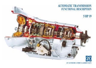
3. Introduction / Note Function description 5 HP 19
Contents Page
Introduction / note 1
Contents 2
This brief technical description is intended to provide information on
the component parts, design and function of the automatic transmission. Sectional view of the 5 HP 19 automatic transmission 3
Key 5
Status of information: March 1998
General description of the transmission (brief description) 6
Alterations and additions to the technical data are contained in the rele-
vant current “Technical Service” information. – Planetary gear (Ravigneaux), planetary gear (rear-mounted) 9
Description of individual components 10
– Converter 11
– Oil pump 14
– Volume control valve 15
– Control elements: clutch, freewheel 16
– Overlap circuit 20
– Selector lever positions: P, R, N, D + one-touch gate 21
– Position switch 26
– Parking lock 27
– Descriptions of individual gears 28
– Solenoid valve and clutch logic 34
– Power flow / closed control elements 35
– Hydraulic selector unit 36
– Hydraulic control diagram (DIN) 46
– Electronic Transmission Control (EGS) 47
– Pin assignment (EGS modular 134-pole connector), block diagram 48
– Automatic transmission oil filling 51
– Technical data 52
– Notes 53/54
Function description 5 HP 19 March 1998 Function description 5 HP 19 March 1998
ZFS, Department MKTD 1 ZFS, Department MKTD 2
5. Key
1 Turbine )
2 Converter lock-up clutch piston )
3 Stator ) Torque converter
4 Converter cover )
5 Pump )
6 Transmission housing
7 Multi-disc brake C
8 Multi-plate clutch B
9 Multi-plate clutch E
10 Multi-disc brake A
11 Ravigneaux planetary gear set
12 Multi-disc brake D
13 Freewheel, 1st gear
14 Multi-disc brake G
15 Multi-plate clutch F
16 Single rear-mounted planetary gear set
17 Parking lock gear
18 Gearbox extension complete with preset bearing
19 Output flange
20 ATF pump - crescent-type
21 Flow control valve
22 ATF drain screw
23 Magnet
24 Oil pan
25 Oil filter
26 Speed sensor, gearbox rotating speed/turbine (Hall-effect generator)
27 EDS-1 pressure control valve for modulation/system pressure
28 Hydraulic control unit
29 Solenoid valves 1, 2 and 3 and pressure control valves EDS 2, 3 and 4
30 Speed sensor, gearbox output speed (inductive sensor)
31 ATF filler cap (at side of transmission housing)
Key to picture on page 6:
1 Hydrodynamic torque converter 5 Oil filler
2 Heat exchanger connections 6 Breather
2a) Intercooler input 7 Selector lever connection
2b) Intercooler output 8 Plug connection for electronic con-
3 Output flange trol unit
4 Oil drain 9 Plug connection for electronic posi-
tion switch
Function description 5 HP 19 March 1998
ZFS, Department MKTD 5
6. Brief general description
The ZF 5 HP 19 automatic transmission was developed for cars with a power output of
110 kW to 150 kW.
It is positioned longitudinally in relation to the vehicle’s forward travel direction, to match the engine’s
installed position . The mechanical elements use the planetary gear principle, with an electronic-
hydraulic control unit; the hydraulic control unit is attached to the transmission, the electronic control
unit (German abbreviation: EGS) to the vehicle.
Rear-wheel drive
Function description 5 HP 19 March 1998
ZFS, Department MKTD 6
7. Power is supplied to the transmission through a hydrodynamic torque converter with an integrated
converter lock-up clutch.
The transmission’s capacity ratings are:
– max. power input: 150 kW (204 bhp)
– max. torque: 300 Nm
The 5 forward gears and 1 reverse gear are obtained by means of a Ravigneaux double planetary gear
set and a rear-mounted single planetary gear set with one spider.
Ravigneaux planetary gear set
This consists of: 2 sun wheels of different sizes
3 matching planetary gears,
1 planetary spider
1 annulus
Function description 5 HP 19 March 1998
ZFS, Department MKTD 7
8. Rear-mounted planetary gear set
This consists of: 1 sun wheel
4 matching planetary gears
1 planetary spider
1 annulus
The individual gear ratios are obtained by introducing torque at certain elements of the planetary gear
train, while other elements are braked.
Power is always transmitted to the output shaft via the annulus or ring gear (see power flow descripti-
on).
The mechanical ratios are as follows:
Gear: 1st 2nd 3rd 4th 5th Rev.
Ratio: 3.67 2.0 1.41 1.0 0.74 4.10
Function description 5 HP 19 March 1998
ZFS, Department MKTD 8
9. Action of shift elements
Planetary gears (Ravigneaux) Planetary gear (rear-mounted)
ZFS, Department MKTD
3 4 5 6 7
Function description 5 HP 19
2
1
9
1 Multi-plate clutch E 3 Multi-plate clutch B + brake C 5 Multi-plate clutch F
March 1998
2 Multi-plate clutch A 4 Multi-disc brake D + 1st-gear freewheel 6 Multi-disc brake G 7 Output shaft
10. Description of individual components
The hydrodynamic torque converter
1. Converter operating principle
The converter consists of the impeller, the turbine wheel, the reaction member (stator) and the oil
(Automatic Transmission fluid or ATF) necessary for transmitting the torque.
The impeller, which is driven by the engine, causes the oil in the converter to flow in a circular
pattern. This oil flow strikes the turbine wheel, where its direction of flow is deflected.
In the hub area, the oil leaves the turbine and enters the reaction member (stator), where it is again
deflected before reaching the impeller with the correct input flow direction.
The reversal effect generates a torque at the stator, the reaction to which is used to amplify the
turbine torque.
The relation between turbine torque and pump torque is referred to as torque multiplication.
The greater the difference in speed between the pump and the turbine, the greater the torque mul-
tiplication; it is at its highest when the turbine is at a standstill. The higher the speed of the turbi-
ne, the lower the torque multiplication.
When turbine speed reaches about 85 % of pump speed, torque multiplication = 1, that is to say
turbine torque is equivalent to pump torque.
The stator, which bears against the housing via the freewheel, then rotates freely in the oil flow
and the freewheel is overrun. From this point onwards, the converter acts as a straightforward
fluid coupling. The stator is at a standstill during the conversion process, conversion, and bears
against the housing via the freewheel.
(See diagram)
Impeller Turbine wheel
From
engine
To transmission
Condition at
moment of driving nT = 0
off (stationary Stator Vehicle at a
stator) standstill
Intermediate con- nT < nP
dition (stationary
stator) nT < nP
Status in so-called Turbine wheel turns
coupling range slightly slower than
(stator rotating) impeller
Function description 5 HP 19 March 1998
ZFS, Department MKTD 10
11. 5 HP 19 torque converter
4
5
3
6
7
8
9
2
1
Upper half: W 254 2 GWK
Lower half: W 254 1 GWK
1 Converter cover 6 Freewheel
2 Lock-up clutch piston 7 Stator shaft
3 Engine connection 8 Turbine shaft (input shaft)
4 Turbine 9 Stator
5 Pump
Function description 5 HP 19 March 1998
ZFS, Department MKTD 11
12. 2. Torque converter lock-up clutch
The torque converter lock-up clutch is a device which eliminates converter slip and thus helps to
improve fuel consumption.
The previous control principle for converter lock-up clutch operation has been replaced on the 5
HP 19by a controlled-slip function . The converter lock-up clutch is engaged and released in a
regulated manner. During the controlled-slip phase, a slight speed difference between the impeller
and turbine is permitted. This ensures that torsional vibration from the engine is not passed on to
the transmission, thus enhancing shift quality and acoustic performance.
Lock-up clutch piston pressure is controlled by an electronic pressure control valve (EDS4) (see
oil flow diagram).
2 3 4 5
n/engine
6
7
1
1 Space behind lock-up clutch
piston 5 Turbine
2 Clutch plate lining 6 Pump
3 Lock-up clutch piston 7 Stator
4 Converter cover
Function description 5 HP 19 March 1998
ZFS, Department MKTD 12
13. 3. Hydraulic and mechanical power flow in
the converter:
When open (in the torque conversion
range), the oil pressures behind the conver-
ter lock-up clutch piston and in the turbine
zone are equal. The direction of flow is
through the turbine shaft and the space
behind the piston, to the turbine chamber.
Lock-up clutch/open
n/engine > n/turbine
To engage the lock-up clutch, the direction
of flow is modified (reversed) by means of
a valve in the hydraulic selector unit. At the
same time, the space behind the lock-up
clutch piston is vented. Oil pressure passes
from the turbine chamber to the lock-up
clutch piston and presses it against the con-
verter cover (outer shell). The turbine is
then locked by the lined plate between the
piston and cover, and permits rigid through-
drive to the planetary gear train with no
slip (or reduced slip if regulated).
Lock-up clutch/engaged
n/engine = n/turbine
Function description 5 HP 19 March 1998
ZFS, Department MKTD 13
14. Oil pump
The oil pump is a crescent-type pump with a delivery rate of about 24 cm3 per revolution; it is located
between the torque converter and the transmission housing.
The converter is located in the pump by a plain bearing. The pump is driven directly from the engine
via the converter shell, and supplies the transmission and selector unit with oil.
The pump draws in oil through a filter and pumps pressurized oil through the flow regulating valve,
which at higher operating speeds returns any excess pressurized oil directly to the pump’s intake side.
The pressurized oil is pumped from the flow regulating valve through the main pressure valve in the
hydraulic selector unit, where the oil pressure is modified and the surplus oil returned to the sump.
1
8 5
2 6
3 7
4
8
1 Sealing ring 5 Pump housing
2 Disc 6 Pump ring gear
3 Shaft sealing ring 7 Impeller
4 Bearing bush 8 Centering sleeve
Function description 5 HP 19 March 1998
ZFS, Department MKTD 14
15. Flow regulating valve diagram (MRV)
Intermediate plate
PUMP
Flow regulating valve
POSITION SWITCH
5 HP 19 pump charging
Transmission delivery rate (l/min)
Engine speed (l/min)
Function description 5 HP 19 March 1998
ZFS, Department MKTD 15
16. Shift elements
In addition to the converter lock-up clutch, the shift elements include a sprag-type freewheel:
– freewheel for 1st gear, for shifting from 1 to 2 and 2 to 1, beneath brake D
– four rotating multi-plate clutches A, B, E and F
– three fixed multi-disc brakes C, D and G
Shifting from 1 to 2 and 2 to 1 is supported by the sprag-type freewheel, so that there is no overlap-
ping of the two clutches or brakes.
Overlap occurs when shifting from 2-3, 3-4, 4-5 and 5-4, 4-3, 3-2. In other words, during the shift one
clutch must remain capable of transmitting the drive at a reduced main pressure until the correspon-
ding clutch can accept the incoming torque.
The shift elements, clutches or brakes are engaged hydraulically. The pressurized oil reaches the space
between the cylinder and piston, as a result of which the plates are compressed. When the oil pressure
drops, the diaphragm spring acting on the piston presses the piston back to its initial position.
The shift elements are designed to permit gearshifts under load without interrupting the tractive force.
Muli-plate clutches A, B, E and F supply engine power to the planetary gear train, with multi-disc bra-
kes C, D and G reacting to the torque at the housing.
Function description 5 HP 19 March 1998
ZFS, Department MKTD 16
17. 1 2 3 4
ZFS, Department MKTD
Function description 5 HP 19
5
17
6
1 Vent
2 Cylinder for brake G
3 Brake G
4 Transmission housing 7
5 Cylinder for clutch F
6 Clutch F
7 Cylinder for brake G (external plate carrier)
March 1998
locked to the transmission housing (with screws)
18. Example of a multi-plate clutch (clutch E)
The dynamic pressure at clutch E is equal i.e. the clutch piston is pressurized with oil from both sides
in order to prevent speed-dependent pressure build-up in the clutch. This equalizing effect is achieved
via tha baffle plate (7) and the pressureless oil supply via the lubrication channel (1), which fills the
space between the piston and baffle plate with oil.
The advantages of this dynamic pressure equalization are:
– reliable opening and engaging of the clutch in all speed ranges
– smoother shifts
2 3 4 5 6
7
1 8 9
10 11 12
1 Lubrication channel 7 Baffle plate
2 Input (input shaft), 8 Diaphragm spring
cylinder E 9 Output (interior plate carrier)
3 Main pressure, clutch E 10 Space between piston and cylinder
4 Piston E 11 Space for dynamic pressure
5 Cylinder E (external plate carrier) equalization
6 Clutch assembly 12 Bearing
Function description 5 HP 19 March 1998
ZFS, Department MKTD 18
19. Example of a freewheel
Sprag-type freewheel
Purpose and operating principle of the freewheel:
The freewheel transfers torque in one direction only, and rotates freely in the other. Its purpose is to
simplify the shift operation in technical terms without interrupting the flow of the tractive force, and
to achieve consistent shift quality.
Direction of rotation:
The sprag blocks are located in the space bet-
ween the inner and outer ring in such a way
that these can turn in relation to one another.
Locking direction:
The sprag blocks between the inner and outer
rings are asymmetrically shaped, and are rai-
sed upright when the rings turn in opposite
directions. They consequently become lodged
between the inner and outer rings, preventing
any relative movement of these two compo-
nents. The sprag blocks are located in a speci-
al cage.
Function description 5 HP 19 March 1998
ZFS, Department MKTD 19
20. Overlap control
In the case of the overlap shift procedures 2-3, 3-4, 4-5 and 5-4, 4-3, 3-2, the place of the freewheel is
taken by suitable control of the clutches. The appropriate clutches are energized by electronic-hydrau-
lic means. This saves both space and weight.
The electronic-hydraulic circuit is formed by various valves within the hydraulic selector unit, which
are energized by means of pressure regulators.
These elements cause the appropriate clutches or brakes to cut in or out at the right moment.
The electronic control unit is located away from the transmission, at a separate point
(see electronic control unit).
Diagrams of overlap control (upshift)
Speed Engine speed
Speed
characteristic
Time
Pressure
Pressure, cut-in clutch Pressure
variation
Pressure, cut-out clutch
Time
Torque
Output
Torque
characteristic
Pressure Pressure
cut-in clutch cut-out clutch
Control phase Load transfer Time
Function description 5 HP 19 March 1998
ZFS, Department MKTD 20
21. Selector lever positions
1. General information
Gears are obtained by moving the selector lever, which is connected to the hydraulic
selector unit.
The transmission positions
(P, R, N, D)
are simultaneously supplied to the electronic control unit in encoded form by a switch (position
switch) mounted on the transmission selector shaft.
Automatic transmission Mechanical positions
P
+ R
N
One-touch gear shift D
Position switch –
Selector unit
Module connector
Function description 5 HP 19 March 1998
ZFS, Department MKTD 21
22. 2. Selector lever positions
The following positions can be obtained manually
with the selector lever. P
+ R
N
D
–
Position / function
P = Park, must only be engaged if the vehicle is at a standstill. Procedure: first apply handbrake,
then engage position P.
R = Reverse, must only be engaged if the vehicle is at a standstill and the engine idling.
N = Neutral, when the vehicle is at a standstill, apply the handbrake first to prevent the vehicle
from rolling away. When the vehicle is moving, only select “Neutral” in order to counteract
skidding.
D = Drive, automatic-shift position for normal driving. Automatic gearshifts from 1st to 5th and
5th to 1st and all intermediate gears.
The 5th, 4th, 3rd, 2nd and 1st gears are shifted up by moving the lever in the direction of the
plus (+) symbol or down by moving the lever in the direction of the minus (-) symbol in the
manual program (one-touch mode). The currently selected gear is retained (see M program).
4th gear: Select this position if the transmission tends to hunt between 5th-4th/4th-5th in
certain driving conditions (only possible in Steptronic mode).
3rd gear: Select this position if the transmission tends to hunt between 3rd and 5th in cer-
tain driving conditions. Also recommended for lengthy descents (only available in
Steptronic mode).
2nd gear: Select this position when driving over mountain passes with lengthy ascents and
descents (only available in Steptronic mode).
Advantages: - more effective use of engine’s power
- engine braking utilized
- unnecessary up- and down-shifts avoided.
1. Gang: Selecting 1st gear always has a braking effect
(only in the M mode).
Function description 5 HP 19 March 1998
ZFS, Department MKTD 22
23. 5 HP 19 BMW - program selection
M-program
- manual P
up-shifts + R
- manual
N
down-shifts
D
XE-program
S-program
–
The individual programs are no longer selected by the program button, but by moving the selector
lever to the appropriate gate.
There are three programs available.
Shifting to blue (D) = XE - program
Adaptive Transmission Control (AGS)
Shifting to red (S) = S - program
without touching Adaptive Transmission Control (AGS)
+ or -
Shifting from red to = M - program (one-touch mode)
+ or -
Function description 5 HP 19 March 1998
ZFS, Department MKTD 23
24. XE-program (AGS)
Standard drive program in position D.
P
The adaptive transmission control (AGS) has
variousdrive programs, e.g.:
+ R
- Trailer towing
- Mountain driving N
- Highway/motorway driving D
(constant speed)
- Cornering
The programs are selected by the electronic con-
trol unit, which automatically modifies the trans-
–
mission’s shift characteristics according to rolling
resistance, load, accelerator pedal movement and
the road situation.
BMW 5 HP 19 AGS program architecture
Drive-off Kick-Fast Driving Braking
operation
evaluation evaluation evaluation evaluation
Uphill dri- Evaluation of the
S/D gate ving reco- type of driver
gnition
Shift program selection
Downhill Fast-Off Corner
driving recognition Selector lever
recognition recognition
Gear selection
Function description 5 HP 19 March 1998
ZFS, Department MKTD 24
25. S-program 5 HP 19 BMW
S-program
The S program is a performance-oriented pro-
gram with the transmission’s shift characteristics P
moved up to higher engine speeds. To select the
program the selector lever is moved across into + R
the left gate, but without moving farther to + or -.
N
Gears 1-4 and 4-1 are selected automatically. D
5th gear is locked out of action.
–
M-program 5 HP 19 BMW
M-program (one-touch mode)
The M program is a manual shift program which is
activated by pushing the lever to + or - in the left P
gate.
+ R
It is possible to drive off in gears 1 or 2; 1st gear is
intended principally to provide an engine braking N
effect. D
3rd gear can be selected manually above a speed of
about 10 km/h, 4th gear from approx. 35 km/h and
5th gear from around 45 km/h.
–
Every time the lever is moved to + a sequential up-
shift takes place.
Every time the lever is moved to - a sequential
down-shift takes place.
Function description 5 HP 19 March 1998
ZFS, Department MKTD 25
26. The position selector
The position selector is situated on the transmission’s selector shaft and is designed to carry out two
tasks:
1. To inform the EGS by means of an electronic signal of the transmission’s mechanical selector lever
position (P, R, N, D, 4, 3, 2). Positions 4, 3 and 2 are selected in one-touch mode.
2. To prevent the engine from starting in the drive positions R, D, 4, 3 or 2), but to enable it to start
when the vehicle is stationary (in P or N).
Coding table
P Z1 R Z2 N Z2 D Z3 4 3 2
L1 1 1 1 1 1 1 0 0 0 0 1
L2 1 0 0 0 1 0 0 0 0 0 0
L3 0 0 0 1 1 1 1 0 0 1 1
L4 1 1 0 0 0 0 0 0 1 1 1
Function description 5 HP 19 March 1998
ZFS, Department MKTD 26
27. Parking lock (5 HP 19 rear-wheel drive)
The parking lock is a device for preventing the car from rolling away.
It is engaged (purely mechanically) at the selector lever with the vehicle at a standstill and prevents
the output shaft from turning by means of a pawl which engages in the teeth on the parking lock gear.
The rear-axle differential is then locked by way of the propeller shaft.
4
3
2 1
1 Pawl
2 Connecting rod
3 Output shaft
4 Parking lock gear
Function description 5 HP 19 March 1998
ZFS, Department MKTD 27
28. Description of individual gears
Power flow in 1st gear
In 1st gear, the power is introduced from the torque converter purely hydraulically to the front plane-
tary gear train . The connection between the converter turbine and the sunwheel (2) in the planetary
gear set is established by a rotating multi-plate clutch, clutch A. The freewheel beneath the multi-disc
brake D locks the planetary gear set’s spider when rotating to the left. Sunwheel 2 drives the planetary
gears that are meshed with planetary gears I. These in turn drive the ring gear which is connected to
the ring gear support and the ring gear (interior disc support brake G) of the in-series planetary gear
set by a spider shaft.
The multi-disc brake G blocks the sunwheel of the rear-mounted planetary gear set via the cylinder of
the multi-plate clutch F. This causes the spider to be driven.
The spider is connected with the output shaft.
Spider speed = output speed
In 1st gear, with braking effect when coasting, the multi-disc brake D is also engaged, i.e. the spider
of the front planetary gear set is blocked.
Ring gear
Short planetary gear
Long planetary gear
Sunwheel 1
Planet carrier
Sunwheel 2
Function description 5 HP 19 March 1998
ZFS, Department MKTD 28
29. Power flow in 2nd gear
In the same way as for the 1st gear, the sunwheel 2 of the front planetary gear set is driven via the tur-
bine shaft and clutch A.
The sunwheel 1 is locked by the multi-disc brake C.
Planetary gears 2 drive planetary gears 1, which roll around the stationary sunwheel 1.
Output is as for 1st gear via the ring gear of the front and the in-series planetary gear set, the spider
and simultaneously the output shaft.
Ring gear
Short planetary gear
Long planetary gear
Sunwheel 1
Planet carrier
Sunwheel 2
Function description 5 HP 19 March 1998
ZFS, Department MKTD 29
30. Power flow in 3rd gear
The sunwheel 2 is once again, as for gears 1 and 2, driven via the converter turbine shaft and clutch
A. Multi-disc brake C blocks the sunwheel 1. The planet carriers 2 drive the planetary gears 1 which
roll around the stationary sunwheel 1. Output is then accomplished, as in gears 1 and 2, via the ring
gear of the front and the in-series planetary gear set. The planetary gears are driven via the ring gear
through the engaged multi-plate clutch F. Unlike in 1st and 2nd gears, through-drive in the rear-moun-
ted planetary gear set is thus achieved.
Ring gear
Short planetary gear
Long planetary gear
Sunwheel 1
Planet carrier
Sunwheel 2
Function description 5 HP 19 March 1998
ZFS, Department MKTD 30
31. Power flow in 4th gear
Power is transmitted via the turbine shaft with the multi-plate clutches A and E engaged.
Multi-plate clutch A drives the sunwheel 2 and multi-plate clutch E the spider of the front planetary
gear set at engine speed.
The ring gear is driven to the right (in the direction of engine rotation) as a result of the inertial thrust
of the vehicle mass thrust, thereby locking the planetary gears (through-drive at the front planetary
gear set). Consequently, the ring gear of the rear-mounted planetary gear set is driven at engine speed.
The planetary gear of the rear-mounted planetary gear set is driven by the engaged multi-plate clutch
F via the ring gear and the sun wheel. In this way, through-drive is achieved in the rear planetary gear
set as well.
Ring gear
Short planetary gear
Long planetary gear
Sunwheel 1
Planet carrier
Sunwheel 2
Function description 5 HP 19 March 1998
ZFS, Department MKTD 31
32. Power flow in 5th gear
Power transmission is via the converter’s turbine shaft and the engaged multi-plate clutch E. The inner
plate carrier of the clutch E meshes with the planetary spider.
The sun wheel 1 is locked via the body of multi-disc brake C.
The planetary gears 1 then roll around the sunwheel 1 and thereby drive the ring gear of the rear-
mounted planetary gear set which is in the through-drive setting as in 3rd and 4th gear.
Ring gear
Short planetary gear
Long planetary gear
Sunwheel 1
Planet carrier
Sunwheel 2
Function description 5 HP 19 March 1998
ZFS, Department MKTD 32
33. Power flow in reverse gear
Power transmission is via the turbine shaft and cylinder A (which is also the inner plate carrier of
clutch B) to the engaged multi-plate clutch B.
The engaged multi-plate clutch B transmits the power to the sunwheel 1 via the body.
Multi-plate clutch D is engaged and locks the planetary spider.
The planetary gears 1 thus cause the sunwheel 1 and the ring gear, which is connected via the spider
shaft to the ring gear carrier and the ring gear of the in-series planetary gear set (inner disc carrier,
brake G) , to reverse direction.
Ring gear
Short planetary gear
Long planetary gear
Sunwheel 1
Planet carrier
Sunwheel 2
Function description 5 HP 19 March 1998
ZFS, Department MKTD 33
35. Power flow – 5 HP 19
Power flow, 5 HP 19 version
Closed control elements
Gear Clutch Brake Free- Ratio Ratio
wheel steps
i
PHI
Total
depending on operating condition
Function description 5 HP 19 March 1998
ZFS, Department MKTD 35
36. Hydraulic selector unit
The hydraulic selector unit is located in the automatic transmission oil pan.
It contains electrical actuators and sensors, plus a number of hydraulic valves which are responsible,
together with the electronic control unit, for engaging the gears in the automatic transmission.
The electrical components:
Solenoid valves 1, 2 and 3 (MV)
Pressure regulators 1, 2, 3 and 4 (EDS) electronic pressure control
Speed sensor Turbine (turbine speed, transmission)
Speed sensor Output (output speed, transmission)
are arranged in such a way that they are accessible when the transmission is installed on the vehicle
(see drawing).
The temperature sensor is integrated into the wiring harness on the control-unit side.
Turbine Solenoid valves
speed System pressure Hydraulic and shift pressure Output speed
Oil filter sensor control selector unit controls sensor
Function description 5 HP 19 March 1998
ZFS, Department MKTD 36
37. The valves are located in the following valve housings:
Valve housing I
Clutch valve for clutch C (KV-C)
Clutch valve for clutch G (KV-G)
Clutch valve for clutch A (KV-A)
Clutch valve for clutch E (KV-E)
Traction valve for shifting 5 -> 4 (ZV5-4)
Main pressure valve (system pressure) (HD-V)
Retaining valve for clutch C (HV-C)
Retaining valve for clutch G (HV-G)
Selector gate for positions P, R, N, D, 4, 3, 2 (WS)
Function description 5 HP 19 March 1998
ZFS, Department MKTD 37
38. Brief description of valves
Clutch valves (KV-A, KV-C, KV-E, KV-G)
The clutch valves are variable pressure-reducing valves. They are controlled via the corresponding
pressure control valve (EDS) and determine clutch pressure during shifting.
Traction valve (shifting from 5 -> 4 / ZV 5 - 4)
Traction valve 5 -> 4 works as a clutch valve and fills clutch A initially when shifting from
5 -> 4.
Main pressure valve (system pressure / HD-V)
The main pressure valve is a variable pressure-limiting valve which controls the oil pressure generated
by the pump. Surplus oil flows back into the oil pan.
Retaining valve (for clutches C, G / HV-C, HV-G)
The retaining valves actuate the clutch valves, i.e.: the regulating function (regulating phase) of the
clutch valve during the gearshift is terminated by the main valve at the appropriate moment, as a
result of which clutch pressure rises to the same value as system pressure. Both valves (clutch and
retaining valves) are controlled by the corresponding pressure regulator (EDS).
Selector valve
The driver of the vehicle selects the direction of travel (forward or reverse), the park position and the
neutral position via the selector valve.
Function description 5 HP 19 March 1998
ZFS, Department MKTD 38
39. Valve housing II
Solenoid valve 1 (MV1)
Solenoid valve 2 (MV2)
Solenoid valve 3 (MV3)
Electronic pressure control valve 2 (EDS 2)
Electronic pressure control valve 3 (EDS 3)
Electronic pressure control valve 4 (EDS 4)
Traction/coasting valve (ZS-V)
Control valve for converter pressure (SV-WD)
Shift valve 1 (SV-1)
Shift valve 2 (SV-2)
Shift valve 3 (SV-3)
Reverse-gear valve (RG-V)
Pressure reduction valve 1 (DRV-1)
Function description 5 HP 19 March 1998
ZFS, Department MKTD 39
40. Brief description of valves
Solenoid valves 1, 2, 3 (MV 1, 2, 3)
There are three 3/2 solenoid valves in the hydraulic selector unit, i.e. 3 connections and 2 shift positi-
ons. The solenoid valves are energized by the electronic transmission control unit and have two positi-
ons (open or closed). Their purpose is to switch over the valves.
3/2 – Solenoid valve (MV)
Type: Plate-armature valve
Pressure range: 0 to 5 bar
Rated voltage: 12 V
Nom. diameter: 1.6 mm
Starting current: 166 mA
Pressure regulator (EDS 1, 2, 3, 4)
The electronic pressure regulating valves convert an electrical current into a proportional hydraulic
pressure. They are energized by the electronic transmission control unit and actuate the valves asso-
ciated with the shift components. The characteristic shown only applies to EDS 1; EDS 2, 3 and 4
have a rising characteristic.
Electrical pressure regulating valve (EDS)
Tolerance range
Control pressure (bar)
for falling pressure
characteristic
Adjusting point
Hysteresis
for rising pres-
sure characteristic
Control current (A)
Function description 5 HP 19 March 1998
ZFS, Department MKTD 40
41. Output speed sensor
(Inductive sensor)
Dimension “A”
Gap: < 0.25 mm (dimension A)
Interior resistance: 260 Ω ± 10 %
Function description 5 HP 19 March 1998
ZFS, Department MKTD 41
42. Turbine speed sensor
(Hall-effect sensor)
Hall-effect sensor Plug
V+
V-
Hall I. C. Electronic circuit
- Bipolar mono-cell
- ± 75 G
Function description 5 HP 19 March 1998
ZFS, Department MKTD 42
43. Traction/coasting valve (ZS-V)
The traction/coasting valve is supplied with oil from the pressure reduction valve and switches off the
regulating function of the traction valve 5 -> 4 if required.
Control valve for converter pressure (SV-WD)
The regulating function of the converter pressure valve is switched off by the control valve and the
space behind the converter clutch is therefore vented.
Shift valves 1, 2, 3 (SV 1, 2, 3)
The shift valves are actuated by the solenoid valves and direct the system pressure to the corres-
ponding clutch regulating circuits.
Reverse-gear valve (RG-V)
The reverse-gear valve has two functions:
1. Shift valve for reverse gear, and
2. Safety valve for the forward gears, to prevent inadvertent selection of
reverse.
It is actuated by the pressure at clutch A.
Pressure-reducing valve (DRV-1)
Pressure-reducing valve 1 lowers the system pressure at which the rear-mounted solenoid valves are
energized to approx. 5 bar. The solenoid valves require a constant input pressure in order to function.
Function description 5 HP 19 March 1998
ZFS, Department MKTD 43
44. Converter lock-up clutch housing (WK)
Valve for lubricating pressure (Schm.-V)
Converter lock-up clutch valve (WK-V)
Converter pressure valve (WD-V)
Valve for traction shifting 4 -> 5 (ZV 4-> 5)
Modulation pressure housing
Modulation pressure valve (Mod-V)
Pressure-reducing valve II (DRV II)
Electronic pressure control valve EDS 1 (DR-P)
Function description 5 HP 19 March 1998
ZFS, Department MKTD 44
45. Brief description of valves
Valve for lubricating pressure (Schm-V)
The lubricating valve reduces the system pressure and guarantees the necessary lubrication pressure.
Maximum pressure is also limited.
Converter clutch valve (WK-V)
The converter clutch valve is controlled by the electronic pressure control (EDS4) together with the
converter control valve (SV-W). In this function, thedirection of oil flow is reversed. The space in
front of the converter lock-up clutch is pressurized at system pressure and the control valve vents the
piston space behind the converter lock-up clutch.
Converter pressure control valve (WD-V)
The converter pressure valve reduces the system pressure and simultaneously maintains the required
pressure for the converter. Maximum converter pressure is limited to prevent the converter from being
distorted by excess pressure. When SV-WD is energized, the oil channel behind the lock-up clutch
piston is vented.
Valve for traction shifting 4 -> 5 (ZV 4-5)
The traction valve 4 -> 5 works as a clutch valve and serves to vent clutch C initially when a
4 -> 5 shift takes place.
Modulation pressure valve (Mod-V)
The modulation valve, which is energized by the electronic pressure control unit (EDS1), generates
the modulation pressure. The modulation pressure reaches the main pressure valve and thus has an
additional regulating effect on the main pressure. Modulation pressure is proportional to engine tor-
que.
Pressure-reducing valve II (DRV II)
Pressure-reducing valve II reduces system pressure to approx. 5 bar, which is applied to the downstre-
am pressure contrrol systems (EDS 1, 2, 3, 4) . Pressure control requires constant input pressure if it
is to function correctly.
Function description 5 HP 19 March 1998
ZFS, Department MKTD 45
47. Electronic Transmission Control (EGS)
Electronic Transmission Control (EGS) processes the following transmission, engine and vehicle sig-
nals (type of signal is shown in brackets):
From transmission
Turbine speed (frequency, inductive sensor)
Output speed (frequency, inductive sensor)
Transmission temp. (analog, resistor)
Version with CAN
From engine From vehicle
Engine speed (all engine Kick-down (digital)
Engine torque signals are P, R, N, D (4, 3, 2 -one-touch mode) (digital, encoded)
Throttle butterfly transmitted via Program (manual) (digital)
Engine temperature CAN bus) Brake light (digital)
Signals from other vehicle systems
These data include, for example:
– Shift characteristics for gears and the converter lock-up clutch
– Coordinating parameters for ressure calculation, engine manipulation and
time stages
– Regulator parameters for regulating gear shifts and converter lock-up
clutch
– Diagnosis parameters
The control program calculates the correct gear and lock-up clutch status, and also the optimum pres-
sure patterns for gear shifting and operation of the converter lock-up clutch, from the input signals
and the stored data.
EGS energizes the solenoid valves and pressure regulators via special output modules (output stages,
current regulating circuits) and thus influences the automatic transmission’s hydraulics.
The engine management system is also informed of the degree and duration of engine intervention via
the CAN bus.
On vehicles which are not equipped with CAN, the corresponding signals are transmitted via discrete
interfaces (BMWs are equipped with CAN in all cases).
Function description 5 HP 19 March 1998
ZFS, Department MKTD 47
48. Pin assignment – EGS 8.60 BMW (134 poles)
Connector specifications Module 3 (car body)
No. Assignment Note
A modular plug contact system with 5 chambers is used at the control unit end 3.01 Lifting magnet shift-lock
(BMW diagram x xxx xxx) as a pin contact system. The pin housing for the 3.02 Power supply lifting magnet shift-lock
transmission control is to be blue so it can be distinguished from other control 3.03 PIN signal ignition lock Bridge to pin 4.24
ZFS, Department MKTD
3.09 Program switch A program
units. The connectors are not encoded. The drawing numbers have yet to be
3.10 Program switch S program
Function description 5 HP 19
defined. 3.14 FGR controller only 5 HP 24
3.15 Brake light signal ... only 5 HP 24
The middle row of contacts in the power circuits have a leading function, in 3.16 Brake light signal ... only 5 HP 24
the signal circuits the upper and lower row of contacts have a leading function. 3.17 Kick-down signal
3.18 Steptronic: manual gate
3.19 Steptronic: tip-up
3.20 Steptronic: tip-down
Pin assignment Module 4 (transmission) (Assignment by control unit manufacturers)
No. Assignment Note
Modular plug inputs and outputs are divided according to functional groups. 4.02 Output speed ...
4.03 Output speed
Module 1: is fixed due to PS-10 compatibility and cannot be changed 4.04 Transmission switch ...
4.05 Input speed ...
48
Module 2: Chamber remains vacant (no contact pins in the plug)
4.06 Electronic ... EDS ... only 5 HP 24/3G
Module 3: half equipped, pin 27 ... 52 not pressed in, assignment 4.07 ... EDS ...
according to list 4.11 Power supply EDS 4
Module 4: fully equipped, assignment/layout according to project 4.12 Oil temperature sensor
Module 5: Chamber remains vacant (no contact pins in the plug). 4.13 Output speed ...
4.14 Transmission switch ...
4.16 Solenoid valve MV3
4.17 Electronic pressure ...
4.21 MV power supply
4.22 Oil temperature sensor
4.23 Input speed ...
4.24 Transmission switch line 2 Bridge to pin 3.03
4.26 Solenoid valve MV2
Module 1 (power supply) 4.27 Electr. pressure ...EDS ...
No. Assignment Note 4.28 Electr. pressure ... EDS
1.01 Ignition ... Bridge to pin 4.31 4.31 Transmission switch power supply Bridge to pin 1.01
1.02 4.32 Diagnosis ... Bridge to pin 1.03
1.03 Diagnosis ... 4.33 Input speed ...
1.04 Electronic mass Kl. 31E 4.34 Transmission switch ...
1.05 Power mass Kl. 31L 4.35 CAN bus ...
1.06 Power mass Kl. 31L 4.36 CAN bus high
1.07 Permanent positive supply 4.37 CAN bus low
1.08 DME relay Kl. 37 Bridge to pin 1.03 4.38 Solenoid valve MV1
4.40 Reversing light only ...
March 1998
1.09 DME relay Kl. 37 Bridge to pin 1.03
49. EGS plug module
ZFS, Department MKTD
Function description 5 HP 19
49
Transmission plug pin assignment – 5 HP 19 BMW
GE yellow 1 n / output (inductive sensor)
GR grey 2 EDS 1
OR orange 3 EDS 2
WS white 4 MV 3
BL blue 5 n / turbine + (Hall-effect sensor)
WE white 6 n / turbine - (Hall-effect sensor)
GE yellow 7 EDS 3
GR grey 8 MV 1
GN green 9 MV 2
GE yellow 10 n / output (inductive sensor)
RT red 11 EDS 4
VI violet 12 BN ( + )
OR orange 13 Temperature sensor +
WS white 14 Temperature sensor -
VI violet 15 Bn ( + )
March 1998
50. Pin assignment – 5 HP 19 BMW GS 8.60
Function description 5 HP 19 March 1998
ZFS, Department MKTD 50
51. Automatic transmission oil filling
(Overflow screw)
General requirements before checking or correcting the oil level:
– The vehicle has to be positioned horizontally on the hoist.
– The driven wheels or the transmission output have to be at a standstill for at least
two minutes before the oil level is checked.
– Selection lever in position P. Engage handbrake.
– The EGS must not be in the emergency program.
– Energy-consuming devices such as air conditioning must be turned off.
– When opening the ATF filling screw, the transmission sump temperature has to be
≤ 30° C.
– The transmission oil temperature check must be made with the correct testing
device.
Checking the oil level:
– Start the engine and select various gears. Engage R and D, shift up to the 3rd gear
step by step (gears remain engaged for 3 seconds each), engage position P.
– Idle speed 650–950 rpm (according to car manufacturer’s specification).
– Open the screw at the overflow hole.
– Add ATF at approx. ≤ 30° C until it overflows.
Transmission temperature increases during idle, oil expands and escapes.
– Close overflow hole when 40° C (+ 10° C) are reached.
Settling time between opening and closing the oil filling cap at least 60 seconds.
Starting temperature ≤ 30° C.
Important! – Oil level checking at regular operating temperature is not possible.
– Checking or adjustment of the oil level is only necessary after repair work on the
transmission, the cooling system or the pipes.
The transmissions are filled to the overflow point with lifetime oil (ESSO LT 71
141) at an oil temperature of 40° C before leaving the factory.
– If the filling screw is opened at operating temperature (80°), not enough oil will
remain in the transmission due to overflow and it will consequently fail.
– If the overflow hole is closed after adjustment at below 37° C, the transmission
will be too full.
– The temperature range (opening at 30° C, closing at 40° C) should be complied
with as closely as possible.
– Oil level adjustment in the emergency program is prohibited.
Function description 5 HP 19 March 1998
ZFS, Department MKTD 51
52. 5 HP 19 passenger car automatic transmission
Technical data
TRANSMISSION TYPE: Passenger car automatic transmission, 5-speed,
conventional driveline layout
TRANSMISSION POWER Tmax engine at 3,500 min-1 = 300 Nm
HANDLING CAPACITY: Pmax engine at 6,000 min-1 = 150 kW (204 bhp)
nmax in 1st to 4th gear = 6,540 min-1
nmax in 1st to 5th gear = 5,000 min-1
nmax Kick-down operation = 6,400 min-1
Tmax Turbine = 540 Nm
CONVERTER: W 254 S with GWK (lock-up clutch)
Tp = 90 - 230 Nm at np = 2,000 min-1
RATIOS: 1st gear 2nd gear 3rd gear 4th gear 5th gear Reverse
Gears: 3.67 2.0 1.41 1.0 0.74 4.10
POSITIONS: P, R, N, D (4, 3, 2)
CONTROL: Electro-hydraulic
Various shift programs available
WEIGHT WITH OIL: 77–79 kg depending on version
Engine application 5HP18 5HP19 Difference
M52B28 84.0kg 79.5kg 4.5kg
M52B25 84.0kg 78.9kg 5.1kg
M52B20 79.8kg 76.6kg 3.2kg
TRANSMISSION OIL: Lifetime oil filling
Function description 5 HP 19 March 1998
ZFS, Department MKTD 52