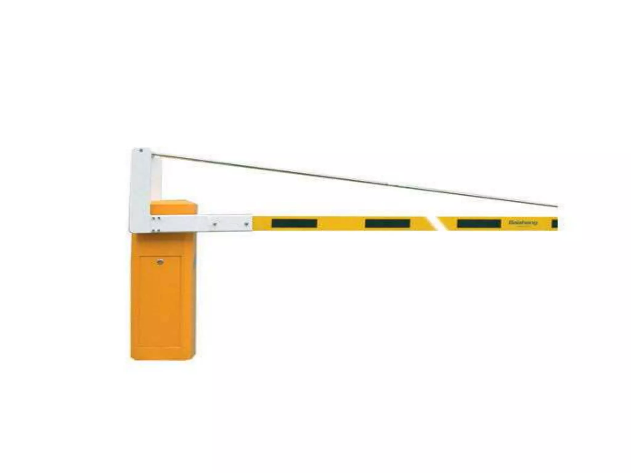
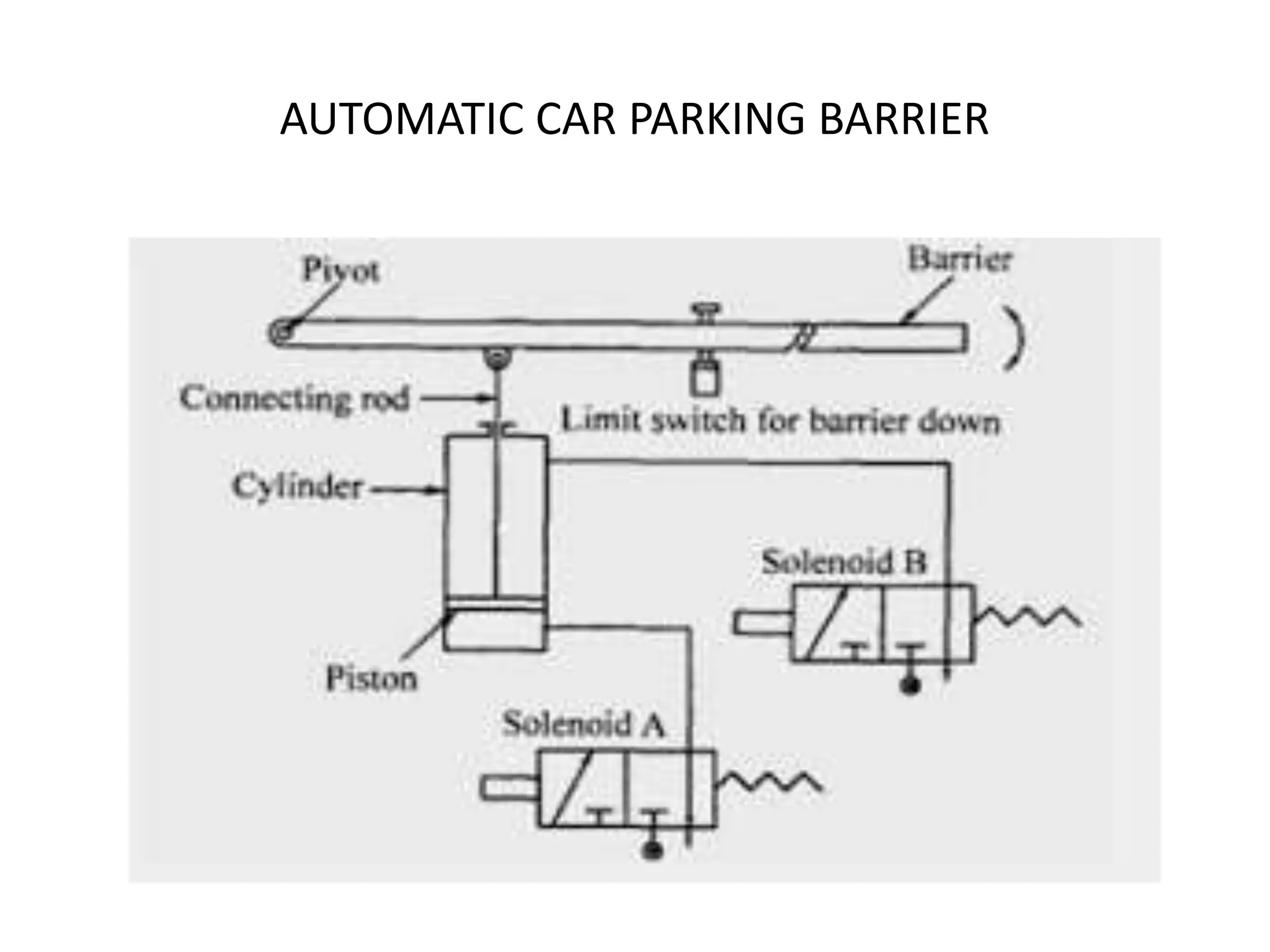
AUTOMATIC CAR PARKING
BARRIER
SYSTEM USING (PLC)
Presented by
NAME : S.ARUNKUMAR
DEPARTMENT : MECHANICAL ENGINEERING
COLLEGE : SUDHARASAN ENGG COLLEGE
WHAT ARE AUTOMATIC CAR
PARKING BARRIERS?
Introduction
• It is also known as boom barriers.
• It is a bar pivoted to allow the
• They can paired as 2Q or 4Q .
• Typically the tip of boom gate rises in a vertical arc to a
near vertical position.
• Boom gates are aften counter weigted ,so the position.
• The most common technology was used in making
electromechanical ,for its rellaiability.
• They come with 24 VDC drive and can run continuosly
for days
HISTORY
• Monday, April 13, 2015
• CAR PARK BARRIERS,COIN COUNTERS,BAR CODE READER
• The system uses a PLC for its operation.There are two barriers used namely
in barrier and out barrier. In barrier is used to open when the correct money
is inserted while out barrier open when the car is detected in front of it.It
shows a schematic arrangement of an automatic car park barrier. It consists
of a barrier which is pivoted at one end, two Solenoid valves A and B and
a piston cylinder arrangement.
•
• A connecting rod connects piston and barrier as shown in fig below
Solenoid valves are used to control the movement of the piston.Solenoid A
is used to move the piston upward inturn barrier whereas solenoid B is used
to move the piston downward.
Common components
• Power supply
• 412V DC motors
• 4 aluminium bars (500-5-2.5mm)
Automatic boom barrier can be
operated through
Push button
Remote
Rfid tag and reader
Loop deductors
Any third party access control device
AUTOMATIC CAR PARKING BARRIER
• Limit switches are used to detect the foremost position of the barrier. When current
flows through solenoid A, the piston in the cylinder moves upward and causes the
barrier to rotate about its pivot and raises to let a car through it.
COIN COUNTERS:
Coin counters which accepts mixed denomination of coins.
 The system should identify the denomination of coins through
sensors.
• The sensor output is to be interfaced to electronic circuitry that should
indicate no of coins presented and total value of coins.
• These two values must be displayed in multiplexed display.
The design is divided into two parts:
1.Mechanical design
2.Electronic design
Ladder Logic in Programmable Logic Controllers
(PLCs)
Ladder diagram, better known as ladder logic, is a
programming language used to program PLCs (programmable
logic controllers).
This article will briefly describe what ladder logic is and go
over some examples of how it functions.
PROGRAMMABLE LOGIC CONTROL
• Industrial applications. Of the various languages one can use to program a
PLC, ladder logic is the only one directly modeled after electromechanical relay
systems.
• It uses long rungs laid out between two vertical bars representing system
power. Along the rungs are contacts and coils, modeled after the contacts and
coils found on mechanical relays. The contacts act as inputs and often represent
switches or push-buttons; the coils behave as outputs such as a light or a motor.
• Outputs don't have to be physical, though, and can represent a single bit in
the PLC's memory.
• This bit can then be used later on in the code as another input. Contacts are
placed in series to represent AND logic and in parallel when using OR logic. As
with real relays, there are normally open contacts and normally closed contacts
PLC (PERFORMANCE)
 This ladder logic program is three rungs long.
 The program is “scanned” or run by the CPU from
left to right and top to bottom.
 The symbols placed throughout the rungs are actually
graphical instructions.
 The names for these instructions are:
•XIC (Examine If Closed)
•XIO (Examine If Open)
•OTE (Output Energize).
Table of content
• Ladder diagram
• Instruction list
• Structured text
• Function block diagram
• Sequential function charts
An Example of Ladder Logic
ADVANTAGES
The majority of PLCs include timer, counter, lantching, and
advanced logic instructions.
Figure shows a slightly more complicated level-control
program written by the author for an Allen-Bradley PLC.
THANK YOU
SAVE WATER

Automatic car parking barrier system using PLC

  • 1.
    AUTOMATIC CAR PARKING BARRIER SYSTEMUSING (PLC) Presented by NAME : S.ARUNKUMAR DEPARTMENT : MECHANICAL ENGINEERING COLLEGE : SUDHARASAN ENGG COLLEGE
  • 2.
    WHAT ARE AUTOMATICCAR PARKING BARRIERS?
  • 4.
    Introduction • It isalso known as boom barriers. • It is a bar pivoted to allow the • They can paired as 2Q or 4Q . • Typically the tip of boom gate rises in a vertical arc to a near vertical position. • Boom gates are aften counter weigted ,so the position. • The most common technology was used in making electromechanical ,for its rellaiability. • They come with 24 VDC drive and can run continuosly for days
  • 5.
    HISTORY • Monday, April13, 2015 • CAR PARK BARRIERS,COIN COUNTERS,BAR CODE READER • The system uses a PLC for its operation.There are two barriers used namely in barrier and out barrier. In barrier is used to open when the correct money is inserted while out barrier open when the car is detected in front of it.It shows a schematic arrangement of an automatic car park barrier. It consists of a barrier which is pivoted at one end, two Solenoid valves A and B and a piston cylinder arrangement. • • A connecting rod connects piston and barrier as shown in fig below Solenoid valves are used to control the movement of the piston.Solenoid A is used to move the piston upward inturn barrier whereas solenoid B is used to move the piston downward.
  • 6.
    Common components • Powersupply • 412V DC motors • 4 aluminium bars (500-5-2.5mm)
  • 7.
    Automatic boom barriercan be operated through Push button Remote Rfid tag and reader Loop deductors Any third party access control device
  • 8.
  • 9.
    • Limit switchesare used to detect the foremost position of the barrier. When current flows through solenoid A, the piston in the cylinder moves upward and causes the barrier to rotate about its pivot and raises to let a car through it.
  • 10.
    COIN COUNTERS: Coin counterswhich accepts mixed denomination of coins.  The system should identify the denomination of coins through sensors. • The sensor output is to be interfaced to electronic circuitry that should indicate no of coins presented and total value of coins. • These two values must be displayed in multiplexed display. The design is divided into two parts: 1.Mechanical design 2.Electronic design
  • 11.
    Ladder Logic inProgrammable Logic Controllers (PLCs) Ladder diagram, better known as ladder logic, is a programming language used to program PLCs (programmable logic controllers). This article will briefly describe what ladder logic is and go over some examples of how it functions.
  • 12.
    PROGRAMMABLE LOGIC CONTROL •Industrial applications. Of the various languages one can use to program a PLC, ladder logic is the only one directly modeled after electromechanical relay systems. • It uses long rungs laid out between two vertical bars representing system power. Along the rungs are contacts and coils, modeled after the contacts and coils found on mechanical relays. The contacts act as inputs and often represent switches or push-buttons; the coils behave as outputs such as a light or a motor. • Outputs don't have to be physical, though, and can represent a single bit in the PLC's memory. • This bit can then be used later on in the code as another input. Contacts are placed in series to represent AND logic and in parallel when using OR logic. As with real relays, there are normally open contacts and normally closed contacts
  • 13.
    PLC (PERFORMANCE)  Thisladder logic program is three rungs long.  The program is “scanned” or run by the CPU from left to right and top to bottom.  The symbols placed throughout the rungs are actually graphical instructions.  The names for these instructions are: •XIC (Examine If Closed) •XIO (Examine If Open) •OTE (Output Energize).
  • 15.
    Table of content •Ladder diagram • Instruction list • Structured text • Function block diagram • Sequential function charts
  • 18.
    An Example ofLadder Logic
  • 20.
    ADVANTAGES The majority ofPLCs include timer, counter, lantching, and advanced logic instructions. Figure shows a slightly more complicated level-control program written by the author for an Allen-Bradley PLC.
  • 21.