1. Functions of Jute Drawing
1. Drafting the finisher card sliver to a count suitable for feeding the spinning frames.
2. Reduction of weight irregularities by doubling.
3. Straightening the fibers & laying them along the sliver axis so that when they come to be
spun on the spinning frame they will be evenly drafted & twisted to form an acceptable
yarn.
Types of Jute Draw Frame
1. According to the Faller bar mechanism-
Push bar type drawing frame
Spiral drawing frame.
2. On the basis of yarn count-
a) For Hessian warp and weft & sacking warp yarns of 7 lbs/spindle & above,
First drawing frame (Push bar type).
Second drawing frame (Spiral type).
Third drawing frame (Spiral type).
b) For sacking weft yarn 20 lbs/spindle & over,
First drawing frame
Second drawing frame.
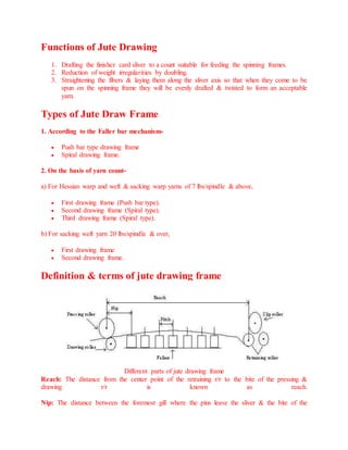
Definition & terms of jute drawing frame
Different parts of jute drawing frame
Reach: The distance from the center point of the retraining r/r to the bite of the pressing &
drawing r/r is known as reach.
Nip: The distance between the foremost gill where the pins leave the sliver & the bite of the
2. pressing & drawing r/r is known as nip.
Pitch of Faller: The distance between the one row of pins of one faller bar to pins of next faller
bar is called pitch of faller.
Lead%: The difference in the surface speed of fallers over the surface speed of retaining r/r to
give sufficient tension to the sliver is known as lead%.
Surface speed of faller – surface speed of retaining r/r
Faller bar Lead% = --------------------------------------------------------------------------------× 100
Surface Speed of Retaining r/r
Manufacturing of jute yarns: An overview
The properties such as low breaking extensibility, stiffness, messiness and long staple fibre
differentiate the manufacturing of jute yarn from cotton system, say N Kundu and P Y
Verma, who give an insight into the jute spinning system.
The main functions of jute spinning units are to convert jute
fibres to yarns for different end uses. The types of jute yarn
manufactured can be classified according to the
application/use to which they are put ie, fine yarns, hessian
yarns, carpet, sacking yarns, etc. These yarns can be further
classified into warp and weft yarns, the warp yarns normally
being superior to the weft yarns as they have to withstand the
cycles of stress during weaving while the weft yarns act more
as filler and undergo less strain during weaving process.
Jute yarns of various dimensions are plied together to make twines, ropes, cordages, etc as
per requirement and use. These are used for the purpose of tying, knotting, binding, etc
particularly agricultural commodities.
It is not possible to produce jute yarn finer than 138 tex (4 lb/spy) by conventional
techniques. But, later on after development of apron draft ring spinning system it is easier to
produce yarn as fine as 60 tex (1.75 lb/spy). This type of jute yarn has the prospect of being
used in high quality jute textiles.
The range of yarns spun from jute is given in Table below:
3. The processing sequence in jute spinning is
Selection
Raw jute reeds after retting and drying are packed in the form
of bales of 150 kg or 180 kg for easy transportation to jute
mills. The bales from the mills godown are taken to the
selection section where all the jute bales are opened to find out any defect and to remove the
defective portion from the morah by experienced workers. The bales are assorted according
to end use like hessian weft, sacking wrap, sacking weft, etc. After selection, jute bales are
carried to softening/batching section by workers.
Softening section/Batching section
The process of adding oil and water emulsion on jute batches is called as batching. The stack
of fibre blends from different types of jute for a particular class of yarn is called a batch. The
department where the jute is prepared for carding is called the batching house. In this section
the fibres are conditioned by adding oil and water to it for easy processing in consequent
processes. For making the jute fibre bundles suitable for next carding operation the morah
prepared in selection are processed through softener or spreader machine. During its passage
through these machines, oil in water emulsion is applied on jute for its moistening or
lubrication.
Jute batching emulsion
Jute batching emulsion usually contains the mineral oil, water and an emulsifier. The
commonly used mineral oil is Jute batching oil (JBO), a middle distillate produced by
petroleum refineries. JBO lubricates the fibre and makes it pliable. Water provides sufficient
dampness to the fibre and increases its extensibility. The emulsifier reduces the surface
tension and stabilises the emulsion. The emulsion solution can be prepared by using 20 -
4. 30% water, 2 - 5% JBO and 0.1 - 0.5% emulsifying agent on the weight of fibre depending
upon the humidity condition. The processing of jute through spreader or softener machine
with emulsion application and subsequent piling of about 24 - 48 hours weakens the joints of
the meshy structure for easy longitudinal splitting in the carding operation. During piling oil
and water migrates through the fibre mass and "Thermo fillic" action take place by bacterial
fermentation which softens the hard portion of the root.
Spreader
In this machine the jute reeds are assembled into a continuous
sliver. The reeds pass between a pair of fluted feed rollers
and on to the pins of slow moving coarse pinned lattice
known as slow chain; above the slow chain there are two or
three lantern rollers to trace the jute firmly down on to the pins. Half way along the machine
the material is transferred from slow chain to similar type fine pinned lattice fast chain.
Because of the greater linear speed of the fast chain the jute is combed and drafted at the
transfer point. After crossing over the fast chain, the jute passes between a pair of fluted
drawing rollers and is guided down a conductor channel where the emulsion is added, either
by a pressure tray or by a gravity – fed drip weir. The final action is to collect the sliver in
compact roll form suitable for carding. Draft range lies between 10 - 11. Figure 1 shows the
schematic diagram of a spreader machine.
Softener
Industrially softener machine is used for batching of sacking yarns, the raw materials of
which are lower grade. It is a long machine comprising 64 - 72 pairs of cast iron fluted
rollers. The lower of the pair is driven by side shaft and the upper is spring loaded one by
contact with the lower of the pair.
Figure shows the schematic diagram of jute softener machine.
Functions of softener:
The jute is flexed between two pair of rollers and is made softer, some of loose dust
and dirt falls off and pieces of bark and stick broken making them easier to remove at
later stage.
The emulsion solution is dripped onto the jute through a simple gravity fed weir
about one third of its way along the rollers.
The sump beneath the rollers collect the excess amount of emulsion solution passed
through the rollers and through the fibres and these excess solution is pumped back
through various filters.
After softening the longer jute (after cutting the heavy barky root end) is conditioned
for 24 - 48 hours and is then ready for feeding to breaker card.
Carding
5. The primary objectives of jute carding are:
a) To split the jute reeds longitudinally and break it transversely.
b) To convert the reeds of jute into a uniform fibrous strand, sliver suitable for further
processing.
c) To clean, orient and attenuate the fibre to some extent.
d) To randomise the fibres among themselves.
In jute processing generally two carding machines are used breaker and finisher and these are
roller and clearer type.
Breaker card
The breaker cards are commonly down striking and half circular ie, the cylinder pins strike
downward the fibre feed from the top and the fibres travel half way round the cylinder. It is a
very important machine in jute processing system because it determines the average fibre
length and fineness which affects yarn quality. It has two pairs of workers and strippers.
Figure 3 shows the sketch of one such machine.
Normally 6 - 8 spreader roll slivers are fed onto the feed sheet from a creel at floor level and
the material passes over up towards the 'shell' feed. The shell feed system consists of a
pinned roller with backward facing pins and a cast iron shell which is shaped to follow the
circumference of both feed roller and the main cylinder, through which the jute enters and
travels towards the fast moving cylinder comb, split and convert the jute reeds into a fibrous
mass. The fast moving pins of cylinder progressively. The clearance between the shell and
the feed roller and cylinder and also the rate of fibre feeding have a considerable influence on
the average fibre length in the card sliver.
After shell feed operation, the jute reeds come into the real carding action carried out by two
pairs of workers and strippers. The essential features of this worker and stripper action are
combing, teasing, spitting as the fibre is transferred from the cylinder to worker, then from
the worker to stripper and finally from the stripper back to the cylinder. Since the pins of
cylinder and worker are point to point arrangement and surface speed of cylinder is very
higher than the worker, the top layered fibres are arrested by the 1st worker pins and the
remaining fibres firmly held by the cylinder come into action of next worker stripper action.
Due to the two pairs of worker and stripper action the fibre networks are gradually split into
fibrous mass and in addition there is some degree of mixing inside the card as some of the
material is held back and deposited on top of fresh. Indeed, it is possible for a bunch of fibres
to travel several times round the worker stripper pair before it passes on with the cylinder.
The tin roller below the worker and stripper pair reduces the amount of fall-out of the fibrous
mass below the card.
After leaving the 2nd worker stripper pair the jute meets the doffer whose function is to strip
the jute off the cylinder and pass it to the nip of drawing rollers whose surface speed is about
twice that of doffer. However, doffer removes a major portion of the fibre mass on the
6. cylinder while the rest travels round with the cylinder. The fibre is caught as a thin and
consistent web in the nip of the drawing roller and the doffer pins. The web emerges from the
drawing nip and passes down a V or U shaped sheet metal condenser and a pair of heavily
loaded delivery roller to compress the jute into a compact sliver.
Typical parameters
Feed roller diameter: 10.6"
Cylinder diameter: 48"
Stripper and worker diameter: 10.6 inches
Doffer diameter: 21.3"
Cylinder Speed: 200 rpm
No of doublings: 6 - 8 spreader rolls
Draft: 10 - 25
Sliver count: 18 - 26 lb/100yds (90 - 130 ktex)
Finisher card
Figure 4 shows the lay out of a finisher card suitable for hessian, carpet and sacking warp
yarns.
The machine is designed as 4.5 pairs, full circular, double doffer and down striking. The
roller and cylinder are pinned in the same manner as the breaker card but some what finer
and closer together. The commonest type of feed arrangement is the pinned plain roller feed
suitable for hessian and carpet quality and sacking warp cards. In the pinned plain feed the
feed roller is clothed with pins but the roller immediately above it is not.
The action of more number of workers and strippers in the finisher is same as in the breaker
and therefore the finisher continues the work of drafting, doubling, splitting the fibre
networks and cleaning. For coarser variety of jute, one more carding passage called 'Inter
card' is provided between breaker and finisher cards for better splitting and opening of jute.
In some of the finisher card, there may be a short of drawing head attachment comprising a
pair of feed rollers, a short lattice of pin bars and a pair of delivery rollers. Whenever the
sliver passes through it, the pinned lattice controls the fibre movement.
Typical parameters
Feed roller diameter: 6.4"
Feed stripper: 6.4"
Cylinder diameter: 48"
Stripper and worker diameter: 10.6 inches
Doffer diameter: 21.3"
Cylinder Speed: 200 rpm
No of doublings: 8 - 12
Draft: 10 - 20
7. Sliver count: 13 - 18 lb/100yds (65 - 90 Ktex)
Draw frame
The primary objectives of jute draw frame are:
1. Drafting the finisher card slivers to count suitable for feeding the spinning frame.
2. Doubling the slivers to minimise the irregularities.
3. Straightening and paralleling of the fibres along the sliver axis.
Figure 5 shows the general outline of the drafting mechanism of a jute drawing frame. The
slivers feed through two retaining rollers and a self weighted jockey roller and then pass
through the gill pins. The gill pins are carried on a series of faller bars which move forward
and follows a rotational path. As the slivers leave the nip of the back retaining roll, a faller
bar with its sharp pins strike upwards into it and the slivers are carried forward to the front of
the machine in a controlled manner like a continuous layer over the faller bars. When the
faller bars are close to the drawing rollers they
drop out of the sliver and travel back
underneath the sliver in preparation for
another strike upwards. The relative surface
speed of the drawing roller and retaining roller
determines the draft. The linear speed of the
gill pinned fallers is 10 to 15% higher than
that of retaining rollers to maintain the
required tension and is known as lead%.
The distance between the centre of the front retaining roller to the nip of the drawing and
pressing roller is called the reach of the drawing frame. It should be slightly longer than the
longest fibre in the sliver. It generally lies between 14 to 16 inches. If reach is less, longer
fibre will break, more waste will generate and irregular sliver will produce. If reach is higher,
there will be no control on the loose and short fibres, so produce irregular sliver.
Doubling may be carried out by placing two or more slivers together at the feed end of the
machine and entering them on to one set gill pins or by placing individual slivers on each set
pins and uniting the slivers as they emerge from the nip of the drawing rollers. The former
situation holds for the lighter slivers at the last drawing passage and in the later situation
doubling takes place at front of the machine through the doubling plate.
The doubling plate is a cast iron plate having slots with rounded edges at an angle of 45° to
the line of the frame through which the sliver can pass so as to change their direction. In this
doublings one sliver comes straight and the other slivers are turned through 45° and pass
along the back of the plate to anther 45° slot. When they pass through the second slot they
are laid down on top of one another and travel towards the delivery roller where they are
consolidated into one sliver and leave the machine.
Jute drawing frames are divided into two types, depending on the mechanism of faller bars.
8. 1. Push bar type:
In this type of draw frame, in between the retaining and drawing rollers there are two carrier
wheel shafts which drive the faller bars. The bars move forward on the slide driven by the
teeth of the carrier wheel. The fallers have specially designed crank ends which run in slides
on the machine frame. The bars bear across the full width, the bar behind pushing the bar in
front. The carrier wheel has half as many teeth as there are faller bars, alternate bars being
driven from opposite side of the machine.
2. Spiral or Screw gill type:
In this type there are two spiral screws on each side, one set directly above the other. The
ends of each faller bar are cut to fit into the grooves on the spirals so that as the screws rotate
they drive the faller bars along. As each faller bar comes to the end of the top screw it is
knocked down on the bottom one by a cam on the top screw, springs holding it steady as it
falls into the grooves of the bottom screw . The bottom spiral is more coarsely pitched than
the top one so that the faller bars are returned quickly to the back of the machine ready to be
lifted by cams on the bottom screw up into the spirals of the top screw. By having a coarse
spiral on the bottom fewer bars are needed to complete the gill sheet.
The common arrangement for hessian qualities is to have three drawing passages over a first
pushbar, a second double thread spiral and a finisher triple thread spiral drawing. The double
thread and triple thread are designed to increase the speed of the faller bars. The differences
between the push bar type draw frame and spiral type draw frame are as shown in the Table
below.
As the sliver becomes finer in its passage through the drawing stages the coherence between
the fibres gradually decreases. It is difficult to handle and also carry up the back of the
spinning frame. To overcome this, the sliver is crimped by the crimping box attached to the
delivery of the draw frame to insert certain amount of cohesion to the strand. The sliver
leaves the nip of the drafting roller and passes down the sliver plate into the nip of a pair of
9. fluted delivery rollers, the upper one being spring loaded and positively driven through a
wide pitch gear from the lower one.
The sliver is driven into the box where it meets a metal finger hanging down into the box.
The finger blocks the motion of the sliver and fills the box quickly. When more slivers enters
at the back the lid of the box is forced to open and the crimped sliver exits. These slivers are
then collected in the cans which rest on can turning plates at the front of the machine and
packed with the help of the up and down movement of the can tramping arms attached with
the frames one for each delivery.
Spinning
The majority of jute yarns are spun from finisher drawing sliver and spinning from roving is
confined chiefly to finer counts (173 tex or 5lb/sp less) of yarns. But now days mostly ring
spinning is used for fine count yarns directly from slivers. Jute spinning frames (flyer
spinning) are designated by the pitch (distance between adjacent spindles). The main
objectives of spinning process are drafting, twisting and winding.
Drafting
All jute spinning frames have two sets of rollers along the
length of the machine –the retaining roller and the drawing
roller. In each set one roller is positively driven and the other
roller is the pressing member to grip the fibres in between.
Depending upon the draft control, jute spinning frames can
be classified into following types.
1. Slip draft system (Figure 6): This draft system is used in
4¼ inch or in 4¾ inch pitch spinning frame. It consists of a
semi-circular type breast plate having upward concave and a
pair of deeply grooved intermediate rollers for control of
short fibre movement in between retaining roller and drawing
rollers. It's draft range lies between 10 - 22 and it can spin
medium to coarse count yarns (8lb/sp to 28lb/sp) depending
upon the pitch of the frame.
2. Apron draft system(Figure 7): This draft system is used
in 4¼ inch pitch spinning frame. It consists of either two
rubber aprons or bottom rubber apron with top metallic plate
in between the retaining and drawing rollers for better short
10. fibre control. Its draft range lies between 10 - 22 and it can spin fine count yarns (4 lb/sp to 8
lb/sp).
3. V roller (groove) draft system (Figure 8): This draft system is
used in 5½ inch pitch spinning frame. It consists of a series of
intermediate rollers, each of which has a deep groove cut in its face.
In between the retaining roller and drawing roller. Its draft range lies
between 4.5 to 10.5 and suitable for coarser counts (18 lb/sp to 50
lb/sp).
Twisting
Jute spinning frame inserts the twist by means of overhung flyers,
either two legged flyer or Baxter flyer, suspended above the
bobbins. The flyers are carried on ball bearing wharves mounted on
the front of the frame. The part of the wharf projecting above the mounting assembly is
called the cap and the part below the assembly is called the crown, which is driven by cotton
or nylon tape from the main cylinder of t he machine. Here the flyer is positively driven and
the bobbin is driven by the yarn pull.
The yarn passes from the nip of the drawing rollers to the wharf cap and continues through
the wharf up to the flyer eye at the bottom of the leg and then winds on to the bobbin. The
simplest relationship between flyer speed, delivery speed and twist is,
Twist per inch = Flyer speed (rpm)/Front roller delivery (inches/min)
This equation can be modified depending upon twist take up (2 or 2½% in jute yarn) as
follows
TPI = (Spindle speed in rpm/ FR delivery in inches/minute) x (100+T)/100
Where T = Take up% = (Untwisted length-twisted length) x 100/Untwisted length.
Twist in yarn is generated by the rotation of the flyer and ascends from below into the upper
portion of the yarn towards the drawing nip. The twist angle or the twist factor remains
constant throughout the length of the yarn. The thinner parts of the yarn have more turns per
unit length than that of thicker one.
Twist factor = Twist per inch x √Grist
Common twist factors:
11. Winding on
The bobbins rotate around central dead spindles which are set vertically in the builder. As the
builder moves up and down the bobbins alternately rise into and withdraw from the flyers
and this reciprocating movement, combined with the rotation of the flyers about the bobbins,
winds the yarn on the bobbin in a continuous spiral. When the builder is at the top of its
traverse the yarn is winding on at the bottom of the bobbin and vice versa.
The following equation corresponds the correct winding.
nfly - nbo = L/pd
Where nfly = flyer rpm, nbo = bobbin rpm, L = delivery speed, d = bobbin diameter.
The implication of the relationship is that as the bobbin fills, d becomes greater and the
difference between flyer speed and bobbin speed decrease. As the flyer speed remains
constant, the bobbin speed must increase. It is attended automatically by the bobbins
themselves as a result of the manner in which they are rotated by the yarn.
12. References
1. www.jute.org.
2. Atkinson R R: Jute - Fibre to Yarn, 1964.
3. Mukherjee A and Ray P: Mechanical Processing of Jute, (Jute Basics-IJSG), 2010.
4. Paul S K: Comprehensive Study in Modern Jute Technology, 1960.