Article: Heat Staking Metal Inserts with Induction
•
1 like•646 views

Read an informative article on using induction heating for heat staking metal inserts. The article was written by Dr. Girish Dahake, Senior Vice President of Global Applications for Ambrell Precision Induction Heating.

Recommended
Recommended
More Related Content
What's hot
What's hot (14)
Viewers also liked
Viewers also liked (20)
Similar to Article: Heat Staking Metal Inserts with Induction
Similar to Article: Heat Staking Metal Inserts with Induction (20)
Recently uploaded
Recently uploaded (20)
Article: Heat Staking Metal Inserts with Induction
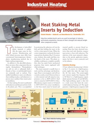
- 1. he development of glass-filled plastic materials is undeni- ably the major cause for this increase. Manufacturing and other related processes must differ from conventional lower-temperature thermo- plastic manufacturing methods due to higher melting temperatures. In addition to the glass-filled plastics, there are many other components that use regular thermoplastics. Thermoplastics are still too soft to sufficiently hold a thread, so brass- or steel-threaded inserts are commonly used as anchors. Post- molded installation is more cost effective than molding in place, and induction is a proven way to preheat these inserts prior to installation. For heat staking, the insert is preheated withinductionandthenpressedintoahole in the plastic part. This is accomplished by positioning the induction coil over the hole and then holding the insert in the coil for a short period of time. When the correct temperature is achieved, the insert is pressed into the plastic (Fig. 1). A narrow zone of plastic then melts and flows into the knurls of the insert. The plastic re- solidifies, resulting in a complete assembly that often has much better mechanical properties than inserts implanted with other techniques. The insert material is usually brass or steel; each has advantages and disadvan- tages. Brass is non-magnetic and will not corrode as easily as steel. However, brass is a softer material and will anneal at tem- peratures as low as 450˚F (232˚C). Steel starts to anneal at 1200˚F (650˚C). Glass- filled plastics require inserts to be heated to 700˚F (371˚C) for correct installation, so the brass inserts must be heated and inserted quickly to prevent thread an- nealing. Brass has lower electrical resis- tivity than steel and, therefore, requires more power to heat with induction. The selection of the insert material is depen- dent on the specific application require- ments, but brass is most commonly used in the industry. Induction Heating A basic induction heating setup is shown in Fig 2. It consists of a high-frequency power supply that takes the input from the AC line mains. This power-supply unit converts regular line frequency (50 or 60 Hertz) to a high-frequency signal, which operates between 10 and 400 kHz. This high-oscillating signal is then fed to a tank circuit that feeds the water- cooled induction heating coil. The signal generates a high-frequency magnetic field Heat Staking Metal Inserts by Induction Girish Dahake – Ambrell, an Ameritherm Co.; Scottsville, N.Y. Injection-molded plastic parts are used increasingly in industry, particularly automotive, because of their strength and reduced weight when compared to metal. Fig.5. Four-position insert heating coil h p TT Fig.1. Typical heat insertion process Fig.2. Basic induction heating system Feedback control system Coil connection Coil Part Fixture Water Air-operated cylinders Coil Insert Insert Plastic part Non-magnetic stainless-steel push rods AC line Tank circuit Power supply Smaller sources of variation Larger sources of variation Featured in Industrial Heating May 2014
- 2. FEATURE | Induction Heating inside the induction coil. The insert is placed inside this induction heating coil. It generates eddy currents due to the high-frequency magnetic field and produces heat. An optional noncontact temperature controller can be used to measure the temperature of the insert. Its output can then be fed to the induction heating power supply to control the temperature of the insert for each cycle. Here are the critical parameters for a consistent induction insertion process. • Tuning frequency: The frequency of operation of the power supply should be chosen to deliver efficient energy based on the size and material of the part. Care must be taken to ensure that this frequency is above the critical fre- quency of the part for efficient heating. • Repeatability of the induction power supply: This is the cycle-to-cycle repeatability of the induction power supply in manufacturing given standard incoming voltage variations and other tolerances. • Heat-on time: This should be the same every cycle to reach the same temperature on the insert. • Positioning of the insert in the coil: This is dependent on the fixturing and handling device. Varying placement of the insert inside the induction coil will result in inconsistent temperatures of the insert. • Insertion pressure: The location of the insert in the hole of the plastic part is determined by insert pressure. Lower pressure leaves the insert above the required location, whereas higher insertion pressure may cause undesirable “flash” of the plastic material. • Fit of the insert in the thermoplastic material: The diameter of the insert hole must be the correct size to allow the plastic to flow around the insert. If the hole is too small, extra plastic will be displaced. • Cool-down time: Cool down following the insertion cycle is needed to anchor the insert inside the plastic part. If the cool-down time is too short and the insertion pressure is removed quickly, inserts will often be pushed out of the plastic part. • Insert temperature: The installation temperature of the insert is a key factor in the success of the staking process. Each insert must be heated to the same temperature in the same time to achieve a consistent process. Single-Position vs. Multiple- Position Coil The simplest system consists of a single- Non-magnetic stainless steel pushrod Air-operated non-magnetic steel push rod Computer- controlled "X" and "Y" table Remote heat station with coil Plastic Part X Y Remote heat station 3-position multiturn coil Steel inserts Induction Heating Benefits/Advantages Unsurpassed reliability: 100% solid-state RF power and control circuitry. Process repeatability: With advanced microprocessor control, power supplies are extremely accurate and repeatable. Maximum deliverable power: High-frequency range and continuous auto tuning of the power supplies track the resonant frequency of the system to continuously deliver power at resonance. Convenient coil placement: Remote heat stations can be located on the production line, up to 200 feet from the power supply (application-dependent). Easy system integration: Quick and easy integration manufacturing control with PLC and analog inputs. Fig.3. Single-position heating system Fig.4. Multiple-position heating system
- 3. position heating coil to heat one insert at a time. Depending on the number of inserts in the plastic part, either the plastic part can be indexed under the induction coil or the heating head can be moved to each in- sert location. An x-y positioning table can be used in conjunction with a single-posi- tion coil when multiple inserts need to be installed in a single molded part. The posi- tion of the coil is held constant, and the x-y table moves each insert location under or above the coil. This technique provides for a flexible manufacturing tool that can be changed by software programming rather than hardware tooling changes. A second option for a single-position coil is the use of a robotic arm. The plas- tic part is held in a fixed location while the coil and indexing mechanism can be moved to each insert location. Location of the coil relative to the heat station is custom-designed for each application (Fig. 3). A multiple-position coil makes it possible to install more than one insert at a time into a single plastic part (Fig. 4). Three- and four-position coils have been used for this application. The coil is normally in a fixed position, and the plastic part is placed under the coil. The inserts for each location are heated simultaneously and then pressed into the plastic. The multi-position coil requires a higher power than a single-position coil. However, the production cycle time is significantly shorter. Case Study A four-position induction heating coil (Fig. 5 - intro) is used to heat four brass inserts of 8 mm diameter to 550˚F (290˚C) using the Ambrell EasyHeat 7590, a 7.5- kW induction heating power supply. The inserts are heated to temperature within four seconds before they are pushed into the plastic part. The induction coil is designed to allow for adjustment of each heating location so as to heat the four inserts to exactly the same temperature. The temperature variation between the four positions of the induction coil, once adjusted, is locked to ensure good product. Figure 6 shows the thermal image of the four inserts at the end of the heating cycle. Conclusion Whether applied directly in an initial design or incorporated into an existing process or industrial heating operation, induction heating has become more and more desirable because of its ability to contribute to lean-manufacturing setups. It is easy to justify a good value proposition for the induction heating setup. Its flexibility, small size, versatility and efficiency represent an indispensable adjunct for a number of process heating applications in manufacturing processes worldwide. IH For more information: Dr. Girish Dahake, Ph.D.,istheVP,GlobalApplicationsforAmbrell Inc., an Ameritherm Co., 39 Main Street, Scottsville, NY 14546; tel: 585-889-9000 (X 121); fax: 585-889-4030; e-mail: gdahake@ ambrell.com; web: www.ameritherm.com Fig.6. Thermal image of the four inserts at the end of the heating cycle
- 4. staking.ambrell.com 411-0170-00 Rev A Ambrell Power Supplies Ambrell manufactures a wide range of power supplies, both low and high power for an array of applications. For heat staking, the EASYHEAT (1-10 kW) and the low power end of the EKOHEAT (10-15 kW) product lines are most popular. Ambrell power supplies have movable workheads so the coil can be placed a distance from the power supply, a high power factor to ensure efficient heating, significant versatility with multiple capacitor and tap configurations, and repeatable, reliable heating with agile frequency tuning. Additionally, systems are compact and easy-to- integrate into manufacturing processes. Systems are manufactured at Ambrell’s ISO 9001:2008 certified facility at its headquarters in Scottsville, NY USA. Complimentary Applications Testing You can send parts to Ambrell’s Applications Laboratory for a free half-day of testing. Testing is recorded and parts are sent back to you for inspection. Additionally, you are welcome to visit during testing to see induction heat staking live. After testing, you will receive a tailored system recommendation. The recommendation will be based on your process requirements, including process time, cycle time and temperature. Heat staking is a common application at Ambrell. So take advantage of that expertise and send in your parts for risk- free applications testing today. As a pioneer in solid-state induction heating technology, with over 25-years of innovation, Ambrell provides industry- leading heating solutions. We pride ourselves in making it easy for you to implement an efficient, safe, rapid induction heating process by applying our knowledge of the science and art of induction to your heating application. Ambrell is headquartered in the United States with worldwide operations including Ambrell Ltd. in the United Kingdom, Ambrell SARL in France and Ambrell B.V. in the Netherlands. About Ambrell Ambrell Corporate 39 Main Street Scottsville, NY 14546 tel: +1 585 889 9000 fax: +1 585 889 4030 sales@ambrell.com Ambrell B. V. Holtersweg 1 7556 BS Hengelo The Netherlands Tel: +31 (0)880 150 100 Fax: +31 (0)548 659 010 saleseu@ambrell.com Ambrell, Ltd. Phoenix Works, Saxon Way Battledown Industrial Estate Cheltenham, Gloucestershire GL52 6RU tel: +44 (0)1242 514042 fax: +44 (0)1242 224146 salesuk@ambrell.com Ambrell SARL Tour Sébastopol 3 quai Kléber 67000 Strasbourg France Tel: +33 970 440 335 Fax: +33 38 9748533 saleseu@ambrell.com