More Related Content
Similar to 2 pumps part 2 including centrifugal pumps rev 4 (19)
2 pumps part 2 including centrifugal pumps rev 4
- 1. © 2003 General Physics Corporation ABC / Mechanical Science / Chapter 2 / / Rev 2
ACADBasics@gpworldwide.com
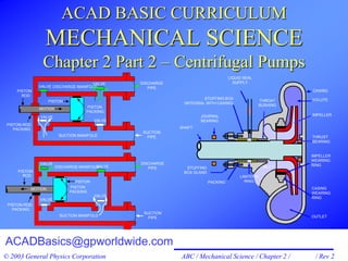
ACAD BASIC CURRICULUM
MECHANICAL SCIENCE
Chapter 2 Part 2 – Centrifugal Pumps
PISTON
ROD
VALVE
VALVE
VALVE
PISTON
PACKING
PISTON
DISCHARGE MANIFOLD
SUCTION MANIFOLD
PISTON-ROD
PACKING
MOTION
SUCTION
PIPE
DISCHARGE
PIPE
PISTON
ROD
VALVE
VALVE
VALVE
VALVE
PISTON
PACKING
PISTON
DISCHARGE MANIFOLD
SUCTION MANIFOLD
PISTON-ROD
PACKING
MOTION
SUCTION
PIPE
DISCHARGE
PIPE
VALVE
IMPELLER
WEARING
RINGINLET
LANTERN
RINGPACKING
STUFFING
BOX GLAND
SHAFT
JOURNAL
BEARING
STUFFING BOX
(INTEGRAL WITH CASING)
LIQUID SEAL
SUPPLY
THROAT
BUSHING
CASING
VOLUTE
IMPELLER
THRUST
BEARING
OUTLET
CASING
WEARING
RING
- 2. © 2003 General Physics Corporation
PUMP CLASSIFICATIONS
PUMPS
Kinetic
(Dynamic)
Positive
Displacement
Part 1
Part 2
- 3. © 2003 General Physics Corporation ABC / Mechanical Science / Chapter 2 / TP 2 - 2 / Rev 02
OBJECTIVES
12. STATE the purpose of the following centrifugal pump components:
a. Casing e. Bearings
b. Gaskets f. Seal rings
c. Impeller g. Volute
d. Shaft h. Shaft seals
13. DESCRIBE the operation of the following types of centrifugal
pumps:
a. Volute and diffuser pumps
b. Radial-flow, axial-flow and mixed-flow pumps
14. DESCRIBE the operation of centrifugal pumps, including
requirements for the following:
a. NPSH
b. Starting a centrifugal pump
c. Operation with a centrifugal pump dead headed
d. Minimum flow
e. Prevention of runout
Part 2 has 12 objectives.
- 4. © 2003 General Physics Corporation ABC / Mechanical Science / Chapter 2 / TP 2 - 3 / Rev 02
OBJECTIVES
15. STATE the relationship between pump load, motor current, speed,
flow, pressure, and power for a centrifugal pump.
16. EXPLAIN the three centrifugal pump laws.
17. DETERMINE the effects of changes for a centrifugal pump in flow,
pump speed, or system characteristic curve on the system
operating point.
18. DESCRIBE pump shutoff head and runout, including definitions,
causes, effects on centrifugal pump operation, and methods of
prevention.
19. DRAW and LABEL characteristic curves for centrifugal pumps.
- 5. © 2003 General Physics Corporation ABC / Mechanical Science / Chapter 2 / TP 2 - 4 / Rev 02
OBJECTIVES
20. DESCRIBE the shape of the characteristic curves for the following
centrifugal pump operating modes:
a. One pump in slow speed
b. One pump in fast speed
c. Two pumps in parallel
d. Two pumps in series
21. DESCRIBE the operation of centrifugal pumps in series and in
parallel arrangements.
22. DESCRIBE the operation of jet pumps.
23. DESCRIBE what items are included in post maintenance testing.
24. IDENTIFY and DESCRIBE auxiliary support equipment associated
with pumps. [Not included in Mechanical Technology I]
- 6. © 2003 General Physics Corporation ABC / Mechanical Science / Chapter 2 / TP 2 - 5 / Rev 02
CENTRIFUGAL PUMP
DISCHARGE
IMPELLER
VANES
EYE
IMPELLER
WEARING
RING
INLET
LANTERN
RINGPACKING
STUFFING
BOX GLAND
SHAFT
JOURNAL
BEARING
STUFFING BOX
(INTEGRAL WITH CASING)
LIQUID SEAL
SUPPLY
CASING
VOLUTE
IMPELLER
THRUST
BEARING
OUTLET
CASING
WEARING
RING
Fig 2-29
Most common pump used in industry.
- 7. © 2003 General Physics Corporation ABC / Mechanical Science / Chapter 2 / TP 2 - 6 / Rev 02
CENTRIFUGAL PUMP
DISCHARGE
IMPELLER
VANES
EYE
Fig 2-29
• Centrifugal force is the outward
force.
• Centrifugal pumps turn kinetic
energy into flow energy (pressure).
• Wide range of pressures and flow
rates.
• Basic process:
Shaft (driven by motor)
Fluid enters the suction eye
Impeller pushes the water and
increases its speed
Water moves outward moving
very fast
The volute widens and KE is
turned into pressure.
- 8. © 2003 General Physics Corporation
CENTRIFUGAL PUMP
IMPELLER
WEARING
RING
INLET
LANTERN
RINGPACKING
STUFFING
BOX GLAND
SHAFT
JOURNAL
BEARING
STUFFING BOX
(INTEGRAL WITH CASING)
LIQUID SEAL
SUPPLY
THROAT
BUSHING
CASING
VOLUTE
IMPELLER
THRUST
BEARING
OUTLET
CASING
WEARING
RING
Fig 2-29
Objective 12. STATE the purpose of the
following centrifugal pump components:
a. Casing
b. Gaskets
c. Impeller
d. Shaft
e. Bearings
f. Seal rings
g. Volute
h. Shaft seals
- 9. © 2003 General Physics Corporation ABC / Mechanical Science / Chapter 2 / TP 2 - 8 / Rev 02
CENTRIFUGAL PUMP
IMPELLER
WEARING
RING
INLET
LANTERN
RINGPACKING
STUFFING
BOX GLAND
SHAFT
JOURNAL
BEARING
STUFFING BOX
(INTEGRAL WITH CASING)
LIQUID SEAL
SUPPLY
THROAT
BUSHING
CASING
VOLUTE
IMPELLER
THRUST
BEARING
OUTLET
CASING
WEARING
RING
Fig 2-29
8 major components of a centrifugal pump:
• Casing
• Gaskets
• Impeller
• Shaft
• Bearings
• Seal rings
• Volute
• Shaft seals
Objective 12
- 10. © 2003 General Physics Corporation ABC / Mechanical Science / Chapter 2 / TP 2 - 9 / Rev 02
CENTRIFUGAL PUMP
IMPELLER
WEARING
RING
INLET
LANTERN
RINGPACKING
STUFFING
BOX GLAND
SHAFT
JOURNAL
BEARING
STUFFING BOX
(INTEGRAL WITH CASING)
LIQUID SEAL
SUPPLY
THROAT
BUSHING
CASING
VOLUTE
IMPELLER
THRUST
BEARING
OUTLET
CASING
WEARING
RING
Fig 2-29
Casing
• The pump casing
houses the majority of
the major pump
components.
• The inlet (suction)
and outlet (discharge)
connections are
integral to the pump
casing.
Objective 12a
- 11. © 2003 General Physics Corporation ABC / Mechanical Science / Chapter 2 / TP 2 - 10 / Rev 02
CENTRIFUGAL PUMP
IMPELLER
WEARING
RING
INLET
LANTERN
RINGPACKING
STUFFING
BOX GLAND
SHAFT
JOURNAL
BEARING
STUFFING BOX
(INTEGRAL WITH CASING)
LIQUID SEAL
SUPPLY
THROAT
BUSHING
CASING
VOLUTE
IMPELLER
THRUST
BEARING
OUTLET
CASING
WEARING
RING
Fig 2-29
Casing
• The faces of the
casing are machined
to fit together
smoothly, but the
finest machining still
has some leakage.
Objective 12a
- 12. © 2003 General Physics Corporation ABC / Mechanical Science / Chapter 2 / TP 2 - 11 / Rev 02
CENTRIFUGAL PUMP
IMPELLER
WEARING
RING
INLET
LANTERN
RINGPACKING
STUFFING
BOX GLAND
SHAFT
JOURNAL
BEARING
STUFFING BOX
(INTEGRAL WITH CASING)
LIQUID SEAL
SUPPLY
THROAT
BUSHING
CASING
VOLUTE
IMPELLER
THRUST
BEARING
OUTLET
CASING
WEARING
RING
Fig 2-29
Casing
• The faces of the
casing are machined
to fit together
smoothly, but the
finest machining still
has some leakage.
• Gaskets are used to
reduce leakage
• Gaskets are semi-soft
flexible materials
used to seal mating
surfaces or flanges.
Objective 12ab
- 13. © 2003 General Physics Corporation ABC / Mechanical Science / Chapter 2 / TP 2 - 12 / Rev 02
CENTRIFUGAL PUMP
IMPELLER
WEARING
RING
INLET
LANTERN
RINGPACKING
STUFFING
BOX GLAND
SHAFT
JOURNAL
BEARING
STUFFING BOX
(INTEGRAL WITH CASING)
LIQUID SEAL
SUPPLY
THROAT
BUSHING
CASING
VOLUTE
IMPELLER
THRUST
BEARING
OUTLET
CASING
WEARING
RING
Fig 2-29
Impeller
• The impeller is the
rotating component of
the pump that
converts the
mechanical energy of
the prime mover (the
pump motor) into
kinetic energy
(velocity) in the fluid.
• The impeller is
mounted on the pump
Shaft.
Objective 12c
- 14. © 2003 General Physics Corporation ABC / Mechanical Science / Chapter 2 / TP 2 - 13 / Rev 02
CENTRIFUGAL PUMP
IMPELLER
WEARING
RING
INLET
LANTERN
RINGPACKING
STUFFING
BOX GLAND
SHAFT
JOURNAL
BEARING
STUFFING BOX
(INTEGRAL WITH CASING)
LIQUID SEAL
SUPPLY
THROAT
BUSHING
CASING
VOLUTE
IMPELLER
THRUST
BEARING
OUTLET
CASING
WEARING
RING
Fig 2-29
Shaft
• The shaft connects
the prime mover to
the impeller.
• This may be done
either directly or
through a flexible
coupling.
• The function of the
pump shaft is to
transmit the torque
from the prime mover
to the impeller.
Objective 12d
- 15. © 2003 General Physics Corporation ABC / Mechanical Science / Chapter 2 / TP 2 - 14 / Rev 02
CENTRIFUGAL PUMP
IMPELLER
WEARING
RING
INLET
LANTERN
RINGPACKING
STUFFING
BOX GLAND
SHAFT
JOURNAL
BEARING
STUFFING BOX
(INTEGRAL WITH CASING)
LIQUID SEAL
SUPPLY
THROAT
BUSHING
CASING
VOLUTE
IMPELLER
THRUST
BEARING
OUTLET
CASING
WEARING
RING
Fig 2-29
Bearings
• The shaft is
supported by
bearings.
• Bearings provide two
types of support,
radial support for side
to side motion and
axial support for
movement along the
axis.
Objective 12e
- 16. © 2003 General Physics Corporation ABC / Mechanical Science / Chapter 2 / TP 2 - 15 / Rev 02
CENTRIFUGAL PUMP
IMPELLER
WEARING
RING
INLET
LANTERN
RINGPACKING
STUFFING
BOX GLAND
SHAFT
JOURNAL
BEARING
STUFFING BOX
(INTEGRAL WITH CASING)
LIQUID SEAL
SUPPLY
THROAT
BUSHING
CASING
VOLUTE
IMPELLER
THRUST
BEARING
OUTLET
CASING
WEARING
RING
Fig 2-29
Bearings
• The radial support is
provided by
antifriction journal
bearings.
• The bearings that
provide the axial
support are called
thrust bearings.
Objective 12e
- 17. © 2003 General Physics Corporation ABC / Mechanical Science / Chapter 2 / TP 2 - 16 / Rev 02
CENTRIFUGAL PUMP
IMPELLER
WEARING
RING
INLET
LANTERN
RINGPACKING
STUFFING
BOX GLAND
SHAFT
JOURNAL
BEARING
STUFFING BOX
(INTEGRAL WITH CASING)
LIQUID SEAL
SUPPLY
THROAT
BUSHING
CASING
VOLUTE
IMPELLER
THRUST
BEARING
OUTLET
CASING
WEARING
RING
Fig 2-29
Seal rings
• The casing rings and
wearing rings provide
the seal needed
between the impeller
and the casing.
• This seal prevents
high-pressure
discharge water from
leaking back to the low
pressure suction side
of the impeller.
Objective 12f
- 18. © 2003 General Physics Corporation ABC / Mechanical Science / Chapter 2 / TP 2 - 17 / Rev 02
CENTRIFUGAL PUMP
IMPELLER
WEARING
RING
INLET
LANTERN
RINGPACKING
STUFFING
BOX GLAND
SHAFT
JOURNAL
BEARING
STUFFING BOX
(INTEGRAL WITH CASING)
LIQUID SEAL
SUPPLY
THROAT
BUSHING
CASING
VOLUTE
IMPELLER
THRUST
BEARING
OUTLET
CASING
WEARING
RING
Fig 2-29
Seal rings
• The wearing rings
also prevent
excessive wearing
(erosion) of the pump
casing.
• The casing ring fits
into the casing and
the wearing ring fits
onto the impeller and
rotates with it.
Objective 12f
- 19. © 2003 General Physics Corporation ABC / Mechanical Science / Chapter 2 / TP 2 - 18 / Rev 02
CENTRIFUGAL PUMP
IMPELLER
WEARING
RING
INLET
LANTERN
RINGPACKING
STUFFING
BOX GLAND
SHAFT
JOURNAL
BEARING
STUFFING BOX
(INTEGRAL WITH CASING)
LIQUID SEAL
SUPPLY
THROAT
BUSHING
CASING
VOLUTE
IMPELLER
THRUST
BEARING
OUTLET
CASING
WEARING
RING
Fig 2-29
Volute
• The volute is a
gradually expanding
spiral that is integral
to the casing.
• It reduces fluid
velocity and
increases fluid
pressure.
Objective 12g
- 20. © 2003 General Physics Corporation ABC / Mechanical Science / Chapter 2 / TP 2 - 19 / Rev 02
CENTRIFUGAL PUMP
IMPELLER
WEARING
RING
INLET
LANTERN
RINGPACKING
STUFFING
BOX GLAND
SHAFT
JOURNAL
BEARING
STUFFING BOX
(INTEGRAL WITH CASING)
LIQUID SEAL
SUPPLY
THROAT
BUSHING
CASING
VOLUTE
IMPELLER
THRUST
BEARING
OUTLET
CASING
WEARING
RING
Fig 2-29
Shaft seals
• In almost all
centrifugal pumps,
the rotating shaft that
drives the impeller
penetrates the
pressure boundary of
the pump casing.
Objective 12h
- 21. © 2003 General Physics Corporation ABC / Mechanical Science / Chapter 2 / TP 2 - 20 / Rev 02
CENTRIFUGAL PUMP
IMPELLER
WEARING
RING
INLET
LANTERN
RINGPACKING
STUFFING
BOX GLAND
SHAFT
JOURNAL
BEARING
STUFFING BOX
(INTEGRAL WITH CASING)
LIQUID SEAL
SUPPLY
THROAT
BUSHING
CASING
VOLUTE
IMPELLER
THRUST
BEARING
OUTLET
CASING
WEARING
RING
Fig 2-29
8 major components of a centrifugal pump:
Shaft seals
• There are many
different methods of
sealing the shaft
penetration of the
pump casing.
Objective 12h
- 22. © 2003 General Physics Corporation ABC / Mechanical Science / Chapter 2 / TP 2 - 21 / Rev 02
OPEN IMPELLER
Fig 2-30
• Vanes always “sling” the
water out.
• They do not “dig in”.
• If installed backwards or if
the prime mover rotates in
reverse, the pump will
operate at a significantly
reduced capacity.
• The open impeller consists
only of blades attached to
a hub.
• Open impellers are good
for pumping liquids
containing solids because
they do not clog.
PUMP
ROTATION
- 23. © 2003 General Physics Corporation ABC / Mechanical Science / Chapter 2 / TP 2 - 22 / Rev 02
CENTRIFUGAL PUMP
DISCHARGE
IMPELLER
VANES
EYE
Fig 2-29
Centrifugal pumps are classified by
design features:
• Closed, open, or semi-open impeller
- 24. © 2003 General Physics Corporation ABC / Mechanical Science / Chapter 2 / TP 2 - 23 / Rev 02
SEMI-CLOSED IMPELLER
PUMP
ROTATION
Fig 2-31
• Semi-enclosed
impellers are more
efficient than the open
impeller.
• The design also
enables the impeller to
move water against
greater backpressure.
- 25. © 2003 General Physics Corporation ABC / Mechanical Science / Chapter 2 / TP 2 - 24 / Rev 02
CLOSED IMPELLER
Fig 2-32
• Although it is more expensive, the
closed impeller is more efficient
than the open impeller.
• It also offers the advantage of
reduced wear due to less erosion
of the impeller vanes.
• This pump performance remains
consistent throughout pump life.
- 26. © 2003 General Physics Corporation ABC / Mechanical Science / Chapter 2 / TP 2 - 25 / Rev 02
CENTRIFUGAL PUMP
DISCHARGE
IMPELLER
VANES
EYE
Fig 2-29
Centrifugal pumps are classified by
design features:
• Closed, open, or semi-open impeller
• Single-suction or double-suction
- 27. © 2003 General Physics Corporation ABC / Mechanical Science / Chapter 2 / TP 2 - 26 / Rev 02
SINGLE-SUCTION IMPELLER
C.
RADIAL VIEW
OF PUMP
B.
CROSS-SECTION
VIEW OF
IMPELLER
OUT
SHAFT
IN
IN
OUT
A.
ANGLE VIEW
OF IMPELLER
IN
IN
OUT
OUT
OUT
PUMP
INTAKE
WEARING
RING IMPELLER
CASING
STUFFING
BOX OR
PACKING
GLAND
Fig 2-34
Thrust Force
- 28. © 2003 General Physics Corporation ABC / Mechanical Science / Chapter 2 / TP 2 - 27 / Rev 02
DOUBLE-SUCTION IMPELLER
(A)
ANGLE VIEW OF
DOUBLE- SUCTION
IMPELLER
IN IN
IN IN
OUT
(B)
CROSS SECTION
OF THE IMPELLER
IN IN
IN IN
OUT
OUT
(C)
CROSS SECTION
OF THE PUMP
IMPELLERWEARING
RING
STUFFING BOX
SHAFT
CASING
Fig 2-35
Thrust force is eliminated.
- 29. © 2003 General Physics Corporation
CENTRIFUGAL PUMP
Centrifugal pumps are classified by
design features:
• Closed, open, or semi-open impeller
• Single-suction or double-suction.
• Vertical or horizontal
- 30. © 2003 General Physics Corporation ABC / Mechanical Science / Chapter 2 / TP 2 - 29 / Rev 02
CENTRIFUGAL PUMP
DISCHARGE
IMPELLER
VANES
EYE
Fig 2-29
Centrifugal pumps are classified by
design features:
• Closed, open, or semi-open impeller
• Single-suction or double-suction
• Vertical or horizontal
• Single-stage, double-stage, or multi-
stage
- 31. © 2003 General Physics Corporation ABC / Mechanical Science / Chapter 2 / TP 2 - 30 / Rev 02
FLOW THROUGH A MULTI-STAGE PUMP
SUCTION IMPELLERS DISCHARGE
SHAFT
BALANCING LINE
HIGH
PRESSURE
LOW
PRESSURE
AXIAL THRUST
BALANCING
DRUM
SHAFT
SUCTION IMPELLERS DISCHARGE
SHAFT
BALANCING LINE
HIGH
PRESSURE
LOW
PRESSURE
AXIAL THRUST
BALANCING
DRUM
SHAFT
Fig 2-36
• Each impeller is considered to be a "pressure stage".
- 32. © 2003 General Physics Corporation ABC / Mechanical Science / Chapter 2 / TP 2 - 31 / Rev 02
MULTI-STAGE SINGLE AND DOUBLE
SUCTION IMPELLER FLOW PATH
DOUBLE
ADMISSION
SINGLE
ADMISSION
ADMISSION DISCHARGE
DISCHARGE
ADMISSION
Fig 2-37
- 33. © 2003 General Physics Corporation ABC / Mechanical Science / Chapter 2 / TP 2 - 32 / Rev 02
CENTRIFUGAL PUMP
DISCHARGE
IMPELLER
VANES
EYE
Fig 2-29
Centrifugal pumps are classified by
design features:
• Closed, open, or semi-open impeller
• Single-suction or double-suction.
• Vertical or horizontal
• Single-stage, double-stage, or multi-
stage
• Volute or diffuser
- 34. © 2003 General Physics Corporation ABC / Mechanical Science / Chapter 2 / TP 2 - 33 / Rev 02
VOLUTE AND DIFFUSER PUMPS
VOLUTE DIFFUSER
ROTATING
IMPELLER
STATIONARY DIFFUSER VANES
Objective 13a. DESCRIBE the operation of the following types of
centrifugal pumps: Volute and diffuser pumps
- 35. © 2003 General Physics Corporation
DIFFUSER CENTRIFUGAL PUMPS
• In diffuser pumps, the volute is enhanced with a diffuser and
a series of stationary vanes arranged around the impeller.
1) The purpose of the diffuser is to increase the efficiency of
the centrifugal pump by straightening the flow in the
volute.
a) This reduces turbulence and allows a more gradual
conversion of velocity head to pressure head.
2) Since the vanes are farther apart at their outermost
points than at the edge of the impeller, they create a
series of widening chambers that convert kinetic energy
into pressure in the same way that a volute does.
3) The diffuser vane helps balance the radial thrust loads on
the impeller, shaft, and journal bearings for varying flow
conditions.
Objective 13a
- 36. © 2003 General Physics Corporation ABC / Mechanical Science / Chapter 2 / TP 2 - 35 / Rev 02
PACKING SEALS
Fig 2-42
PACKING
GLAND
STUFFING BOX
LIQUID SEAL SUPPLY
SHAFT
LANTERN
RING
PACKING
There must be a seal where the shaft penetrates the casing
to prevent the pumped fluid from leaking out around the
rotating shaft.
• This is
accomplished with
a shaft seal.
• A shaft seal can be
a stuffing box or a
mechanical seal.
- 37. © 2003 General Physics Corporation ABC / Mechanical Science / Chapter 2 / TP 2 - 38 / Rev 02
RADIAL-FLOW AND AXIAL-FLOW PUMPS
CASING
PUMP
SHAFT
IMPELLER
(PROPELLER)
AXIAL-FLOW
FLOWCASING
FLOW
IMPELLER
RADIAL-FLOW
Fig 2-40
Objective 13b. DESCRIBE the operation of the following types of
centrifugal pumps: Radial-flow, axial-flow and mixed-flow pumps
- 38. © 2003 General Physics Corporation ABC / Mechanical Science / Chapter 2 / TP 2 - 39 / Rev 02
RADIAL-FLOW AND AXIAL-FLOW PUMPS
CASING
PUMP
SHAFT
IMPELLER
(PROPELLER)
AXIAL-FLOW
FLOWCASING
FLOW
IMPELLER
RADIAL-FLOW
Fig 2-40
• By radically changing
the direction of flow
and directing the fluid
through a volute,
radial-flow pumps are
able to create a high
discharge pressure.
- 39. © 2003 General Physics Corporation ABC / Mechanical Science / Chapter 2 / TP 2 - 40 / Rev 02
RADIAL-FLOW AND AXIAL-FLOW PUMPS
CASING
PUMP
SHAFT
IMPELLER
(PROPELLER)
AXIAL-FLOW
FLOWCASING
FLOW
IMPELLER
RADIAL-FLOW
Fig 2-40
• In contrast, axial-flow pump
can move tremendous
volumes of fluid
• but at relatively low discharg
pressures.
- 40. © 2003 General Physics Corporation ABC / Mechanical Science / Chapter 2 / TP 2 - 41 / Rev 02
MIXED-FLOW PUMP
SUCTION
SHAFT
VOLUTE
DISCHARGE
IMPELLER
VANE
SUCTION
SHAFT
VOLUTE
DISCHARGE
IMPELLER
VANE
Fig 2-41
• Mixed-flow pumps combine, to some degree, the functions of
radial-flow pumps and axial flow pumps.
- 41. © 2003 General Physics Corporation ABC / Mechanical Science / Chapter 2 / TP 2 - 42 / Rev 02
Centrifugal Pump Operation
Objective 14b. DESCRIBE the operation of centrifugal pumps,
including requirements for the following: Starting a centrifugal
pump
RECIRC
LINE
PUMP
CHECK
VALVE
DISCHARGE
VALVE
SUCTION
VALVE
VENT
VALVE
DRAIN
VALVE
- 42. © 2003 General Physics Corporation ABC / Mechanical Science / Chapter 2 / TP 2 - 43 / Rev 02
Centrifugal Pump Operation
Fig 2-56
Objective 14b. DESCRIBE the operation of centrifugal pumps,
including requirements for the following: Starting a centrifugal
pump
• A centrifugal pump is not self priming and requires adequate
net positive suction head (NPSH) to prevent cavitation.
• There are two reasons for closing the discharge valve:
First, it minimizes the chances of pump runout.
[Objective 14e and 18]
Second, it prevents backflow through the pump that can
result in abnormally high starting currents, which could
damage the motor windings.
Fig 2-57
- 43. © 2003 General Physics Corporation
CENTRIFUGAL PUMP COOLING
• Many centrifugal pumps are designed to operate
continuously for months or even years.
• Closing the pump discharge valve while the pump is still
operating stops flow through the pump and the pump will
no longer be adequately cooled.
• Pump damage can also result from pumping a liquid whose
temperature is close to saturated conditions.
• Overheating will occur if a pump is operated against a
closed valve (dead headed) for more than a few minutes.
Objective 14c. DESCRIBE the operation of centrifugal pumps,
including requirements for the following: Operation with a
centrifugal pump dead headed.
- 44. © 2003 General Physics Corporation
CENTRIFUGAL PUMP COOLING
• This is called operating at shutoff head.
• Shutoff head is generally defined as the maximum value of
head that a pump can produce.
• Operating a centrifugal pump with the discharge valve
closed is also called dead heading the pump.
• Because the fluid in the pump has no where to go the
spinning impeller heats the fluid.
• This has two disastrous results.
Objective 14c. DESCRIBE the operation of centrifugal pumps,
including requirements for the following: Operation with a
centrifugal pump dead headed.
- 45. © 2003 General Physics Corporation
CENTRIFUGAL PUMP COOLING
• This has two disastrous results.
1) Heat from the heated fluid is transferred to the internal
pump components.
a) This can cause damage to bearings and components
with close tolerances.
b) The casing and wearing rings may expand from the
heat and come in contact with one another.
2) Secondly, the heated fluid may reduce the net positive
suction head available by raising the temperature of the
fluid to a saturated temperature.
a) As the fluid reaches saturated temperature it also
reaches saturation pressure.
b) This can result in cavitation of the pump and severe
and rapid damage.
Objective 14a. NPSH.
- 46. © 2003 General Physics Corporation
CENTRIFUGAL PUMP COOLING
In many applications, a bypass or minimum flow line prevents
the pump from operating at shutoff head.
• With these modifications, an amount of flow necessary to cool
the pump can be maintained.
• The smallest amount of flow that prevents overheating is
called the pump minimum flow requirement.
Objective 14d. DESCRIBE the operation of centrifugal pumps,
including requirements for the following: Minimum flow.
Fig 2-57
- 47. © 2003 General Physics Corporation
CENTRIFUGAL PUMP COOLING
In many applications, a bypass or minimum flow line prevents
the pump from operating at shutoff head.
Objective 14d. DESCRIBE the operation of centrifugal pumps,
including requirements for the following: Minimum flow.
RECIRC
LINE
PUMP
CHECK
VALVE
DISCHARGE
VALVE
SUCTION
VALVE
VENT
VALVE
DRAIN
VALVE Fig 2-57
- 48. © 2003 General Physics Corporation
CENTRIFUGAL PUMP LAW EQUATIONS
Objective 15. STATE the relationship between pump load, motor
current, speed, flow, pressure, and power for a centrifugal pump.
Objective 16. EXPLAIN the three centrifugal pump laws.
These laws state that
a. the volumetric flow rate or capacity is directly
proportional to the pump speed,
b. the discharge head (pressure) is directly
proportional to the square of the pump speed,
and
c. the power required by the pump motor is directly
proportional to the cube of the pump speed.
- 49. © 2003 General Physics Corporation ABC / Mechanical Science / Chapter 2 / TP 2 - 50 / Rev 02
CENTRIFUGAL PUMP LAWS
Where:
= pump volumetric flow rate
(m3/s, m3/min, m3/hr)
= proportional
N = pump speed (rpm)
Hp = pump discharge head (Pa)
P = pump power (W)
NV Hp N2 P N3
V
Eq 2-14
flow pump load power
- 50. © 2003 General Physics Corporation
CENTRIFUGAL PUMP LAW EQUATIONS
Where:
= initial pump speed
= proportional
2
1
2
1 V
)N(
)N(
V p22
1
2
2
p1 H
)(N
)(N
H 23
1
3
2
1 P
)N(
)N(
P
N1
N2
Objective 15. STATE the relationship between pump load, motor
current, speed, flow, pressure, and power for a centrifugal pump.
Objective 16. EXPLAIN the three centrifugal pump laws.
flow pump load power
- 51. © 2003 General Physics Corporation ABC / Mechanical Science / Chapter 2 / TP 2 - 52 / Rev 02
EXAMPLE 2-17
A regulating water pump is operating at 1,000 rpm.
Its capacity is 50.0 m3/hour at a discharge head of 70
kPa that requires a power of 50 kW. Determine the
pump capacity, discharge head, and power
requirements if the pump speed is increased to 2,000
rpm.
Ex 2-17
- 52. © 2003 General Physics Corporation ABC / Mechanical Science / Chapter 2 / TP 2 - 53 / Rev 02
EXAMPLE 2-17 (continued)
The pump speed is increased by a factor of two;
therefore, the capacity is increased by a factor of two.
Using the equation for capacity:
Ex 2-17
- 53. © 2003 General Physics Corporation ABC / Mechanical Science / Chapter 2 / TP 2 - 54 / Rev 02
EXAMPLE 2-17 (continued)
If the pump speed is increased by a factor of two, the
discharge head is increased by a factor of two
squared.
Using the equation for discharge head:
Ex 2-17
p22
1
2
2
p1 H
)(N
)(N
H
- 54. © 2003 General Physics Corporation
EXAMPLE 2-17 (continued)
If the pump speed is increased by a factor of two, the
power requirement is increased by a factor of two
cubed.
Using the equation for power:
- 55. © 2003 General Physics Corporation
CENTRIFUGAL PUMP CHARACTERISTICS
Objective 17. DETERMINE the effects of changes for a centrifugal
pump in flow, pump speed, or system characteristic curve on the
system operating point.
One of the most important characteristics of a pump is its
capacity, or how much fluid it moves per unit time.
• The capacity of a centrifugal pump decreases as the
pressure at the pump discharge increases.
• At a particular pressure, called the shutoff head, the
pump moves no fluid at all.
• A plot for a centrifugal pump that shows discharge head
versus capacity for a given pump speed is often called
the pump characteristic curve.
Objective 18. DESCRIBE pump shutoff head and runout, including
definitions, causes, effects on centrifugal pump operation, and
methods of prevention [Objective 14e].
- 56. © 2003 General Physics Corporation ABC / Mechanical Science / Chapter 2 / TP 2 - 57 / Rev 02
CENTRIFUGAL PUMP
CHARACTERISTIC CURVE
Fig 2-44
CAPACITY (m3/h 435)
DISCHARGEHEAD(mx3.3)
0 0.25 0.5 0.75 1 1.25 1. 1.75 2.0
60
54
48
42
36
30
24
18
12
6
0
PUMP SHUTOFF
HEAD
PUMP
RUNOUT
Objective 19. DRAW
and LABEL
characteristic curves
for centrifugal pumps.
- 57. © 2003 General Physics Corporation
Effects at Shutoff Head
Objective 18. DESCRIBE pump shutoff head and runout, including
definitions, causes, effects on centrifugal pump operation, and
methods of prevention.
At shutoff head (also called “dead-headed”) the pump is
producing the maximum value of discharge head. However, a
pump can only operate at shutoff head for only a few minutes.
• The resulting friction increases pump and fluid temperature.
• Overheating of the pump may occur at this point.
- 58. © 2003 General Physics Corporation
Effects at Runout
• Runout, an abnormally high flow rate from a centrifugal
pump, can lead to mechanical stress on the pump and
excessive motor current.
• If the pump discharges directly to the atmosphere, the pump
capacity is at its maximum.
• Runout is the result of a loss of downstream pressure (piping
not filled and vented, leak or pipe break).
• The drop in pressure speeds up the pump and causes
excessive motor current, which may result in damage to the
windings.
• The low backpressure can also result in cavitation and
excessive flow.
Objective 18. DESCRIBE pump shutoff head and runout, including
definitions, causes, effects on centrifugal pump operation, and
methods of prevention.
- 59. © 2003 General Physics Corporation
Prevention of Runout
• To help prevent runout, ensure proper venting and filling of
systems before pump startup.
• High motor current trips protect pump motors from winding
damage due to runout.
• Limit the flow (“One method for ensuring that there is always
adequate flow resistance at the pump discharge to prevent
excessive flow through the pump is to place an orifice or a
throttle valve immediately downstream of the pump
discharge. Properly designed piping systems are very
important to protect from runout.”)
Objective 18. DESCRIBE pump shutoff head and runout, including
definitions, causes, effects on centrifugal pump operation, and
methods of prevention [Objective 14e].
- 60. © 2003 General Physics Corporation ABC / Mechanical Science / Chapter 2 / TP 2 - 61 / Rev 02
EFFECT OF DOUBLING
CENTRIFUGAL PUMP SPEED
Fig 2-45
Objective 20. DESCRIBE the shape of the characteristic curves for
the following centrifugal pump operating modes:
a. One pump in slow speed
b. One pump in fast speed
c. Two pumps in parallel
d. Two pumps in series
• Based on the pump laws previously discussed, if the pump
speeds up, the entire characteristic curve moves outward,
away from the origin.
• The pump capacity increases by the same factor as the
speed increases, and the pump discharge head increases as
the square of the factor by which the speed increases.
- 61. © 2003 General Physics Corporation ABC / Mechanical Science / Chapter 2 / TP 2 - 62 / Rev 02
EFFECT OF DOUBLING
CENTRIFUGAL PUMP SPEED
Fig 2-45
CAPACITY (m3/h x 435)
DISCHARGEHEAD(mx3.3)
0 0.25 0.5 0.75 1 1.25 1.5 1.75 2 2.25 2.5 2.75 3 3.25 3.5 3.75
220
214
208
202
196
190
182
176
170
164
158
152
146
140
134
128
122
116
110
104
98
90
84
78
72
66
60
54
48
42
36
30
24
18
12
6
0
Objective 20a,b • If the pump operates at
constant efficiency, the power
required to operate the pump at
a new speed increases as the
cube of the factor by which the
speed increases.
• However, pump efficiency
varies widely over an operating
range and with speed as well.
- 62. © 2003 General Physics Corporation
CENTRIFUGAL PUMP CHARACTERISTIC
CURVES
0 25 75 125
CAPACITY (m3/h x 435)
40
50
30
20
0
10
DISCHARGEHEAD(mx3.3)
80
100
60
40
0
20
EFFICIENCY(%)
PUMP CHARACTERISTIC EFFICIENCY CURVE
SYSTEM OPERATING CURVE
OPERATING
POINT
Fig 2-46
- 63. © 2003 General Physics Corporation ABC / Mechanical Science / Chapter 2 / TP 2 - 64 / Rev 02
CENTRIFUGAL PUMP CHARACTERISTIC
CURVES
0 25 75 125
CAPACITY (m3/h x 435)
60
0
40
POWER(HP)
80
20
0 25 75 125
CAPACITY (m3/h x 435)
40
50
30
20
0
10
DISCHARGEHEAD(mx3.3)
80
100
60
40
0
20
EFFICIENCY(%)
PUMP CHARACTERISTIC EFFICIENCY CURVE
SYSTEM OPERATING CURVE
OPERATING
POINT
Fig 2-46
- 64. © 2003 General Physics Corporation ABC / Mechanical Science / Chapter 2 / TP 2 - 65 / Rev 02
HEAD vs. FLOW FOR A CENTRIFUGAL PUMP
PUMPHEAD(FEET)
VOLUMETRIC FLOW RATE
NEW
OPERATING POINT
VALVE
PARTIALLY SHUT
VALVE
OPEN
INITIAL
OPERATING
POINT
SYSTEM
OPERATING
CURVES
Fig 2-47
- 65. © 2003 General Physics Corporation ABC / Mechanical Science / Chapter 2 / TP 2 - 66 / Rev 02
CENTRIFUGAL PUMPS IN PARALLEL
PUMP
CHECK
VALVE
Fig 2-48
Objective 21. DESCRIBE the operation of centrifugal pumps in
series and in parallel arrangements.
• This type of
configuration is
useful when the
demand for
volume
fluctuates.
• One pump can be operated when the demand is low, and the
second pump can be started and used when the fluid flow
requirement increases beyond the capacity of the first pump.
• This arrangement also provides system component
redundancy and backup.
- 66. © 2003 General Physics Corporation ABC / Mechanical Science / Chapter 2 / TP 2 - 67 / Rev 02
PUMP CURVES FOR IDENTICAL CENTRIFUGAL PUMPS
IN SINGLE AND PARALLEL OPERATION
Fig 2-49
PUMPS
A and B
4”
pipe
PUMP
A or B
40
35
30
20
25
15
10
0
5
TOTALHEAD(mx3.3)
0 5 10 15 20 25
CAPACITY ( m3/h x 435)
30 35 40
2
1
Objective 20c. DESCRIBE the shape of the characteristic curves for
the following centrifugal pump operating modes: Two pumps in
parallel.
- 67. © 2003 General Physics Corporation ABC / Mechanical Science / Chapter 2 / TP 2 - 68 / Rev 02
SINGLE CENTRIFUGAL PUMP OPERATION WITH
SYSTEM VARIATION
Fig 2-52
PUMPS
A and B
4”
pipe
5”
pipe
PUMP
A or B
40
35
30
20
25
15
10
0
5
TOTALHEAD(mx3.3)
0 5 10 15 20 25
CAPACITY (m3/h x 435)
30 35 40
1
2
- 68. © 2003 General Physics Corporation ABC / Mechanical Science / Chapter 2 / TP 2 - 69 / Rev 02
CENTRIFUGAL PUMPS IN PARALLEL WITH
SYSTEM VARIATIONS
Fig 2-53
PUMPS
A and B
4”
pipe
5”
pipe
PUMP
A or B
40
35
30
20
25
15
10
0
5
TOTALHEAD(mx3.3)
0 5 10 15 20 25
CAPACITY (m3/h x 435)
30 35 40
1
3
2
4
- 69. © 2003 General Physics Corporation ABC / Mechanical Science / Chapter 2 / TP 2 - 70 / Rev 02
CENTRIFUGAL PUMPS IN SERIES
Fig 2-54
Objective 21. DESCRIBE the operation of centrifugal pumps in
series and in parallel arrangements.
Objective 20d. DESCRIBE the shape of the characteristic curves for
the following centrifugal pump operating modes: Two pumps in
series.
- 70. © 2003 General Physics Corporation ABC / Mechanical Science / Chapter 2 / TP 2 - 71 / Rev 02
CENTRIFUGAL PUMPS IN SERIES
CHARACTERISTIC CURVES
Fig 2-55
48
36
24
0
6
0 5 10 15 20 25
TOTALHEAD(mx3.3)
PUMP A plus B
72
60
12
30
CAPACITY (m3/h x 435)
PUMP A or B
SYSTEM
OPERATING
CURVE
• For an efficient unit, capacities at best efficiencies for the
individual pumps should be about the same.
- 71. © 2003 General Physics Corporation ABC / Mechanical Science / Chapter 2 / TP 2 - 72 / Rev 02
OPEN SYSTEM CHARACTERISTIC CURVES FOR
CENTRIFUGAL PUMPS
Fig 2-56
PUMPHEAD(FEET)
VOLUMETRIC FLOW RATE
NEW
OPERATING
POINT
VALVE
PARTIALLY SHUT
VALVE
OPEN
INITIAL
OPERATING
POINT
PUMP
CHARACTERISTIC
CURVE
Static Head
SYSTEM
OPERATING
CURVES
• While some aspects of Open System operation are similar to
Closed System operation, other aspects are completely
different.
• Most notably, the pump laws DO NOT APPLY to open system
situations in which the system inlet and discharge points are at
different pressures or elevations.
- 72. © 2003 General Physics Corporation
CENTRIFUGAL PUMP OPERATION
• 1. Line up auxiliary items.
• 2. Open the pump suction valve.
• 3. Prime the pump.
• 4. Shut the pump discharge valve, or verify
• that it is shut.
• 5. Start the pump motor.
• 6. Slowly open the pump discharge valve.
ABC / Mechanical Science / Chapter 2 / TP 2 - 73 / Rev 02
- 73. © 2003 General Physics Corporation ABC / Mechanical Science / Chapter 2 / TP 2 - 74 / Rev 02
EDUCTOR CONSTRUCTION
CONDENSER GASES
AND VAPORS
TO BE COMPRESSED
SUCTION
CHAMBER
STEAM
STEAM NOZZLE
CONVERGENT
DIFFUSER
NOZZLE
DIFFUSER
DIVERGENT
DIFFUSER
NOZZLE
STRAIGHT
THROAT
Fig 2-58
Objective 22. DESCRIBE the operation of jet pumps.
- 74. © 2003 General Physics Corporation ABC / Mechanical Science / Chapter 2 / TP 2 - 75 / Rev 02
EDUCTOR CONSTRUCTION
Fig 2-58
• Jet pumps are static (static in this use means no moving parts)
devices that convert high pressure driving flow developed by
an external source into a high velocity jet flow at low pressure.
• The fluid to be moved surrounds the high velocity jet.
• The benefits of this pump are low maintenance, high reliability,
and small size when compared with other pumps of the same
capacity.
• A disadvantage is the need for a high pressure supply to
develop the required high head for the driving flow.
Objective 22. DESCRIBE the operation of jet pumps.
- 75. © 2003 General Physics Corporation ABC / Mechanical Science / Chapter 2 / TP 2 - 76 / Rev 02
MACH NUMBER EQUATION
Where:
Nm = Mach number
V = velocity of mixture
C = sonic velocity for the given
material and conditions
C
V
Nm
Eq 2-16
- 76. © 2003 General Physics Corporation ABC / Mechanical Science / Chapter 2 / TP 2 - 77 / Rev 02
MACH NUMBER EQUATION (cont’d)
Nm < 1 subsonic
Nm = 1 sonic
Nm > 1 supersonic
Eq 2-16
- 77. © 2003 General Physics Corporation ABC / Mechanical Science / Chapter 2 / TP 2 - 78 / Rev 02
STEAM JET AIR EJECTOR
STEAM ONLY AIR ONLY STEAM & AIR MIXTURE
MACH 1
VELOCITY
SUPERSONIC
VELOCITY
SUBSONIC
VELOCITY
SONIC
VELOCITY
CONDENSER GAS
& VAPORS
TO BE COMPRESSED
SUCTION
CHAMBER
STEAM
STEAM NOZZLE
DIVERGENT
DIFFUSER
NOZZLE
STRAIGHT
THROAT
STEAM & AIR
DISCHARGE
DIFFUSER
CONVERGENT
DIFFUSER
NOZZLE
STEAM & AIR
DISCHARGE PRESSURE
CONDENSER
VACUUM PRESSURE
STEAM
PRESSURE
STEAM EJECTOR OPERATING STEAM PRESSURE
Fig 2-59
- 78. © 2003 General Physics Corporation ABC / Mechanical Science / Chapter 2 / TP 2 - 79 / Rev 02
JET PUMP OPERATING PRINCIPLES
Fig 2-60
PRESSURE
SUCTION FLOW
DRIVING
FLOW (1/3)
SUCTION OR
DRIVEN FLOW
(2/3)
DRIVING
FLOW DP
DRIVING FLOW
PRESSURE
THROAT
OR
MIXING SECTION
SUCTION
FLOW DP
PRESSURE
DISTANCE
DIFFUSER
DRIVING
NOZZLE
- 79. © 2003 General Physics Corporation
POST MAINTENANCE TESTING
Objective 23. DESCRIBE what items are included in post
maintenance testing.
Post-maintenance tests can include:
• Leakage tests to verify the leakage past shaft seals are
within the specification for that pump and its application.
• Verification of pump responses to automatic initiation and trip
signals.
• Flow verification to ensure the pump is capable of delivering
the required flow and pressure.
• Hydrostatic testing to ensure all connections are capable of
withstanding the normal operating conditions to which the
pump will be exposed.
• Vibration testing to ensure the pump shaft alignment and
component installation has been performed correctly and to
establish base line data for future testing of the pump.
- 80. © 2003 General Physics Corporation
POST MAINTENANCE TESTING
Objective 24. IDENTIFY and DESCRIBE auxiliary support
equipment associated with pumps.
Not covered in course material, so it will not be covered on the
Final Examination.
- 81. © 2003 General Physics Corporation ABC / Mechanical Science / Chapter 2 / TP 2 - 82 / Rev 02
OBJ
QUESTIONS & ANSWERS