Downloaded 17 times
![International Journal of Recent advances in Mechanical Engineering (IJMECH) Vol.3, No.3, August 2014
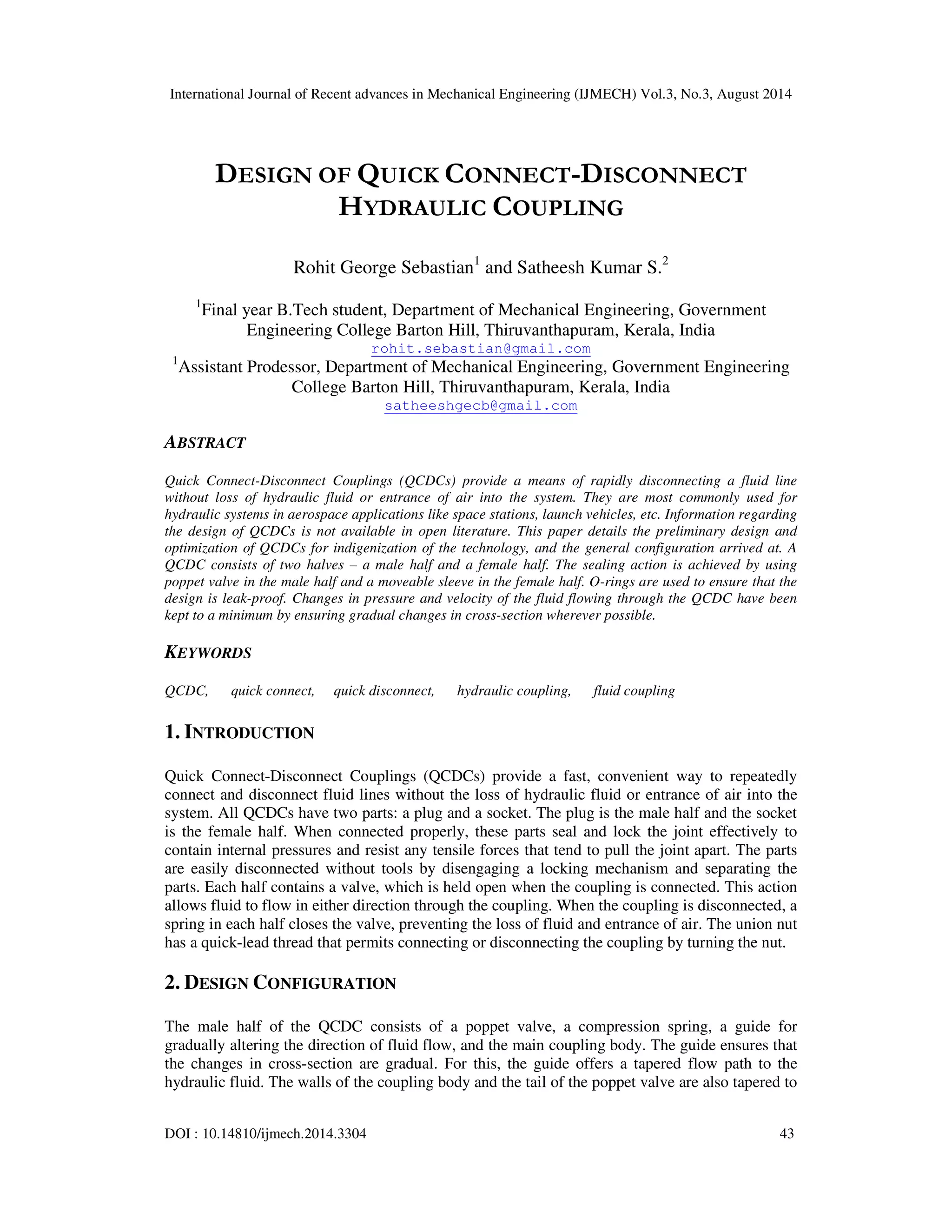
For this, the flow cavity offers a tapered flow path to the hydraulic fluid. The sleeve lies between
the flow cavity and the coupling body. The compression spring is held between the inner surface
of the coupling body and the back face of the sleeve. The sleeve remains suspended in the
hydraulic fluid. An O-ring is provided in the coupling body above the narrow end of the sleeve to
prevent leakage of the QCDC. To facilitate easy machining of the gland for the O-ring, the
coupling body is made as 2 parts and threaded together. A triple start thread, matching the one on
the male half is provided on the coupling body to facilitate mating of the male and female halves
of the QCDC.
45
Figure 3. Half-sectional view of female half in uncoupled position
In the closed or uncoupled position, the poppet valve in the male half pushes against a valve seat
preventing leakage of hydraulic fluid and any entry of air into the system. The compression
spring keeps the poppet valve firmly seated against the valve seat in the uncoupled or closed
position. In the female half of the QCDC, a sleeve is responsible for sealing action in the closed
or uncoupled condition. The compression spring pushes the sleeve against a valve seat.
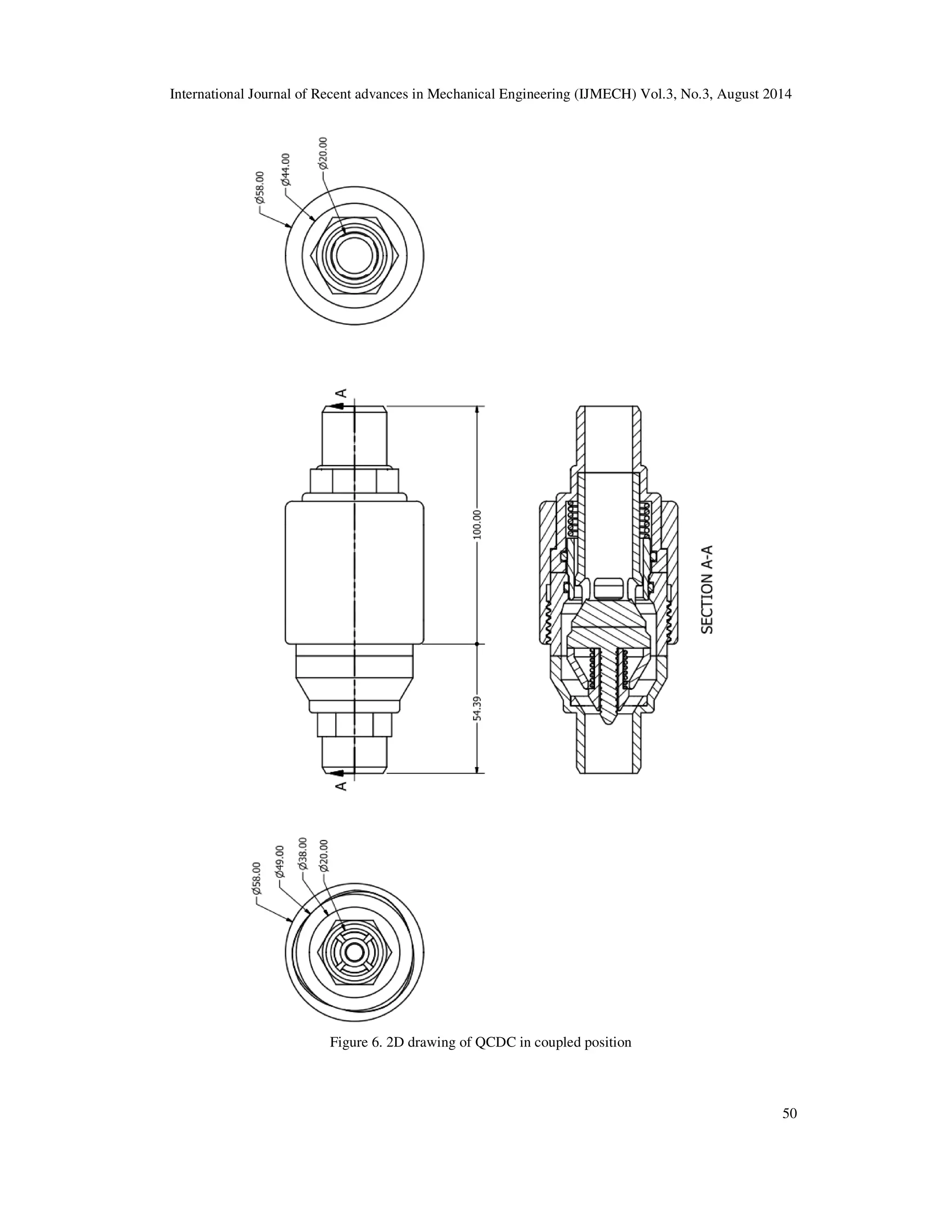
In the coupled position, the flat face of the female half pushes against the head of the poppet
valve, pushing it backwards. At the same time, the valve seat in the male half pushes the sleeve in
the female half backwards, opening a path for the hydraulic fluid to flow. The fluid flows over the
circular face of the female half and the poppet valve in the male half in an annular flow path
formed by the mating of the two coupling halves.
3. DESIGN PARAMETERS
1. Operating Static Pressure – 20.7MPa
2. Burst Pressure – 82.8MPa
3. Rated Flow – 23L/min
4. Inlet Flow Velocity – 1.5m/s
5. Specific Gravity of Fluid – 0.85
6. Kinematic Viscosity of Fluid – 14.2cSt
4. MATERIAL SELECTION
The coupling should be made of a material with high yield stress (to minimize weight) and with
high corrosion resistance to prevent corrosion due to the fluid flowing inside. 15-5 PH stainless
steel (with yield stress of 958MPa[1] Rockwell C hardness 40[2]) has been chosen to make the
coupling body, which includes the stoppers and guides for the poppet valve. 15-5 PH steel has
high strength and hardness along with excellent corrosion resistance, making it ideally suited for
this application. The valve seat should be able to withstand shearing forces due to the force](https://image.slidesharecdn.com/designofquickconnect-disconnecthydrauliccoupling-140918232733-phpapp01/75/Design-of-quick-connect-disconnect-hydraulic-coupling-3-2048.jpg)
![International Journal of Recent advances in Mechanical Engineering (IJMECH) Vol.3, No.3, August 2014
imparted by the poppet valve when it is seated (these forces are due to fluid pressure acting on the
back of the poppet head and due to the force from the spring), despite having a small area of
contact with the inner wall of the coupling. Hence, 15-5 PH steel is suitable for the valve seats as
well.
For proper seating of the poppet valve, the valve seat must be softer than the valve, so that it can
deform slightly (a slight deformation of the valve seat is required for the proper seating of the
valve). Also the same time, the sleeve should bear the pressure of the hydraulic fluid in the
uncoupled position. For this, a material with hardness greater than that of 15-5PH stainless steel
while still having high yield strength is needed. AISI 440C Martensitic stainless steel hardened by
quenching in oil at 1030oC and tempered at 150oC (with yield stress of 1930MPa and Rockwell
C hardness 60[3]) has been chosen for the poppet valve and the sleeve.
The most suitable material for springs are those which can store up the maximum amount of work
or energy in a given weight or volume of spring material, without permanent deformation. These
steels should have a high elastic limit as well as high deflection value. Spring steel should also
possess maximum strength against fatigue effects and shocks. For the compression spring, we
have chosen music wire.[4]
The compound for the O-ring is selected considering several factors such as fluid compatibility,
the effect of various operating environments and conditions, etc. We are designing a QCDC for
use with a petroleum-based hydraulic fluid. Considering compatibility with the hydraulic fluid
and the required operating conditions, Acrylonitrile-Butadiene (NBR) is the best suited
compound for the O-ring.[5]
46
Table 1. Parts and the materials chosen
Sl. No. Part Material Chosen
1 Male Coupling Body 1 15-5 PH stainless steel
2 Male Coupling Body 2 15-5 PH stainless steel
3 Female Coupling Body 1 15-5 PH stainless steel
4 Female Coupling Body 2 15-5 PH stainless steel
5 Female Flow Cavity 15-5 PH stainless steel
6 Male Guide 15-5 PH stainless steel
7 Sleeve AISI 440C Martensitic stainless
steel
8 Poppet Valve AISI 440C Martensitic stainless
steel
9 Spring Cover AISI 440C Martensitic stainless
steel
10 Compression spring for male
half
Music wire
11 Compression spring for female
half
Music wire
12 O-ring for male half Acrylonitrile-Butadiene
13 O-ring for female half Acrylonitrile-Butadiene](https://image.slidesharecdn.com/designofquickconnect-disconnecthydrauliccoupling-140918232733-phpapp01/75/Design-of-quick-connect-disconnect-hydraulic-coupling-4-2048.jpg)
![International Journal of Recent advances in Mechanical Engineering (IJMECH) Vol.3, No.3, August 2014
47
5. DESIGN OF INDIVIDUAL COMPONENTS
The body of the QCDC can be considered as a pressure vessel. For ease of machining and
assembly, both male and female halves of the coupling have been designed as two separate parts.
The two parts of the male half are welded together along the circumference of the meeting edges,
by butt welding using either TIG welding or electron beam welding. The two parts of the female
coupling are threaded together, and for this, threads are cut on the parts as shown in the figure.
The thickness of the body for different diameters were found based on strength using Lame’s
equation [6], with a factor of safety of 2 and a proof pressure of 82.8MPa.
According to Lame’s equation,
.
where, t is the thickness, ri is the internal radius, p is the internal pressure and is the design
value of shear stress.
The thicknesses of some internal cylindrical components such as the flow cavity of the female
half and the sleeve were also found in this way with the same factor of safety, but with a proof
pressure of 20.7MPa for the sleeve. The thickness obtained is rounded off to a convenient value,
and in some cases, increased to account for additional factors such as cutting of threads, to
account for the reduced strength at welded joints, etc.
Since the parts joined by threads are of the same material, shear stress occurs at the pitch line.
The threads designed have a very high margin of safety. The springs have also been designed to
withstand the shear stress caused due to the curvature of the wire and axial loading, with a factor
of safety of 1.5.
6. ASSEMBLY
The coupling body of the male half of the QCDC is made as 2 pieces. The male guide is threaded
to the piece of the male coupling body which has the fluid outlet. The compression spring for the
poppet valve is inserted over the cylindrical portion of the male guide, and the poppet valve is
inserted such that the cylindrical portion of the male guide covers the stem of the poppet valve
and its head rests on the compression spring. The O-ring is inserted into the other piece of the
male half coupling body in the groove provided. The poppet valve should be held back before the
two pieces of the male half coupling are butt welded together by either TIG welding or electron
beam welding.
The coupling body of the female half is also made as 2 pieces. The compression spring for the
sleeve is inserted into the piece having the hydraulic fluid inlet in the cavity provided for the
sleeve and the compression spring. The sleeve is also inserted into the same cavity so that the
broader flat face rests on the compression spring. The sleeve should be held back before the
female flow cavity is threaded into place. The two pieces of the coupling body of the female half
are now threaded together.
Since the above mentioned threaded connections (in both the male and female halves) are
permanent, they are backed up by industrial grade adhesives in the thread cavity.](https://image.slidesharecdn.com/designofquickconnect-disconnecthydrauliccoupling-140918232733-phpapp01/75/Design-of-quick-connect-disconnect-hydraulic-coupling-5-2048.jpg)
![International Journal of Recent advances in Mechanical Engineering (IJMECH) Vol.3, No.3, August 2014
54
REFERENCES
[1] AISI Type S15500 (15Cr-5Ni) Precipitation Hardening Stainless Steel tested at 205°C (400°F),
condition H1025. Available:
http://asm.matweb.com/search/SpecificMaterial.asp?bassnum=MQM15AM
[2] Stainless Steel – Precipitation Hardening – 15/5 PH. Available:
http://www.aalco.co.uk/datasheets/Stainless-Steel_15~5-PH_310.ashx
[3] 440C Martensitic Stainless Steel Bar. Available: http://www.interlloy.com.au/our-products/stainless-steel/
440c-martensitic-stainless-steel-bar/
[4] Materials – Music Wire. Available: http://www.springsandthings.com/music-wire.html
[5] Parker O-ring Handbook. Available: http://www.parker.com/literature/ORD%205700%20Parker_O-Ring_
Handbook.pdf
[6] John F. Harvey (1985) Theory and Design of Pressure Vessels, Van Nostrand Reinhold Company
Authors
Rohit George Sebastian is a final year B.Tech student (Mechanical Engineering) studying at
Government Engineering College, Barton Hill, Thiruvananthapuram.
Satheesh Kumar S, studied B.Tech (Mechanical Engineering) in College of
Engineering, Thiruvananthapuram and M.Tech (Machine Design) in IIT Madras. Joined
Kerala Government Service as Assistant Engineer in 2000 and is currently working as
Assistant Professor in the Department of Mechanical Engineering, Government
Engineering College, Barton Hill, Thiruvananthapuram, Kerala.](https://image.slidesharecdn.com/designofquickconnect-disconnecthydrauliccoupling-140918232733-phpapp01/75/Design-of-quick-connect-disconnect-hydraulic-coupling-12-2048.jpg)

The document presents the design and optimization of quick connect-disconnect couplings (QCDCs), specifically for hydraulic systems in aerospace applications. It details the components, material selection, assembly, and flow characteristics of the QCDC, highlighting its leak-proof design and efficient hydraulic fluid management. The findings indicate that the optimized design maintains laminar fluid flow with minimal pressure drop, making it suitable for various applications, including space stations and hydraulic test stands.


