1. VARs are not Imaginary
1. The following points outline what “imaginary power” is, how it impacts the grid and some
equations to aid understanding.
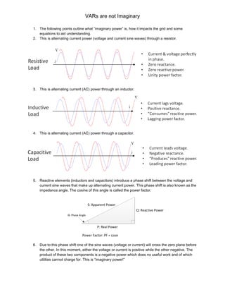
2. This is alternating current power (voltage and current sine waves) through a resistor.
3. This is alternating current (AC) power through an inductor.
4. This is alternating current (AC) power through a capacitor.
5. Reactive elements (inductors and capacitors) introduce a phase shift between the voltage and
current sine waves that make up alternating current power. This phase shift is also known as the
impedance angle. The cosine of this angle is called the power factor.
Q: Reactive Power
P: Real Power
S: Apparent Power
ϴ: Phase Angle
Power Factor: PF = cosϴ
6. Due to this phase shift one of the sine waves (voltage or current) will cross the zero plane before
the other. In this moment, either the voltage or current is positive while the other negative. The
product of these two components is a negative power which does no useful work and of which
utilities cannot charge for. This is “imaginary power!”
2. VARs are not Imaginary
7. In a physical sense, “imaginary” power can also be thought of as the additional power required
overcoming frictional resistance in pushing a block across a rough surface.
8. Transmission lines, large motors and the majority of components on the electrical grid are
inductive by nature and introduce complex impedance to the network.
𝑍 = 𝑅 + 𝑗𝑋𝐿 + 𝑗𝑋𝑐 = 𝑅 𝐿 + 𝑗𝜔𝐿 + −𝑗
1
𝜔𝐶
9. The power consumed by inductors also has both real (MW) and reactive (MVARs) components.
𝑆 = 𝑃𝐿 + 𝑗𝑄 𝐿 = (𝑅 𝐿 + 𝜔𝐿 + −𝑗
1
𝜔𝐶
) 𝑖2
10. Any non-unity (not equal to 1) power factor in the lagging direction (inductive) requires that more
current be supplied by the generator to support reactive loads than would be needed to support
purely resistive loads. This increased current contributes to transmission losses. In this way
inductive loads introduce an additional transmission cost on the grid (i.e. reactive power).
11. As transmission lines grow longer, their reactance (imaginary part of resistance) increases,
current and voltage move further out of phase (lagging direction) and additional VARs must be
generated to support connected loads.
12. Generators are rated in KVA such that their capability to support both real and reactive loads is
apparent. Additional MWs are generated by increasing torque on the generator rotor (i.e.
increased fuel flow). Additional MVARs are generated by increasing field excitation voltage.
13. Generator capability curves define power factor and MW operating limits of the unit. A generator
heavily, inductively loaded will operate at a lower power factor necessitating increased excitation
field current. Again, this increased field current introduces losses and approaches field winding
temperature limits. In this operating mode, series capacitors may be introduced on transmission
lines to make the loads less inductive from the generator’s perspective.
14. Remember, impedance is made up of both resistive and reactive elements. The reactive
elements are as follows:
𝑍𝑡𝑜𝑡 = 𝑅𝑡𝑜𝑡 + 𝑗𝑋𝐿 + 𝑗𝑋 𝐶 𝑋 𝐿 = 𝑗𝜔𝐿 𝑋 𝐶 = −𝑗
1
𝜔𝐶
15. From the above, if the load supplied by a generator is overly inductive (as happens over very long
transmission lines) a capacitor bank can be added to decrease the cumulative reactance (XL+XC).
In doing this, the VARs consumed by the connected loads can be decreased and the generator
can operate more efficiently (more MWs, less MVARs).