
Recommended
More Related Content
Similar to Describe the operating principle of the following FET sensor, and pr.pdf
Similar to Describe the operating principle of the following FET sensor, and pr.pdf (20)
More from akukukkusarees
More from akukukkusarees (20)
Recently uploaded
Recently uploaded (20)
Describe the operating principle of the following FET sensor, and pr.pdf
- 1. Describe the operating principle of the following FET sensor, and provide a detailed diagram (drawing), to illustrate how the sensor functions. Be sure to indicate the type of doping at the source, drain and gate. A field effect transistor (FET) for measuring glucose concentration. Hint: Consider using the glucose oxidase enzyme and measure one of the by-products. As with (a), include a cross-section drawing with proper labeling of doping at the source, drain, and gate, and any molecular interactions at the gate. Solution Introduction For several decades, much attention has been paid to silicon-based biosensors in the field of bioanalytical applications due to their favorable characteristics, which include sensitivity, speed,miniaturization, and low cost. This interest is evident in the numerous studies that have monitored biological events such as nucleic acid hybridizations, protein-protein interactions, antigen-antibody binding, and enzyme-substrate reactions using these silicon-based biosensors. Among these, the ion-sensitive field-effect transistor (ISFET), is one of the most popular electrical biosensors, and has been introduced as the first miniaturized silicon-based chemical sensor. The ISFET, conventionally referred to as a pH sensor, has been used to measure ions concentrations (H+ or OH) in a solution, causing an interface potential on the gate insulator. The ISFET is a type of potentiometric device that operates in a way similar to the way the MOSFET (Metal Oxide Semiconductor Field-Effect Transistor) works. Therefore, in order to evaluate the performance of the ISFET, it makes sense to first understand the general principles behind the operation of the potentiometric sensor. After the introduction of the ISFET biosensor by Bergveld in 1970, and the first report by Caras and Janata regarding the use of an enzymatically modified ISFET for the direct detection of penicillin, numerous biosensors were established on the basis of theoretical development of ISFET technology. For example, there have recently been outstanding advances in the field of ISFET biosensors for use in biosensing research, including the progress of the enzyme-immobilized FET which detects H+ion concentration, the DNA (deoxyribonucleic acid)-modified FET based on DNA hybridization detection, and the cell-based FET for cell metabolism sensing or the measurement of extracellular potential. Currently, the use of ISFET technology encompasses a wide range of applications in a variety of areas,and those in the biomedical and environmental monitoring areas are particularly
- 2. noteworthy. Operating Principle of FET-Based Biosensors In general, a field-effect transistor (FET) consists of three terminals; the source, drain, and gate. The voltage between the source and drain of the FET regulates the current flow in the gate voltage.Specifically, the current-control mechanism is based on an electric field generated by the voltageapplied to the gate. The current is also conducted by only one type of carrier (electrons or holes) depending on the type of FET (n-channel or p-channel). A positive voltage applied to the gate causes positive charges (free holes) to be repelled from the region of the substrate under the gate. These positive charges are pushed downward into the substrate, leaving behind a carrier- depletion region. The depletion region is populated by the bound negative charge associated with the acceptor atoms.These charges are “uncovered” because the neutralizing holes have been pushed downward into the substrate. The positive gate voltage also pulls negative charges (electrons) from the substrate regions into the channel region. When sufficient electrons are induced under the gate, an induced thin n-channel is in effect created, electrically bridging the source and drain regions. The channel is formed by inverting the substrate surface from p-type to n-type (inversion layer). When a voltage is applied between the drain and source with the created channel, a current flows through this n-channel via the mobile electrons (n-type FET). In the case of a p-type semiconductor, applying a positive gate voltage depletes carriers and reduces the conductance, whereas applying a negative gate voltage leads to an accumulation of carriers and an increase in conductance (the opposite effect occurs in n-type semiconductors). The applied gate voltage generates an electric field which develops in the vertical direction. This field controls the amount of charge in the channel, and thus it determines the conductivity of the channel. The gate voltage applied to accumulate a sufficient number of electrons in the channel for a conducting channel is called the threshold voltage (VTH). Note that VTH for an nchannel (p-channel) FET is positive (negative). With these properties, the FET can be configured as a biosensor by modifying the gate terminal with molecular receptors or ion-selective membranes for the analyte of interest. The binding of a charged biomolecule results in depletion or accumulation of carriers caused by change of electric charges on the gate terminal. The dependence of the channel conductance on gate voltage makes FETs good candidates for electrical biosensors because the electric field generating from the binding of a charged biomolecule to the gate is analogous to applying a voltage to a gate. In general, the drain current of the FET-type biosensor is defined as follows
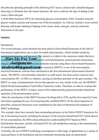
- 3. Structure of ISFET. It consists of source, drain, gate insulator, and reference electrode. Generally, there are two types of planar FET-based biosensors, according to their structure; insulated-gate field-effect transistors (IGFET) and ISFET. In the case of IGFET, particularly MOSFET (metal-oxide-semiconductor field-effect transistor), the gate terminal is electrically isolated from the source and drain terminals. ISFET is similar to IGFET, but in the ISFET, the metal gate is replaced by an ion-selective membrane, electrolyte and a reference electrode. In the case of an ISFET biosensor, the amount of the current flow will be not only determined by the charges of biomolecules interacting on the gate dielectric, but also sensitive to pH, different ions, products of enzyme reactions, etc. An attractive feature of such FETs is that it is possible to detect biomolecular interactions in a label-free manner through a direct change in conductance or a related electrical property BIOSENSOR BASICS The field of biosensor technology originally developed in the 1960’s from electrochemical sensors to detect glucose and urea. These sensors immobilized enzymes (namely urease and glucose oxidase) onto an electrode and measured the concentration of the analyte by the current produced through enzymatic reaction. A biosensor is defined by The National Research Council (part of the U.S. National Academy of Sciences) as a detection device that incorporates a) a living organism or product derived from living systems (e.g., an enzyme or an antibody), b) a transducer to provide an indication, signal, or other form of recognition of the presence of a specific substance in the environment, and c) an output for statistical processing of the data generated. Ideally, biosensors must be designed to detect molecules of analytical significance, pathogens, and toxic compounds to provide rapid, accurate, and reliable information about the analyte of interrogation. A generalized schematic of a biosensor is in Figure, highlighting the flow of how a biosensor works. LABEL-FREE ELECTROCHEMICAL METHODS In this section we will discuss the main types of electrochemical sensors, with emphasis on amperometric and potentiometric based sensors. In particular, we will discuss the operating principles of the amperometric sensor using the most widely accepted device (the glucose sensor), as an example. For potentiometric sensors, we will focus mainly on the ones based upon field-effect transistor (FET) technology, discussing ion selective field effect transistors (ISFET’s) and the more recent nanoscale FET’s. THE GLUCOSE SENSOR: AN AMPEROMETRIC EXAMPLE The glucose enzyme electrode is probably the most studied biosensor method to date, with its roots buried in the original patents by Clark and Lyons in 1962. Moreover, it is the ideal example
- 4. for a point-of-care device already in high demand. An excellent review of the history of electrochemical glucose sensor was done by Joseph Wang in 2008, and goes into depth about all the generations of glucose sensor up to the latest technologies. The basic mechanism of the glucose sensor uses the enzyme glucose oxidase (GOx) and its reaction products to generate a measurable current. the immobilized GOx catalyzes the oxidation of -D-glucose by molecular oxygen producing gluconic acid and hydrogen peroxide. In order to perform this, GOx need a redox catalyst–flavin adenine dinucleotide (FAD) to work as an electron acceptor, which then gets reduced to FADH2 by the reaction below: The first generation of glucose sensors was built upon this principle, but later it was realized oxygen depletion was causing large drifts in the sensors responses which was hard to correct for and interference with competing oxidizers such as ascorbic acid. The interference was in part due to the large anodic potentials (+0.6V vs. Ag/AgCl electrode) that had to be applied in order to oxidize the hydrogen peroxide. Thus, the second generation glucose sensors started using artificial electron carriers to substitute for oxygen in shuttling electron from the enzyme redox center to the electrode, as well as using the enzyme glucose dehydrogenase (GDH), which removes the need for oxygen in the reaction.First, oxygen was replaced with an electron acceptor called a redox mediator. The mediator was reduced instead of oxygen being converted to hydrogen peroxide, which then was reoxidized at the platinum electrode to regenerate the mediator. An example of this is in Figure, whereby most glucose sensors operate on these principles today. Several types of redox mediators are in play, with most of them derivatives of ferrocene, ferricyanide, or quinines, with ferrocene derivatives being the most popular for current devices.However, the Abbott Freestyle devices use an osmium based mediator, which has been the stable for all three generations of the technology.GDH belongs to the class of quinoproteins, which use pyrroloquinoline quinone (PQQ) as cofactor to convert glucose to gluconolactone. GDH is also a dimeric enzyme composed of two identical protein monomers with each monomer binding a PQQ molecule and three calcium ions. These calcium ions activate the PQQ cofactor, and the reaction mechanism is similar to GOx with FAD, except PQQ is the cofactor and does not require oxygen in the reduction. An excellent review by Vashist et. al.highlights the latest type of electrochemical glucose sensors in thorough detail. A table of the current technologies is in Table 2.1 below, along with the largest manufacturers of glucose point-of-care sensors. The main one which I will discuss as an example electrochemical platform is the Abbott Freestyle, which relies on an osmium redox mediator and GDH-PQQ enzyme complex.
- 5. Each blood glucose meter (BGM) test strip has aimed to have high reproducibility, high accuracy, low-cost, rapid results, and low sample volume amounts. These values for the most widely used BGM’s are in Table 2.1 as well. The three main components of the BGM strip are the working, counter, and reference electrodes. Additionally, fill electrodes are put on the device to make sure a proper amount of sample has filled the chamber. A small capillary chamber is located on the electrode substrate to work as reaction container and draw the blood into the device through capillary action. A mixture of enzymes, mediators and other chemical components is coated within the capillary chamber in dry form. This setup is discussed in Figure , and is part of the Abbott Freestyle system. A working electrode, where the enzymes and mediators are dried, is typically composed of carbon ink or vapor deposited gold or palladium, and auxiliary and reference electrode are usually combined and made of the same material. The auxiliary and reference electrode are usually composed of Ag/AgCl and are assembled facing the working electrode at a distance of 50 microns in modern devices. Previously, a large potential of 400-500mV must be applied to the working electrode vs. Ag/AgCl in coplanar electrode devices, but this would cause “redox shuttling” from the mediator back and forth, causing high background noise. However, using osmium mediators, its oxidation potential is negative with respect to other interfering agents, making the other reactions impossible. Moreover, it decrease the diffusion time to the working electrode, and can give readouts within 5 seconds. Most electrochemical devices for various analytes work off the principles of the glucose sensor, but with different enzymes, electrodes, or redox mediators, to generate their signal. FIELD EFFECT TRANSISTOR BASED SENSORS In this section I will discuss the most relevant literature and background into the operating theory of FET’s and how they have been applied to biosensors. FET based devices operate on the principle that changes in the electric field across a dielectric (the gate) cause changes in the source-drain current of the underlying device. Since most biomolecules are charged, their binding to the gate causes a change in the electric field due to their charge density, making FET devices particularly enticing as a biosensor. A few of the benefits of using FET technology as a biosensor include: · High sensitivity due to the current gains inherent in FET devices based on small surface potential changes · Low cost due to the mass scaling and integration of FET devices in most electronics · Label-free since it is able to use the intrinsic charge of a molecule as it
- 6. detection principle Each FET device is based upon a two-terminal device called a metal-oxidesemiconductor capacitor, or MOSCAP. This structure typically contains a top metal gate, an insulating oxide as the dielectric, and a p-type silicon body. A MOS structure, when a bias is applied to the gate, can operate in three regimes, i) accumulation, ii) depletion, and iii) inversion. The three regimes are outline in Figure . When a negative bias is applied to the gate, holes (the majority carrier) from the p-type substrate collect at the silicon/oxide interface and the device is said to be in accumulation. Depletion starts to occur when positive voltages are applied to the gate and holes are repelled from the interface into the silicon, with the voltage between accumulation and depletion modes called the flatband voltage (VFB). When negative charges (the minority) carrier start to collect at the interface the device is said to be at inversion, and the voltage where this occurs is called the threshold voltage. The equations which dictate the threshold voltage (VT) are: Ideally the flatband voltage should only rely on , but all devices contain some amount of the charge densities above. As will be discussed, it has been the goal to minimize these charges as much as possible in the CMOS industry, as they lead to non-ideal device characteristics and degradation of device integrity. Fixed charge is important because it can cause large shifts in threshold voltage, increasing the voltages needed to turn the device on. For transistors exposed to fluids, it is especially important to keep this as low as possible because applying higher voltages leads to higher possibilities of dielectric breakdown and gate leakage. Interface oxide trapped charge can lead to degradation of device turn-on, and mobile charge to device hysteresis when the voltage is swept. Similarly, with fluid based devices these charges can lead to device drift and instability. The most efficient way to study the effect of these defects is using a MOSCAP and looking at the capacitance of the device vs. the gate voltage, most commonly referred to as C-V analysis. Using high frequency C-V’s of a MOSCAP, the effect of these charges on the curve are overly apparent. Interface traps will draw the curve out, leading to poorer sensitivity to applied voltages, while fixed charges will shift the curve left or right from ideal, depending on the charge. A demonstration of how these charges affect C-V characteristics is in Figure A MOSFET is essentially a MOSCAP, but with a 3rd terminal added, known as the source and drain, which forms a conducting channel underneath the MOSCAP. When the surface potential of the oxide (s) reaches a critical value (threshold voltage), the underlying channel will conduct and this is dependent on the gate voltage. The equation for the drain current of a MOSFET is
- 7. well known: Ion Selective Field Effect Transistors, or ISFET’s, are a particular type of FET where the top metal has been removed, and has been replaced by an electrolyte and an electrode, as shown in Figure. The ISFET was originally developed by Bergveld in 1970 , and since then over 600 papers have been published in regards to the ISFET. The main difference between the MOSFET and ISFET is the removal of the metal and replacing it with an electrolyte and an electrode. By doing this, we expose the gate insulator to the solution, and remove the workfunction of the metal, replacing it with a reference electrode potential. The new equation for the threshold voltage of an ISFET is: The pH and ion selective nature of the dielectric layer allows for to change due to the interaction of the ions with the surface, this in turn changing the threshold voltage of the device and providing the devices sensing mechanism. The pH and ion sensitivity of ISFET’s can be described using a site-binding model specific to the electrolyte/insulator interface. An in-depth description for ISFET’s using this model was done by Van Hal et. [109]. In this model, the oxide surface sites are said to be amphoteric, meaning the surface hydroxyl groups can be neutral, protonated, or deprotonated depending on the pH of the bulk solution. Moreover, Van Hal and Eijkel showed how the equation could be related to the equation for capacitors, Q=CV. Essentially, Q is the surface charge in the form of protonated (OH2+) or deprotonated (O-) OH groups of the oxide surface, C is the double-layer capacitance at the interface and V is the resulting surface potential, denoted as the familiar . The capacity for the surface to take up or release protons, in conjunction with the capacitance of the double layer, with a change in pH can be accounted for in a sensitivity factor , , and its influence on the surface potential is given by the following equation: where BS symbolizes the surface buffer capacity, or the ability of the oxide surface to deliver or take up protons, and CS is the differential double-layer capacitance, of which the value is mainly determined by the ion concentration and the Debye length due to that concentration. It can be seen that as approaches 1, near Nernstian sensitivity of the device can be achieved.