
Recommended
More Related Content
Similar to iconichearsttower.pdf
Similar to iconichearsttower.pdf (20)
Recently uploaded
Recently uploaded (20)
iconichearsttower.pdf
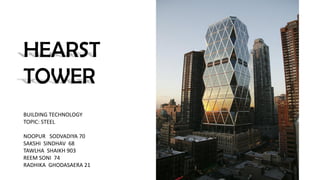
- 1. HEARST TOWER BUILDING TECHNOLOGY TOPIC: STEEL NOOPUR SODVADIYA 70 SAKSHI SINDHAV 68 TAWLHA SHAIKH 903 REEM SONI 74 RADHIKA GHODASAERA 21
- 2. ARCHITECT Norman Foster STRUCTURAL ENGINEER WSP Cantor Seinuk CONSTRUCTION Turner Construction FABRICATORS Cives Steel Fabrication and Mountain Enterprises Foster + Partners is a British international studio for architecture and integrated design. PROJECT TEAM NORMAN FOSTER
- 3. The Hearst Tower is located between 300 West 57th Street and 959 Eighth Avenue, near Columbus Circle, in Midtown Manhattan, New York City. The new addition is made up of 856,000 ft2 Tower is 600 ft tall and incorporates two underground levels. The Hearst Tower became the first LEED Gold Skyscraper in New York City. LOCATION :
- 4. The original six-story structure was built in 1928 and was meant to be the base of a skyscraper expansion. The Great Depression and then World War II postponed these expansion plans. In 2001, the Hearst Corporation decided to consolidate the offices it rents for nearly 2,000 employees in a new 46-story tower. BACKGROUND
- 5. HISTORIC 1926 LANDMARK FAÇADE The glass and steel addition sits atop a sixstory cast stone base, which was designed by Joseph Urban in 1928. EXISTING BUILDING COST $2 million Only the facade of the existing building was saved and one bay of the original steel frame was kept in order to keep the limestone stable. TOWER ADDITION COST $500 million
- 6. DESIGN CONCEPT Preserving New York’s Heritage-- The Landmark Facade An important design specification was the preservation of the existing landmark facade and its incorporation into the new tower design. Hearst’s original intention for this building was to provide a high quality work environment for his employees The building truly celebrates the marriage of the old and new
- 7. The original building an approximate footprint of 200 ft by 200 ft The tower has two distinct zones 1 the zone below 10th floor contains entrance at street level and lobby, cafeteria 2 auditorium at the 3rd floor with an approximately 80 ft high interior open space The tower is connected to the existing landmark facade at the 7th level by the horizontal skylight system spanning approximately 40 ft BUILDING LAYOUT
- 8. Three sides of the building face streets and views The west side is against another building; so the core was shifted toward the western edge The office zone starts at 110ft above street level from the 10th floor to the top of the building Composite steel and concrete floors with 40 ft interior column free spans were utilized for open office planning
- 9. SOIL sharp drops in elevation of bedrock varied up to 30 feet SPREAD FOOTING used on half the building on top of rock CAISSONS used on the other half and embedded into rock FOUNDATION
- 10. 12 30-ton, 44-inch-square box mega columns assembled from 4-inch rolled steel plates 90-foot “mega-diagonals” Grade 50 steel members were used throughout, with 65 ksi elements A system of 40-ton beams at the tenth floor, integrated with skylights, forms a diaphragm that braces the structure laterally and ties the old building to the new. a shimmering pewter-like linen finish, 5- millimeter stainless steel cladding wraps the exterior structural system, adding that same subtle shimmer to the streetscape and skyline. FIRST TO TENTH FLOOR STRUCTURE
- 14. In the diagrid-framed system, the gravity and lateral loads are distributed through the sloped column and spandrel beam members as axial tension or compression The system allows broad interior spans of more than 40 feet between columns.
- 16. Prefabricated node The nodes are basically symmetrical as well as repetitious An innovative two-point crane pick Combination of standard and oversized holes to help with site erection Complex nodes bolted into six different 12-inch, H-column-type diagrid elements three basic types of nodes “bird’s mouths” in order to avoid large cantilevered floor plates between the corner nodes CONNECTION IN STRUCTURE
- 18. LOAD TRACING GRAVITY The gravity and vertical load from the building will distribute toward the apex of the diagonal structure. The forces will be divided into the other diagonal members and transfer into the bottom section. The diagrid creates a highly efficient tube structure by being composed of a network of triangulated trusses which interconnect all four faces of the tower. The diagrid system is inherently highly redundant by providing a structural network allowing multiple load paths.
- 19. Considerations would affect the design of diagrid system and selection of module: ● geometry of the building ● occurrence of eccentric loading ● structural efficiency ● floor-to-floor height ● requirements for fenestration pattern and window sizes ● selection of AESS or concealed steel structure 75 degree or 105 degree slope with 8 storeys each module is the most efficient selection