7.pdf This presentation captures many uses and the significance of the number...
Workholding devices
1. INTRODUCTION TO WORKHOLDING
Over the past century, manufacturing has made considerable progress. New machine tools, high-
performance cutting tools, and modern manufacturing processes enable today's industries to make parts faster
and better than ever before. Although workholding methods have also advanced considerably, the basic principles
of clamping and locating are still the same.
HISTORY
The first manufactured products were made one at a time. Early artisans started with little more than raw
materials and a rough idea of the finished product. They produced each product piece by piece, making each part
individually and fitting the parts into the finished product. This process took time. Moreover, the quality and
consistency of products varied from one artisan to the next. As they worked, early manufacturing pioneers
realized the need for better methods and developed new ideas.
Eventually, they found the secret of mass production: standardized parts. Standard parts not only speeded
production, they also ensured the interchangeability of parts. The idea may be obvious today, but in its time, it
was revolutionary.
These standard parts were the key to enabling less-skilled workers to replicate the skill of the craftsman on a
repetitive basis. The original method of achieving consistent part configuration was the template. Templates for
layout, sawing, and filing permitted each worker to make parts to a standard design. While early templates were
crude, they at least gave skilled workers a standard form to follow for the part. Building on the template idea,
workers constructed other guides and workholders to make their jobs easier and the results more predictable.
These guides and workholders were the ancestors of today's jigs and fixtures.
Yesterday's workholders had the same two basic functions as today's: securely holding and accurately
locating a workpiece. Early jigs and fixtures may have lacked modern refinements, but they followed many of the
same principles as today’s workholder designs.
DEFINITIONS
Often the terms "jig" and "fixture" are confused or used interchangeably; however, there are clear
distinctions between these two tools. Although many people have their own definitions for a jig or fixture, there is
one universal distinction between the two. Both jigs and fixtures hold, support, and locate the workpiece. A jig,
however, guides the cutting tool. A fixture references the cutting tool. The differentiation between these types of
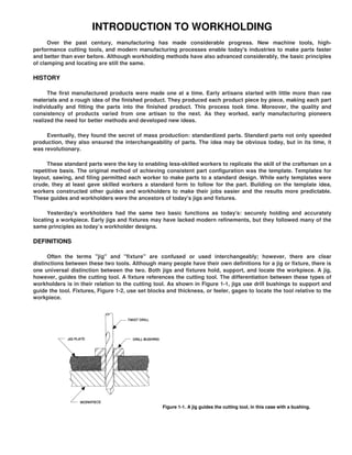
workholders is in their relation to the cutting tool. As shown in Figure 1-1, jigs use drill bushings to support and
guide the tool. Fixtures, Figure 1-2, use set blocks and thickness, or feeler, gages to locate the tool relative to the
workpiece.
Figure 1-1. A jig guides the cutting tool, in this case with a bushing.
2. Figure 1-2. A fixture references the cutting tool, in this case with a set block.
Jigs
The most-common jigs are drill and boring jigs. These tools are fundamentally the same. The difference lies
in the size, type, and placement of the drill bushings. Boring jigs usually have larger bushings. These bushings
may also have internal oil grooves to keep the boring bar lubricated. Often, boring jigs use more than one bushing
to support the boring bar throughout the machining cycle.
In the shop, drill jigs are the most-widely used form of jig. Drill jigs are used for drilling, tapping, reaming,
chamfering, counterboring, countersinking, and similar operations. Occasionally, drill jigs are used to perform
assembly work also. In these situations, the bushings guide pins, dowels, or other assembly elements.
Jigs are further identified by their basic construction. The two common forms of jigs are open and closed.
Open jigs carry out operations on only one, or sometimes two, sides of a workpiece. Closed jigs, on the other
hand, operate on two or more sides. The most-common open jigs are template jigs, plate jigs, table jigs, sandwich
jigs, and angle plate jigs. Typical examples of closed jigs include box jigs, channel jigs, and leaf jigs. Other forms
of jigs rely more on the application of the tool than on their construction for their identity. These include indexing
jigs, trunnion jigs, and multi-station jigs.
Specialized industry applications have led to the development of specialized drill jigs. For example, the need
to drill precisely located rivet holes in aircraft fuselages and wings led to the design of large jigs, with bushings
and liners installed, contoured to the surface of the aircraft. A portable air-feed drill with a bushing attached to its
nose is inserted through the liner in the jig and drilling is accomplished in each location.
Fixtures
Fixtures have a much-wider scope of application than jigs. These workholders are designed for applications
where the cutting tools cannot be guided as easily as a drill. With fixtures, an edge finder, center finder, or gage
blocks position the cutter. Examples of the more-common fixtures include milling fixtures, lathe fixtures, sawing
fixtures, and grinding fixtures. Moreover, a fixture can be used in almost any operation that requires a precise
relationship in the position of a tool to a workpiece.
Fixtures are most often identified by the machine tool where they are used. Examples include mill fixtures or
lathe fixtures. But the function of the fixture can also identify a fixture type. So can the basic construction of the
tool. Thus, although a tool can be called simply a mill fixture, it could also be further defined as a straddle-milling,
plate-type mill fixture. Moreover, a lathe fixture could also be defined as a radius-turning, angle-plate lathe fixture.
The tool designer usually decides the specific identification of these tools.
3. Tool or Tooling
The term "tool" encompasses both jigs and fixtures. Essentially, it is a generic term describing a workholder
which is identified with a part or machine. Sometimes "tool" is used to refer to a cutting tool or a machine tool, so
it is important to make clear distinctions.
Workholders
Another term which describes both jigs and fixtures is "workholder." A broad term, it frequently identifies
any device which holds, supports, and locates a workpiece. In addition to jigs and fixtures, vises, collets, clamps,
and other similar devices are also workholders.
PERMANENT AND TEMPORARY WORKHOLDERS
Jigs and fixtures are most often found where parts are produced in large quantities, or produced to complex
specifications for a moderate quantity. With the same design principles and logic, workholding devices can be
adapted for limited-production applications. The major difference between permanent and temporary workholders
is the cost/benefit relationship between the workholder and the process. Some applications require jigs and
fixtures solely for speed; others require less speed and higher precision. The requirements of the application have
a direct impact on the type of jig or fixture built and, consequently, the cost.
Permanent Jigs and Fixtures
Workholders for high-volume production are usually permanent tools. These permanent jigs and fixtures are
most often intended for a single operation on one particular part. The increased complexity of permanent
workholders yields benefits in improved productivity and reduced operator decision-making, which result in the
tool having a lower average cost per unit or per run. Therefore, more time and money can be justified for these
workholders.
In the case of hydraulic or pneumatic fixtures, inherent design advantages can dramatically improve
productivity and, hence, reduce per-unit costs even further, even though the initial cost to construct these fixtures
is the most expensive of all fixture alternatives. In some cases, where machine-loading considerations are
paramount, such as a pallet-changing machining center, even duplicate permanent fixtures may be justified.
Permanent jigs and fixtures are typically constructed from standard tooling components and custom-made
parts. Figure 1-3 shows a typical permanent workholder for a drilling operation.
Figure 1-3. A permanent workholder used for a drilling operation.
Low-volume runs and ones with fewer critical dimensions are often produced with throwaway jigs and
fixtures. These tools would typically be one-time-use items constructed from basic materials at hand and
discarded after production is complete. Although throwaway jigs and fixtures are technically permanent
workholders, in effect they are actually temporary.
4. General-Purpose Workholders
In many instances, the shape of the part and the machining to be performed allow for the use of a general-
purpose workholder such as a vise, collet, or chuck. These workholders are adaptable to different machines and
many different parts.
Since they are not part-specific, their versatility allows for repeated use on a variety of different or limited-
production runs. The cost of these workholders would usually be averaged over years and might not even be a
factor in job-cost calculations. The general-purpose nature of these workholders necessitates a higher level of
operator care and attention to maintain consistency and accuracy. For these reasons, general-purpose
workholders are not preferred for lengthy production runs.
Modular Fixtures
Modular fixtures achieve many of the advantages of a permanent tool using only a temporary setup. Depicted
in Figure 1-4, these workholders combine ideas and elements of permanent and general-purpose workholding.
Figure 1-4. Modular workholders combine ideas and elements of both permanent and temporary workholding to make inexpensive-yet-
durable workholders.
The primary advantage of modular fixtures is that a tool with the benefits of permanent tooling (setup
reduction, durability, productivity improvements, and reduced operator decision-making) can be built from a set of
standard components. The fixture can be disassembled when the run is complete, to allow the reuse of the
components in a different fixture. At a later time the original can be readily reconstructed from drawings,
instructions, and photographic records. This reuse enables the construction of a complex, high-precision tool
without requiring the corresponding dedication of the fixture components.
Figure 1-5 shows how modular fixturing fits into the hierarchy of workholding options, ranking below
permanent fixturing yet above general-purpose workholders. Virtually every manufacturer has good applications
for each of these three options at one time or another.
5. Figure 1-5. The hierarchy of workholding options.
DESIGN CONSIDERATIONS
The principal considerations when choosing among workholder varieties fall into three general categories:
tooling cost, tooling details, and tooling operation. Although each of these categories is separated here, in
practice they are interdependent. The following are some design differences and considerations for permanent,
general-purpose, and modular workholders.
Tooling Costs
The total cost of any jig or fixture is frequently the major area of consideration in many workholder designs.
Although initial cost is a major element, it should not be the basis for accepting or rejecting any tooling option.
A more-proper economic evaluation of the workholder design takes into consideration many other factors.
As discussed previously, permanent fixtures have distinct advantages in the production of high-volume and high-
precision parts. They also typically reduce machine setup time, machine cycle time, and the level of operator skill
required to produce satisfactory quality output. Over a long production run, or a series of runs in the life of a tool,
the average cost of the tool per piece produced can be quite low.
General-purpose workholders are more expensive than temporary tools in most cases, but their utility and
flexibility often allow these workholders to be regarded as a capital cost to be amortized over a period of time
without regard to actual usage. Similarly, modular fixturing is typically a capital investment to be amortized over a
set lifespan, with an average cost assigned to usage for each anticipated job.
Another cost to be considered is workholder disposition. Permanent fixtures require storage and
maintenance to keep them available for their next use. General-purpose tools are reused extensively, but still incur
some costs for maintenance and storage. Similarly, modular fixtures will be disassembled, and the components
maintained, stored, and reused frequently.
6. Tooling Details
Tooling details are the overall construction characteristics and special features incorporated into the jig or
fixture. Permanent workholders are designed and built to last longer than temporary workholders. So, permanent
jigs and fixtures usually contain more-elaborate parts and features than temporary workholders.
There are several other differences between permanent and temporary workholders in this area. These
include the type and complexity of the individual tooling elements, the extent of secondary machining and
finishing operations on the tool, the tool-design process, and the amount of detail in the workholder drawings.
Since the elements for modular workholders are usually part of a complete set, or system, only rarely will
additional custom components need to be made.
Permanent workholders contain different commercial tooling components based on expected tool usage.
Permanent jigs intended for a high-volume drilling operation, for example, often use a renewable bushing and liner
bushing together. A throwaway jig for a smaller production run often uses a simple press-fit bushing.
The secondary operations normally associated with tooling include hardening, grinding, and similar
operations to finish the workholder. Usually, permanent workholders are hardened and ground to assure their
accuracy over a long production run. Since they are intended only for short production runs, throwaway jigs and
fixtures do not require these operations. Another secondary operation frequently performed on permanent tools,
but not temporary tools, is applying a protective finish, such as black oxide, chrome plating, or enamel paint.
In designing a permanent workholder, the designer often makes detailed engineering drawings to show the
toolroom exactly what must be done to build the workholder. With temporary workholders, the design drawings
are often sent to the toolroom as simple freehand sketches.
Permanent tools are normally designed for long-term use. This being the case, the drawings and engineering
data for the permanent jig or fixture then become a permanent record. With modular workholders, the designer
may either construct drawings or specify building the workholder directly around the part. Here only a parts list
and photographs or video tape are kept as a permanent record.
Certain workholding applications require special fixture characteristics. For example, a particularly corrosive
environment may require stainless steel components and clamps to deliver a satisfactory life cycle. In other
cases, variable workpiece dimensions, as in a casting, necessitate clamping devices which can compensate for
these variations. Appearance of a finished part might require the use of nylon, plastic, or rubber contact points to
protect the part.
Similarly, the selection of tooling details can enhance the productivity of some permanent tools. For
example, utilizing small hydraulic clamps may allow loading many parts on a workholder due to the compactness
of the design. This would enhance productivity by reducing load/unload time as a percentage of total cycle time.
Duplicate fixtures are sometimes justified for machining centers because they allow loading of parts on one pallet
during the machining cycle on the other pallet.
Tooling Operation
The performance of any workholder is critical to the complete usefulness of the tool. If the workholder
cannot perform the functions desired in the manner intended, it is completely useless, regardless of the cost or
the extent of the detail. As the performance of a permanent, modular, or general-purpose workholder is
considered, several factors about the machine tools must be known. These factors include the type, size, and
number of machine tools needed for the intended operations.
Workholders are sometimes designed to serve multiple functions. For example, it is possible to have a
workholder that acts both as a drill jig and a milling fixture. These tools are called combination tools or multiple-
function workholders. Figure 1-6 shows a typical temporary workholder for drilling and milling operations on the
same part. In this example, since the workholder has provisions for both milling and drilling, it is classified as both
a drill jig and milling fixture.
7. Figure 1-6. A combination drill jig/milling fixture used for both types of operations on the same part.
Other machine considerations may come into play as well. On numerically controlled machines, for example,
care must be taken in fixture design to position clamps out of the cutting tool's path. Pallet machines require
different fixtures than other machines. Obviously, vertical mills would be tooled differently than horizontal mills.
Likewise, the way parts are loaded onto the fixture has implications for fixture design.
Despite the workholder design or the size of the production run, every jig or fixture must meet certain criteria
to be useful. These criteria include accuracy, durability, and safety. Accuracy, with regard to jigs and fixtures, is
the ability of a workholder to produce the desired result, within the required limits and specifications, part after
part, throughout the production run.
To perform to this minimum level of accuracy, the workholder must also be durable. So, the jig or fixture
must be designed and built to maintain the required accuracy throughout the expected part production. If part
production is continuous, year after year, the jig or fixture must be more durable than is necessary for only one
production run.
The final consideration, safety, is actually the most important. No matter how good the design or
construction, or how well it produces the desired accuracy, if the workholder is not safe, it is useless. Safety is a
primary concern in the design of any workholder.
Safety, as well as speed and reliability of part loading, can often be improved by the use of power clamping,
either pneumatic or hydraulic. Once set, power clamps will repeatedly clamp with the identical force. This is not
always true with manual clamps, which depend on operator diligence for the proper application of clamping force.
In addition, power-clamping systems can have interlocks to the machine control which will shut the machine down
if the system loses power—a clear safety advantage for both operator and machine tool.
APPLICATIONS FOR JIGS AND FIXTURES
Typically, the jigs and fixtures found in a machine shop are for machining operations. Other operations,
however, such as assembly, inspection, testing, and layout, are also areas where workholding devices are well
suited. Figure 1-7 shows a list of the more-common classifications and applications of jigs and fixtures used for
manufacturing. There are many distinct variations within each general classification, and many workholders are
actually combinations of two or more of the classifications shown.
EXTERNAL-MACHINING APPLICATIONS:
Flat-Surface Machining
• Milling fixtures
• Surface-grinding fixtures
• Planing fixtures
• Shaping fixtures
9. CREATIVE TOOL DESIGN
The first step in designing any jig or fixture is a thorough evaluation of its functional requirements. The goal
is to find a balanced combination of design characteristics at a reasonable cost. The part itself, processing,
tooling, and machine-tool availability may all affect the extent of planning needed. Preliminary analysis may take
from a few hours up to several days for more-complicated designs.
To design a workholder, begin with a logical and systematic plan. With a complete analysis, very few design
problems occur. Workholder problems occur when design requirements are forgotten or underestimated. No
specific formula or method works for every design, but the designer can employ a deliberate and logical system in
the initial planning and design.
Tool design is essentially an exercise in problem solving. Creative problem solving can be described as a
five-step process: 1) Identifying and defining the problem; 2) Gathering and analyzing information; 3)
Brainstorming for alternative solutions; 4) Choosing the best solution; 5) Implementing the solution. This five-step
process adapted to jig-and-fixture designs is shown in Figure 2-1.
Figure 2-1. Five steps that make up a good, systematic tool-design process.
10. DEFINING REQUIREMENTS
The first step in the tool-design process should be to clearly state the problem to be solved, or needs to be
met. These requirements should be stated as broadly as possible, but specifically enough to define the scope of
the design project.
The new tooling might be required either for first-time production of a new product, or to improve production
of an existing part. When improving an existing job, the goal might be greater accuracy, faster cycle times, or
both. Tooling might be designed for one part, or an entire family.
Tool design is an integral part of the product-planning process, interacting with product design,
manufacturing, and marketing. To reach an optimum solution, all four of these groups need to work together
concurrently.
GATHERING AND ANALYZING INFORMATION
In the second design phase, all data is collected and assembled for evaluation. The main sources of
information are the part print, process sheets, and machine specifications. When collecting this information, make
sure that part documents and records are current. For example, verify that the shop print is the current revision,
and the processing information is up to date. Check with the product-design department for pending part
revisions.
An important part of the evaluation process is notetaking. Complete, accurate notes allow the designer to
record important information. All ideas, thoughts, observations, and any other data about the part or tool are then
available for later reference. It is always better to have too many ideas about a particular design than not enough.
Good notes also minimize the chance that good ideas will be lost.
Four categories of design considerations need to be taken into account at this time: the workpiece,
manufacturing operations, equipment, and personnel. A checklist is shown in Figure 2-2.
11. CHECKLIST FOR DESIGN CONSIDERATIONS
Figure 2-2. Considerations when gathering and analyzing information for a tool design
These categories, while separately covered here, are actually interdependent. Each is an integral part of the
evaluation phase and must be thoroughly thought out before beginning the workholder design.
Workpiece Considerations
Workpiece specifications are usually the most-important factors and have the largest influence on the
workholder's final design. Typically these considerations include the size and shape of the part, the accuracy
required, the properties of the part material, locating and clamping surfaces, and the number of pieces.
Operation Considerations
These considerations include the type of operations required for the part, the number of operations
performed, the sequence of operations, inspection requirements, and time restrictions.
Equipment Considerations
Equipment considerations control the type of equipment needed to machine, assemble, and inspect a part.
Often the available equipment determines whether the workholder is designed for single or multiple parts. A
12. process engineer sometimes selects the equipment for required functions before the tool designer begins the
design. Still, the tool designer should verify equipment choices for each operation.
A vertical milling machine, for example, is well suited for some drilling operations. But for operations that
require a drill jig, a drill press is the most-cost-effective machine tool. Typically, equipment criteria include the
following factors: types and sizes of machine tools, inspection equipment, scheduling, cutting tools, and general
plant facilities.
Personnel Considerations
Personnel considerations deal with the end user, or operator, of the equipment. Most special tools are
designed to be used by shop personnel, so the design of any workholder must be made with the operator in mind.
The first and most-important consideration in this phase is safety. No tool should ever be designed without
complete safety in mind.
Additional factors typically considered in this category are operator fatigue, efficiency, economy of motion,
and the speed of the operation. The designer must also know and understand the general aspects of design safety
and all appropriate government and company safety rules and codes.
DEVELOPING SEVERAL OPTIONS
The third phase of the tool-design process requires the most creativity. A typical workpiece can be located
and clamped many different ways. An important strategy for successful tool design is brainstorming for several
good tooling alternatives, not just choosing one path right away.
During this phase, the designer's goal should be adding options, not discarding them. In the interest of
economy, alternative designs should only be developed far enough to make sure they are feasible, and to do a
cost estimate.
Brainstorming for Ideas
The designer usually starts with at least three options: permanent, modular, and general-purpose
workholding, as seen in Figure 2-3. Each of these options has many clamping and locating options of its own. The
more standard locating and clamping devices that a designer is familiar with, the more creative he can be.
Figure 2-3. Most tool-design projects begin with three general options: permanent, modular, and general-purpose workholding. Different
methods of locating and clamping further increase the number of options.
There is seldom only one way to locate a part. Options include flat exterior surfaces (machined and
unmachined), cylindrical and curved exterior surfaces, and internal features (such as holes and slots). The choice
of standard locating devices is quite extensive.
13. Similarly, there are countless ways to clamp a part. For example, a workpiece can be clamped from the top,
by gripping its outside edge, or gripping an internal surface. The choice of standard clamping devices is also very
broad.
Design Sketches
For preliminary sketches of the tool, one good idea is to use several colored pencils. Often, black is used to
sketch the tool, red for the part, and blue for the machine tool. The different colors allow you to see, at a glance,
which areas of the sketch show what part of the assembled unit. Another idea: use graph paper to keep the sketch
proportional. Either plain or isometric graph paper works well for most design sketches.
The exact procedure used to construct the preliminary design sketches is not as important as the items
sketched. For the most part, the preliminary sketch should start with the part to be fixtured. The required locating
and supporting elements should be the next items added, including a base. The next step is to sketch the
clamping devices. Once these elements are added to the sketch, the final items to add are the machine tool and
cutters. Sketching these items together on the preliminary design sketch helps identify any problem areas in the
design of the complete workholder.
CHOOSING THE BEST OPTION
The fourth phase of the tool-design process is a cost/benefit analysis of different tooling options. Some
benefits, such as greater operator comfort and safety, are difficult to express in dollars but are still important.
Other factors, such as tooling durability, are difficult to estimate. Cost analysis is sometimes more of an art than a
science.
Workholder-cost analysis compares one method to another, rather than finding exact costs. So, even though
the values used must be accurate, estimates are acceptable. Sometimes these methods compare both proposed
tools and existing tools, so, where possible, actual production data can be used instead of estimates.
Initial Tooling Cost
The first step of evaluating the cost of any alternative is estimating the initial cost of the workholder. Add the
cost of each element to the labor expense needed to design and build the jig or fixture.
To make this estimate, an accurate sketch of the tool is made first. Each part and component of the tool is
numbered and listed individually. Here it is important to have an orderly method to outline this information. Figure
2-4 shows one way to make this listing. The exact appearance of the form is unimportant; only the information is
important.
14. Figure 2-4. Itemized listing of components for a workholder.
The next step is calculating the cost of material and labor for each tool element. Once again, it is important to
have an orderly system of listing the data. First list the cost of each component, then itemize the operations
needed to mount, machine, or assemble that component. Once these steps are listed, estimate the time required
for each operation for each component, then multiply by the labor rate. This amount should then be added to the
cost of the components and the cost of design to find the estimated cost of the workholder.
For modular fixtures, total component cost should be amortized over the system's typical lifetime. Although
somewhat arbitrary, dividing total component cost by 100 (10 uses per year, for ten years) gives a fair estimate.
Cost Comparison
The total cost to manufacture a part is the sum of per-piece run cost, setup cost, and tooling cost. Expressed
as a formula:
The following example shows three tooling options for the part in Figure 2-3: 1) a modular fixture; 2) a
permanent fixture; 3) a permanent fixture using hydraulic power workholding. Each variable in the cost equation is
explained separately below.
Run Cost. This is the variable cost per piece to produce a part, at shop labor rate (material cost does not
need to be included as long as it is the same for all fixturing options). In our example, run costs for the permanent
and modular fixtures are the same, while power workholding lowers costs by improving cycle time and reducing
scrap.
15. Setup Cost. This is the cost to retrieve a fixture, set it up on the machine, and return it to storage after use.
The permanent fixture is fastest to set up, the power-workholding fixture is slightly slower due to hydraulic
connections, and the modular fixture is slowest due to the assembly required.
Lot Size. This is the average quantity manufactured each time the fixture is set up. In our example, lot size is
the same for all three options.
Initial Tooling Cost. This is the total cost of labor plus material to design and build a fixture (as explained in
the previous section). The modular fixture is least expensive because components can be reused, the permanent
fixture next, and the hydraulic fixture most expensive.
Total Quantity Over Tooling Lifetime. This quantity, the last remaining variable, is the lesser of 1) total
anticipated production quantity and 2) the quantity that can be produced before the tooling wears out. The
following results are obtained by evaluating the cost-per-part formula at different lifetime quantities:
For a one-time run of 100 pieces, the modular fixture is clearly the most economical. If ten runs (1,000 pieces)
are expected, the permanent fixture is best. For 2,500 pieces and above, the power workholding fixture would be
the best choice. This analysis assumes that all noneconomic factors are equal.
16. IMPLEMENTING THE DESIGN
The final phase of the tool-design process consists of turning the chosen design approach into reality. Final
details are decided, final drawings are made, and the tooling is built and tested.
Guidelines for Economical Design
The following guidelines should be considered during the final-design process. These rules are a mix of
practical considerations, sound design practices, and common sense. Application of these rules makes the
workholder less costly, and improves its efficiency and operation.
Use Standard Tooling Components. The economies of standardized parts apply to tooling components as
well as to manufactured products. Standard tooling components, readily available from your industrial supplier,
include clamps, locators, supports, studs, nuts, pins, and a host of other elements. Most designers would never
think of having the shop make cap screws, bolts, or nuts for a workholder. For the same reason, virtually no
standard tooling components should be made in-house. The first rule of economic design is: Never build any
component you can buy. Commercially available tooling components are manufactured in large quantities for
much greater economy.
Labor is usually the largest cost element in the building of any workholder. Standard tooling components are
one way to cut labor costs. Always look for new workholding products to make designs simpler and less
expensive. Browse through catalogs and magazines to find new products and application ideas. In most cases,
the cost of buying a component is less than 20% of the cost of making it.
Use Prefinished Materials. Prefinished and preformed materials should be used where possible to lower
costs and simplify construction. These materials include precision-ground flat stock, drill rod, structural sections,
cast tooling sections, precast tool bodies, tooling plates, and other standard preformed materials. Including these
materials in a design both reduces the design time and lowers the labor cost.
Eliminate Unneeded Finishing Operations. Finishing operations should never be performed for cosmetic
purposes. Making a tool look better can often double the cost of the fixture. Here are a few suggestions to keep in
mind with regard to finishing operations:
• Machine only the areas important to the function and operation of the tool. For example, do not machine
the edges of a baseplate. Just remove the burrs.
• Harden only those areas of the tool subject to wear.
• Grind only the areas of the fixture where necessary for the operation of the tool.
Keep Tolerances As Liberal As Possible. The most-cost-effective tooling tolerance for a locator is
approximately 30 to 50% of the workpiece's tolerance. Tighter tolerances normally add extra cost to the tool with
little benefit to the process. Where necessary, tighter tolerances can be used, but a tighter tolerance does not
necessarily mean a better tool, only a more expensive tool.
Simplify Tooling Operation. Elaborate designs often add little or nothing to the function of the jig or fixture.
Complex mechanical clamping systems, for example, are often elaborate and unneeded designs. More often, a
power clamp could do the same job at a fraction of the cost. Cosmetic details are another example of little gained
for the money spent. These details may make the tool look good, but seldom justify the added cost.
Keep the function and operation of a workholder as simple as possible. The likelihood of breakdowns and
other problems increases with complex designs. These problems multiply when moving parts are added to the
design. Misalignment, inaccuracy, wear, and malfunctions caused by chips and debris can cause many problems
in the best tool designs.
Reducing design complexity also reduces misunderstandings between the designer and the machine
operator. Whenever possible, a workholder's function and operation should be obvious to the operator without
instructions.
17. Manual Drawings
Once sketches and the basic workholder design have been completed, final engineering drawings can be
prepared. Copies of the engineering drawings, also called shop prints, are used by the toolroom to build the
workholder.
Manual drawing is the process of constructing engineering drawings by hand on a drawing board. The
easiest way to reduce drawing time is by simplifying the drawing. Words or symbols should be used in place of
drawn details where practical. All extra or unnecessary views, projections, and details should be eliminated from
the drawing. This cuts the time spent drawing details that add little to the meaning of the drawing.
Drawing a complete clamp assembly, for example, adds very little to the complete design. Simply showing
the nose of the clamp in its proper relation to the workpiece, along with specifying its part number, conveys the
same information in a fraction of the time.
Computer-Aided Design
Computers are rapidly replacing drawing boards as the preferred tool for preparing engineering drawings.
Almost every area of design is affected by the computer. Computers, from large mainframes to microcomputers,
are becoming standard equipment in many design departments.
A standard tooling library, shown in Figure 2-5, is often used to add the fixturing components and elements
to the tool drawing. Using a standard library in designing the workholder dramatically reduces drawing time. All
components are drawn to full scale in a variety of views. Each component can be called up from the library and
placed on the drawing where it is required.
Figure 2-5. Using a standard CAD tooling library can dramatically reduce design time.
A CAD system is also sometimes useful during the initial phase of developing numerous tooling options.
Computer-aided design is sometimes faster than sketching by hand, especially when detailed cost estimates are
required.
Building and Testing the Workholder
Once drawings have been thoroughly checked, the next step is building the actual workholder. During the
building stage, the designer should ensure the toolroom knows exactly what must be done when making the tool.
By periodically checking with the toolmakers, the designer can help eliminate any possible misunderstandings
and speed the building process. If there are any difficulties with the design, the designer and toolmaker, working
together, can solve the problems with a minimum of lost time.
After the tool is completed and inspected, the last step is tool tryout. The workholder is set up on the
machine tool and several parts are run. The designer should be on hand to help solve any problems. When the
tool proves itself in this phase, it is ready for production.
18. LOCATING AND CLAMPING PRINCIPLES
Locating and clamping are the critical functions of any workholder. As such, the fundamental principles of
locating and clamping, as well as the numerous standard components available for these operations, must be
thoroughly understood.
BASIC PRINCIPLES OF LOCATING
To perform properly, workholders must accurately and consistently position the workpiece relative to the
cutting tool, part after part. To accomplish this, the locators must ensure that the workpiece is properly referenced
and the process is repeatable.
Referencing and Repeatability
"Referencing" is a dual process of positioning the workpiece relative to the workholder, and the workholder
relative to the cutting tool. Referencing the workholder to the cutting tool is performed by the guiding or setting
devices. With drill jigs, referencing is accomplished using drill bushings. With fixtures, referencing is
accomplished using fixture keys, feeler gages, and/or probes. Referencing the workpiece to the workholder, on
the other hand, is done with locators.
If a part is incorrectly placed in a workholder, proper location of the workpiece is not achieved and the part
will be machined incorrectly. Likewise, if a cutter is improperly positioned relative to the fixture, the machined
detail is also improperly located. So, in the design of a workholder, referencing of both the workpiece and the
cutter must be considered and simultaneously maintained.
"Repeatability" is the ability of the workholder to consistently produce parts within tolerance limits, and is
directly related to the referencing capability of the tool. The location of the workpiece relative to the tool and of the
tool to the cutter must be consistent. If the jig or fixture is to maintain desired repeatability, the workholder must
be designed to accommodate the workpiece's locating surfaces.
The ideal locating point on a workpiece is a machined surface. Machined surfaces permit location from a
consistent reference point. Cast, forged, sheared, or sawed surfaces can vary greatly from part to part, and will
affect the accuracy of the location.
The Mechanics of Locating
A workpiece free in space can move in an infinite number of directions. For analysis, this motion can be
broken down into twelve directional movements, or "degrees of freedom." All twelve degrees of freedom must be
restricted to ensure proper referencing of a workpiece.
As shown in Figure 3-1, the twelve degrees of freedom all relate to the central axes of the workpiece. Notice
the six axial degrees of freedom and six radial degrees of freedom. The axial degrees of freedom permit straight-
line movement in both directions along the three principal axes, shown as x, y, and z. The radial degrees of
freedom permit rotational movement, in both clockwise and counterclockwise radial directions, around the same
three axes.
Figure 3-1. The twelve degrees of freedom.
19. The devices that restrict a workpiece's movement are the locators. The locators, therefore, must be strong
enough to maintain the position of the workpiece and to resist the cutting forces. This fact also points out a
crucial element in workholder design: locators, not clamps, must hold the workpiece against the cutting forces.
Locators provide a positive stop for the workpiece. Placed against the stop, the workpiece cannot move.
Clamps, on the other hand, rely only upon friction between the clamp and the clamped surface to hold the
workpiece. Sufficient force could move the workpiece. Clamps are only intended to hold the workpiece against the
locators.
Forms of Location
There are three general forms of location: plane, concentric, and radial. Plane locators locate a workpiece
from any surface. The surface may be flat, curved, or have an irregular contour. In most applications, plane-
locating devices locate a part by its external surfaces, Figure 3-2a. Concentric locators, for the most part, locate a
workpiece from a central axis. This axis may or may not be in the center of the workpiece. The most-common type
of concentric location is a locating pin placed in a hole. Some workpieces, however, might have a cylindrical
projection that requires a locating hole in the fixture, as shown in Figure 3-2b. The third type of location is radial.
Radial locators restrict the movement of a workpiece around a concentric locator, Figure 3-2c. In many cases,
locating is performed by a combination of the three locational methods.
Figure 3-2. The three forms of location: plane, concentric, and radial.
Locating from External Surfaces
Flat surfaces are common workpiece features used for location. Locating from a flat surface is a form of
plane location. Supports are the principal devices used for this location. The three major forms of supports are
solid, adjustable, and equalizing, Figure 3-3.
20. Figure 3-3. Solid, adjustable, and equalizing supports locate a workpiece from a flat surface.
Solid supports are fixed-height locators. They precisely locate a surface in one axis. Though solid supports
may be machined directly into a tool body, a more-economical method is using installed supports, such as rest
buttons.
Adjustable supports are variable-height locators. Like solid supports, they will also precisely locate a surface
in one axis. These supports are used where workpiece variations require adjustable support to suit different
heights. These supports are used mainly for cast or forged workpieces that have uneven or irregular mounting
surfaces.
Equalizing supports are a form of adjustable support used when a compensating support is required.
Although these supports can be fixed in position, in most cases equalizing supports float to accommodate
workpiece variations. As one side of the equalizing support is depressed, the other side raises the same amount
to maintain part contact. In most cases adjustable and equalizing supports are used along with solid supports.
Locating a workpiece from its external edges is the most-common locating method. The bottom, or primary,
locating surface is positioned on three supports, based on the geometry principle that three points are needed to
fully define a plane. Two adjacent edges, usually perpendicular to each other, are then used to complete the
location.
The most-common way to locate a workpiece from its external profile is the 3-2-1, or six-point, locational
method. With this method, six individual locators reference and restrict the workpiece.
As shown in Figure 3-4, three locators, or supports, are placed under the workpiece. The three locators are
usually positioned on the primary locating surface. This restricts axial movement downward, along the -z axis (#6)
and radially about the x (#7 and #8) and y (#9 and #10) axes. Together, the three locators restrict five degrees of
freedom.
21. Figure 3-4. Three supports on the primary locating surface restrict five degrees of freedom.
The next two locators are normally placed on the secondary locating surface, as shown in Figure 3-5. They
restrict an additional three degrees of freedom by arresting the axial movement along the +y axis (#3) and the
radial movement about the z (#11 and #12) axis.
Figure 3-5. Adding two locators on a side restricts eight degrees of freedom.
The final locator, shown in Figure 3-6, is positioned at the end of the part. It restricts the axial movement in
one direction along the -x axis. Together, these six locators restrict a total of nine degrees of freedom. The
remaining three degrees of freedom (#1, #4, and #5) will be restricted by the clamps.
Figure 3-6. Adding a final locator to another side restricts nine degrees of freedom, completing the 3-2-1 location.
Although cylindrical rest buttons are the most-common way of locating a workpiece from its external profile,
there are also other devices used for this purpose. These devices include flat-sided locators, vee locators, nest
locators and adjustable locators.
22. Locating from Internal Surfaces
Locating a workpiece from an internal diameter is the most-efficient form of location. The primary features
used for this form of location are individual holes or hole patterns. Depending on the placement of the locators,
either concentric, radial, or both-concentric-and-radial location are accomplished when locating an internal
diameter. Plane location is also provided by the plate used to mount the locators.
The two forms of locators used for internal location are locating pins and locating plugs. The only difference
between these locators is their size: locating pins are used for smaller holes and locating plugs are used for larger
holes.
As shown in Figure 3-7, the plate under the workpiece restricts one degree of freedom. It prevents any axial
movement downward, along the -z (#6) axis. The center pin, acting in conjunction with the plate as a concentric
locator, prevents any axial or radial movement along or about the x (#1, #2, #7, and #8) and y (#3, #4, #9, and #10)
axes. Together, these two locators restrict nine degrees of freedom. The final locator, the pin in the outer hole, is
the radial locator that restricts two degrees of freedom by arresting the radial movement around the z (#11 and
#12) axis. Together, the locators restrict eleven degrees of freedom. The last degree of freedom, in the +z
direction, will be restricted with a clamp.
Figure 3-7. Two locating pins mounted on a plate restrict eleven-out-of-twelve degrees of freedom.
Analyzing Machining Forces
The most-important factors to consider in fixture layout are the direction and magnitude of machining forces
exerted during the operation. In Figure 3-8, the milling forces generated on a workpiece when properly clamped in
a vise tend to push the workpiece down and toward the solid jaw. The clamping action of the movable jaw holds
the workpiece against the solid jaw and maintains the position of the part during the cut.
Figure 3-8. Cutting forces in a milling operation should be directed into the solid jaw and base of the vise.
Another example of cutting forces on a workpiece can be seen in the drilling operation in Figure 3-9. The
primary machining forces tend to push the workpiece down onto the workholder supports. An additional
machining force acting radially around the drill axis also forces the workpiece into the locators. The clamps that
23. hold this workpiece are intended only to hold the workpiece against the locators and to maintain its position
during the machining cycle. The only real force exerted on the clamps occurs when the drill breaks through the
opposite side of the workpiece, the climbing action of the part on the drill. The machining forces acting on a
correctly designed workholder actually help hold the workpiece.
Figure 3-9. The primary cutting forces in a drilling operation are directed both downward and radially about the axis of the drill.
An important step in most fixture designs is looking at the planned machining operations to estimate cutting
forces on the workpiece, both magnitude and direction. The "estimate" can be a rough guess based on
experience, or a calculation based on machining data. One simple formula for force magnitude, shown in Figure 3-
10, is based on the physical relationship:
Please note: "heaviest-cut horsepower" is not total machine horsepower; rather it is the maximum
horsepower actually used during the machining cycle. Typical machine efficiency is roughly 75% (.75). The
number 33,000 is a units-conversion factor.
Figure 3-10. A simple formula to estimate the magnitude of cutting forces on the workpiece.
The above formula only calculates force magnitude, not direction. Cutting force can have x-, y-, and/or z-axis
components. Force direction (and magnitude) can vary drastically from the beginning, to the middle, to the end of
the cut. Figure 3-11 shows a typical calculation. Intuitively, force direction is virtually all horizontal in this example
(negligible z-axis component). Direction varies between the x and y axes as the cut progresses.
Figure 3-11. Example of a cutting force calculation.
24. LOCATING GUIDELINES
No single form of location or type of locator will work for every workholder. To properly perform the
necessary location, each locator must be carefully planned into the design. The following are a few guidelines to
observe in choosing and applying locators.
Positioning Locators
The primary function of any locator is to reference the workpiece and to ensure repeatability. Unless the
locators are properly positioned, however, these functions cannot be accomplished. When positioning locators,
both relative to the workholder and to the workpiece, there are a few basic points to keep in mind.
Whenever practical, position the locators so they contact the workpiece on a machined surface. The
machined surface not only provides repeatability but usually offers a more-stable form of location. The workpiece
itself determines the areas of the machined surface used for location. In some instances, the entire surface may
be machined. In others, especially with castings, only selected areas are machined.
The best machined surfaces to use for location, when available, are machined holes. As previously noted,
machined holes offer the most-complete location with a minimal number of locators. The next configuration that
affords adequate repeatability is two machined surfaces forming a right angle. These characteristics are well
suited for the six-point locational method. Regardless of the type or condition of the surfaces used for location,
however, the primary requirement in the selection of a locating surface is repeatability.
To ensure repeatability, the next consideration in the positioning of locators is the spacing of the locators
themselves. As a rule, space locators as far apart as practical. This is illustrated in Figure 3-12. Both workpieces
shown here are located with the six-point locating method. The only difference lies in the spacing of the locators.
In the part shown at (b), both locators on the back side are positioned close to each other. In the part at (a), these
same locators are spaced further apart. The part at (a) is properly located; the part at (b) is not. Spacing the
locators as far apart as practical compensates for irregularities in either the locators or the workpiece. Its also
affords maximum stability.
Figure 3-12. Locators should be spaced as far apart as practical to compensate for slight irregularities and for maximum stability.
The examples in Figure 3-13 show conditions that may occur when locators are placed too close together if
the center positions of the locators are misaligned by .001". With the spacing shown at (a), this condition has little
effect on the location. But if the locating and spacing were changed to that shown at (b), the .001" difference
would have a substantial effect. Another problem with locators placed too close together is shown at (c). Here,
because the locators are too closely spaced, the part can wobble about the locators in the workholder.
25. Figure 3-13. Positioning locators too close together will affect the locational accuracy.
Controlling Chips
The final consideration in the placement of locators involves the problem of chip control. Chips are an
inevitable part of any machining operation and must be controlled so they do not interfere with locating the
workpiece in the workholder. Several methods help minimize the chip problem. First, position the locators away
from areas with a high concentration of chips. If this is not practical, then relieve the locators to reduce the effect
of chips on the location. In either case, to minimize the negative effects of chips, use locators that are easy to
clean, self-cleaning, or protected from the chips. Figure 3-14 shows several ways that locators can be relieved to
reduce chip problems.
Figure 3-14. Locators should be relieved to reduce locational problems caused by chips.
Coolant build-up can also cause problems. Solve this problem by drilling holes, or milling slots, in areas of
the workholder where the coolant is most likely to build up. With some workholders, coolant-drain areas can also
act as a removal point for accumulated chips.
When designing a workholder, always try to minimize the chip problem by removing areas of the tool where
chips can build up. Omit areas such as inside corners, unrelieved pins, or similar features from the design. Chip
control must be addressed in the design of any jig or fixture.
26. Avoiding Redundant Location
Another condition to avoid in workholder design is redundant, or duplicate, location. Redundant locators
restrict the same degree of freedom more than once. The workpieces in Figure 3-15 show several examples. The
part at (a) shows how a flat surface can be redundantly located. The part should be located on only one, not both,
side surfaces. Since the sizes of parts can vary, within their tolerances, the likelihood of all parts resting
simultaneously on both surfaces is remote. The example at (b) points out the same problem with concentric
diameters. Either diameter can locate the part, but not both.
The example at (c) shows the difficulty with combining hole and surface location. Either locational method,
locating from the holes or locating from the edges, works well if used alone. When the methods are used together,
however, they cause a duplicate condition. The condition may result in parts that cannot be loaded or unloaded as
intended.
Figure 3-15. Examples of redundant location.
Always avoid redundant location. The simplest way to eliminate it is to check the shop print to find which
workpiece feature is the reference feature. Often, the way a part is dimensioned indicates which surfaces or
features are important. As shown in Figure 3-16, since the part on the left is dimensioned in both directions from
the underside of the flange, use this surface to position the part. The part shown to the right, however, is
dimensioned from the bottom of the small diameter. This is the surface that should be used to locate the part.
Figure 3-16. The best locating surfaces are often determined by the way that the part is dimensioned.
27. Preventing Improper Loading
Foolproofing prevents improper loading of a workpiece. The problem is most prevalent with parts that are
symmetrical or located concentrically. The simplest way to foolproof a workholder is to position one or two pins in
a location that ensures correct orientation, Figure 3-17. With some workpieces, however, more-creative
approaches to foolproofing must be taken.
Figure 3-17. Foolproofing the location prevents improper workpiece loading.
Figure 3-18 shows ways to foolproof part location. In the first example, shown at (a), an otherwise-
nonfunctional foolproofing pin ensures proper orientation. This pin would interfere with one of the tabs if the part
were loaded any other way. In the next example, shown at (b), a cavity in the workpiece prevents the part from
being loaded upside-down. Here, a block that is slightly smaller than the opening of the part cavity is added to the
workholder. A properly loaded part fits over the block, but the block keeps an improperly loaded part from
entering the workholder.
Figure 3-18. Simple pins or blocks are often used to foolproof the location.
Using Spring-Loaded Locators
One method to help ensure accurate location is the installation of spring-loaded buttons or pins in the
workholder, Figure 3-19. These devices are positioned so their spring force pushes the workpiece against the
fixed locators until the workpiece is clamped. These spring-loaded accessories not only ensure repeatable
locating but also make clamping the workpiece easier.
28. Figure 3-19. Spring-loaded locators help ensure the correct location by pushing the workpiece against the fixed locators.
Determining Locator Size and Tolerances
The workpiece itself determines the overall size of a locating element. The principle rule to determine the size
of the workpiece locator is that the locators must be made to suit the MMC (Maximum-Material Condition) of the
area to be located. The MMC of a feature is the size of the feature where is has the maximum amount of material.
With external features, like shafts, the MMC is the largest size within the limits. With internal features, like holes, it
is the smallest size within the limits. Figure 3-20 illustrates the MMC sizes for both external and internal features.
Figure 3-20. Locator sizes are always based on the maximum-material condition of the workpiece features.
Sizing cylindrical locators is relatively simple. The main considerations are the size of the area to be located
and the required clearance between the locator and the workpiece. As shown in Figure 3-21, the only
consideration is to make the locating pin slightly smaller than the hole. In this example, the hole is specified as
.500-.510" in diameter. Following the rule of MMC, the locator must fit the hole at its MMC of .500". Allowing for a
.0005 clearance between the pin and the hole, desired pin diameter is calculated at .4995". Standard locating pins
are readily available for several different hole tolerances, or ground to a specific dimension. A standard 1/2"
Round Pin with .4995"-.4992" head diameter would be a good choice.
29. Figure 3-21. Determining the size of a single locating pin based on maximum-material conditions.
The general accuracy of the workholder must be greater than the accuracy of the workpiece. Two basic types
of tolerance values are applied to a locator: the first are the tolerances that control the size of the locator; the
second are tolerances that control its location. Many methods can be used to determine the appropriate tolerance
values assigned to a workholder. In some situations the tolerance designation is an arbitrary value predetermined
by the engineering department and assigned to a workholder without regard to the specific workpiece. Other
tolerances are assigned a specific value based on the size of the element to be located. Although more
appropriate than the single-value tolerances, they do not allow for requirements of the workpiece. Another
common method is using a set percentage of the workpiece tolerance.
The closer the tolerance value, the higher the overall cost to produce the workpiece. Generally, when a
tolerance is tightened, the cost of the tolerance increases exponentially to its benefit. A tolerance twice as tight
might actually cost five times as much to produce.
The manufacturability of a tolerance, the ability of the available manufacturing methods to achieve a
tolerance, is also a critical factor. A simple hole, for example, if toleranced to ±.050", can be punched. If, however,
the tolerance is ±.010", the hole requires drilling. Likewise, if the tolerance is tightened to ±.002", the hole then
requires drilling and reaming. Finally, with a tolerance of ±.0003", the hole must be drilled, reamed, and lapped to
ensure the required size.
One other factor to consider in the manufacturability of a tolerance is whether the tolerance specified can be
manufactured within the capability of the toolroom. A tolerance of .00001" is very easy to indicate on a drawing,
but is impossible to achieve in the vast majority of toolrooms.
No single tolerance is appropriate for every part feature. Even though one feature may require a tolerance of
location to within .0005", it is doubtful that every tolerance of the workholder must be held to the same tolerance
value. The length of a baseplate, for example, can usually be made to a substantially different tolerance than the
location of the specific features.
The application of percentage-type tolerances, unlike arbitrary tolerances, can accurately reflect the
relationship between the workpiece tolerances and the workholder tolerances. Specification of workholder
tolerances as a percentage of the workpiece tolerances results in a consistent and constant relationship between
the workholder and the workpiece. When a straight percentage value of 25 percent is applied to a .050" workpiece
tolerance, the workholder tolerance is .0125". The same percentage applied to a .001" tolerance is .00025". Here a
proportional relationship of the tolerances is maintained regardless of the relative sizes of the workpiece
tolerances. As a rule, the range of percentage tolerances should be from 20 to 50 percent of the workpiece
tolerance, usually determined by engineering-department standards.
30. CLAMPING GUIDELINES
Locating the workpiece is the first basic function of a jig or fixture. Once located, the workpiece must also be
held to prevent movement during the operational cycle. The process of holding the position of the workpiece in
the jig or fixture is called clamping. The primary devices used for holding a workpiece are clamps. To perform
properly, both the clamping devices and their location on the workholder must be carefully selected.
Factors in Selecting Clamps
Clamps serve two primary functions. First, they must hold the workpiece against its locators. Second, the
clamps must prevent movement of the workpiece. The locators, not the clamps, should resist the primary cutting
forces generated by the operation.
Holding the Workpiece Against Locators. Clamps are not intended to resist the primary cutting forces. The
only purpose of clamps is to maintain the position of the workpiece against the locators and resist the secondary
cutting forces. The secondary cutting forces are those generated as the cutter leaves the workpiece. In drilling, for
example, the primary cutting forces are usually directed down and radially about the axis of the drill. The
secondary forces are the forces that tend to lift the part as the drill breaks through the opposite side of the part.
So, the clamps selected for an application need only be strong enough to hold the workpiece against the locators
and resist the secondary cutting forces.
The relationship between the locators and clamps can be illustrated with a milling-machine vise. In Figure 3-
22, the vise contains both locating and clamping elements. The solid jaw and vise body are the locators. The
movable jaw is the clamp. The vise is normally positioned so that the locators resist the cutting forces. Directing
the cutting forces into the solid jaw and vise body ensures the accuracy of the machining operation and prevents
workpiece movement. In all workholders, it is important to direct the cutting forces into the locators. The movable
vise jaw, like other clamps, simply holds the position of the workpiece against the locators.
Figure 3-22. A vise contains both locating and clamping elements.
Holding Securely Under Vibration, Loading, and Stress. The next factors in selecting a clamp are the
vibration and stress expected in the operation. Cam clamps, for example, although good for some operations, are
not the best choice when excessive vibration can loosen them. It is also a good idea to add a safety margin to the
estimated forces acting on a clamp.
Preventing Damage to the Workpiece. The clamp chosen must also be one that does not damage the
workpiece. Damage occurs in many ways. The main concerns are part distortion and marring. Too much clamping
force can warp or bend the workpiece. Surface damage is often caused by clamps with hardened or non-rotating
contact surfaces. Use clamps with rotating contact pads or with softer contact material to reduce this problem.
The best clamp for an application is one that can adequately hold the workpiece without surface damage.
Improving Load/Unload Speed. The speed of the clamps is also important to the workholder's efficiency. A
clamp with a slow clamping action, such as a screw clamp, sometimes eliminates any profit potential of the
workholder. The speed of clamping and unclamping is usually the most-important factor in keeping
loading/unloading time to a minimum.
31. Positioning the Clamps
The position of clamps on the workholder is just as important to the overall operation of the tool as the
position of the locators. The selected clamps must hold the part against the locators without deforming the
workpiece. Once again, since the purpose of locators is to resist all primary cutting forces generated in the
operation, the clamps need only be large enough to hold the workpiece against the locators and to resist any
secondary forces generated in the operation. To meet both these conditions, position the clamps at the most-rigid
points of the workpiece. With most workholders, this means positioning the clamps directly over the supporting
elements in the baseplate of the workholder, Figure-3-23a.
In some cases the workpiece must be clamped against horizontal locators rather than the supports, Figure 3-
23b. In either case, the clamping force must be absorbed by the locating elements.
Figure 3-23. Clamps should always be positioned so the clamping force is directed into the supports or locators.
For workholders with two supports under the clamping area of the workpiece, two clamps should be used —
one over each support, Figure 3-24a. Placing only one clamp between the supports can easily bend or distort the
workpiece during the clamping operation. When the workpiece has flanges or other extensions used for clamping,
an auxiliary support should be positioned under the extended area before a clamp is applied, Figure 3-24b.
Figure 3-24. The number and position of clamps is determined by the workpiece and its supports.
Another consideration in positioning clamps is the operation of the machine tool throughout the machining
cycle. The clamps must be positioned so they do not interfere with the operation of the machine tool, during either
the cutting or return cycle. Such positioning is especially critical with numerically controlled machines. In addition
to the cutters, check interference between the clamps and other machine elements, such as arbors, chucks, quills,
lathe carriages, and columns.
When fixturing an automated machine, check the complete tool path before using the workholder. Check
both the machining cycle and return cycle of the machine for interference between the cutters and the clamps.
Occasionally programmers forget to consider the tool path on the return cycle. One way to reduce the chance of a
collision and eliminate the need to program the return path is simply to raise the cutter above the highest area of
the workpiece or workholder at the end of the machining cycle before returning to the home position.
32. Most clamps are positioned on or near the top surface of the workpiece. The overall height of the clamp, with
respect to the workpiece, must be kept to a minimum. This can be done with gooseneck-type clamps, Figure 3-25.
As shown, the gooseneck clamp has a lower profile and should be used where reduced clamp height is needed.
Figure 3-25. Using gooseneck clamps is one way to reduce the height of the clamps.
The size of the clamp-contact area is another factor in positioning a clamp. To reduce interference between
the clamp and the cutter, keep the contact area as small as safely possible. A small clamping area reduces the
chance for interference and also increases the clamping pressure on the workpiece. The overall size of the clamp
is another factor to keep in mind. The clamp must be large enough to properly and safely hold the workpiece, but
small enough to stay out of the way.
Once again, the primary purpose of a clamp is to hold the workpiece against the locators. To do this
properly, the clamping force should be directed into the locators, or the most-solid part of the workholder.
Positioning the clamping devices in any other manner can easily distort or deform the workpiece.
The workpiece shown in Figure 3-26 illustrates this point. The part is a thin-wall ring that must be fixtured so
that the internal diameter can be bored. The most-convenient way to clamp the workpiece is on its outside
diameter; however, to generate enough clamping pressure to hold the part, the clamp is likely to deform the ring.
The reason lies in the direction and magnitude of the clamping force: rather than acting against a locator, the
clamping forces act against the spring force of the ring resisting the clamping action. This type of clamping
should only be used if the part is a solid disk or has a small-diameter hole and a heavy wall thickness.
Figure 3-26. Directing the clamping forces against an unsupported area will cause this cylindrical part to deform.
To clamp this type of part, other techniques should be used. The clamping arrangement in Figure 3-27 shows
the workpiece clamped with four strap clamps. The clamping force is directed into the baseplate and not against
33. the spring force of the workpiece. Clamping the workpiece this way eliminates the distortion of the ring caused by
the first method.
Figure 3-27. Strap clamps eliminate deformation by directing the clamping forces into the supports under the part.
A similar clamping method is shown at Figure 3-28. Here the workpiece has a series of holes around the ring
that can be used to clamp the workpiece. Clamping the workpiece in this manner also directs the clamping force
against the baseplate of the workholder. This type of arrangement requires supports with holes that permit the
clamping screws to clamp through the supports.
Figure 3-28. When possible, part features such as holes can be used to clamp the part.
If the part can be clamped only on its outside surface, one other method can be used to hold the part: a collet
that completely encloses the part. As shown in Figure 3-29, the shape of the clamping contact helps control
distortion. Depending on the size of the part, either a collet or pie-shaped soft jaws can be used for this
arrangement.
34. Figure 3-29. When the part can only be clamped on its outside surface, pie-shaped chuck jaws can be used to hold the part and reduce
deformation.
Selecting Clamp Size and Force
Calculations to find the necessary clamping force can be quite complicated. In many situations, however, an
approximate determination of these values is sufficient. The table in Figure 3-30 shows the available clamping
forces for a variety of different-size manual clamp straps with a 2-to-1 clamping-force ratio.
Figure 3-30. Approximate clamping forces of different-size manual clamp straps with a 2-to-1 clamping-force ratio.
Alternatively, required clamping force can be calculated based on calculated cutting forces. A simplified
example is shown in Figure 3-31. The cutting force is entirely horizontal, and no workpiece locators are used, so
frictional forces alone resist the cutting forces.
35. Figure 3-31. A simplified clamping-force calculation with the cutting force entirely horizontal, and no workpiece stops (frictional force
resists all cutting forces).
When workpiece locators and multi-directional forces are considered, the calculations become more
complicated. To simplify calculations, the worst-case force situation can be estimated intuitively and then treated
as a two-dimensional static-mechanics problem (using a free-body diagram). In the example shown in Figure 3-32,
the cutting force is known to be 1800 lbs, based on a previous calculation. The workpiece weighs 1500 lbs. The
unknown forces are:
FR = Total force from all clamps on right side
FL = Total force from all clamps on left side
R1 = Horizontal reaction force from the fixed stop
R2 = Vertical reaction force from the fixed stop
R3 = Vertical reaction force on the right side
N = Normal-direction force = FL + FR + 1500
µ = Coefficient of friction = .19
Figure 3-32. A more-complicated clamping-force calculation, using a two-dimensional free-body diagram.
36. The following equations solve the unknown forces assuming that for a static condition:
1. The sum of forces in the x direction must equal zero.
2. The sum of forces in the y direction must equal zero.
3. The sum of moments about any point must equal zero.
At first glance, this example looks "statically indeterminate," i.e., there are five variables and only three
equations. But for the minimum required clamping force, R3 is zero (workpiece barely touching) and FL is zero
(there is no tendency to lift on the left side). Now with only three variables, the problem can be solved:
Solving for the variables,
FR = 1290 lbs
R1 = 1270 lbs
R2 = 2790 lbs
In other words, the combined force from all clamps on the right side must be greater than 1290 lbs. With a
recommended safety factor of 2-to-1, this value becomes 2580 lbs. Even though FL (combined force from all the
clamps on the left side) equals zero, a small clamping force may be desirable to prevent vibration.
Another general area of concern is maintaining consistent clamping force. Manual clamping devices can vary
in the force they apply to parts during a production run. Many factors account for the variation, including clamp
position on the workpiece, but operator fatigue is the most-common fault. The simplest and often-best way to
control clamping force is to replace manual clamps with power clamps.
The force generated by power clamps is not only constant but also adjustable to suit workpiece conditions.
Another benefit of power clamps is their speed of operation: not only are individual power clamps faster than
manual clamps, every clamp is activated at the same time.