
Recommended
Recommended
More Related Content
Similar to chapter 3 Ext..pdf
Similar to chapter 3 Ext..pdf (20)
Recently uploaded
Recently uploaded (20)
chapter 3 Ext..pdf
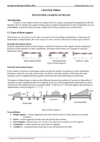
- 1. Strength of Materials I (MEng 1081) Target group: Ext. 1st yr. _______________________________________________________________________________ ________1 Mechanical Engineering Department by Derese.D CHAPTER THREE TRANSVERSE LOADING ON BEAMS Introduction A beam is a bar subject to forces or couples that lie in a plane containing the longitudinal of the bar. Members that are slender and support loadings that are applied perpendicular to their longitudinal axis are called beams. In general, beams are long, straight bars having a constant cross-sectional area. 3.1 Types of Beam support Often beams are classified as to how they are supported and According to determinacy, a beam may be determinate or indeterminate. But in this chapter we only consider statically determinate types of beams. Statically Determinate Beams Statically determinate beams are those beams in which the reactions of the supports may be determined by the use of the equations of static equilibrium. The beams shown below are examples of statically determinate beams. Types of beam supports Statically Indeterminate Beams If the number of reactions exerted upon a beam exceeds the number of equations in static equilibrium, the beam is said to be statically indeterminate. In order to solve the reactions of the beam, the static equations must be supplemented by equations based upon the elastic deformations of the beam. The degree of indeterminacy is taken as the difference between the numbers of reactions to thenumber of equations in static equilibrium that can be applied. In the case of the propped beam shown,there are three reactions R1, R2, and M and only two equations (ΣM = 0 and sum; Fv = 0) can be applied, thus the beam is indeterminate to the first degree (3 – 2 = 1). Types of beam supports Term definition Simple support: - a beam supported on the ends which are free to rotate and have no moment resistance. Fixed: - a beam supported on both ends and restrain from rotation. Over hanging: a beam having one or both of its ends freely extended over the supports. Continuous: - a beam extend over more than two supports. Cantilever: - a projected beam fixed only at one end and free at the other.
- 2. Strength of Materials I (MEng 1081) Target group: Ext. 1st yr. _______________________________________________________________________________ ________2 Mechanical Engineering Department by Derese.D 3.2 Types of Loads Acting On Beams A beam is normally horizontal whereas the external loads acting on the beams is generally in thevertical dir ections. In order to study the behaviors of beams under flexural loads. It becomes pertinentthat one must be familiar with the various types of loads acting on the beams. Loads applied to the beam may consist of a concentrated load (load applied at a point), uniform load,uniformly varying load, or an applied couple or moment. These loads are shown in the figures below. A. Concentrated Load: It is a kind of load which acting at a point on the beam. It represented by a line showing the action of the load and an arrow to show it direction. B. Uniform Load or uniformly distributed (UD) load: is a load distributed or spread over the entire span of beam or over a particular portion of the beam in some specific manner. A. For example, a load of 30KN/m means 30KN force acts over one meter length of the beam. C. Uniformly varying (UV) load: the load intensity varies but varies linearly. Note that at any point x meter from the end, the load intensity is W(x/L) and the total load = WL/2 or the area of triangle representing the UV load. D. Moment or couple load: is represented as shown above by a curved arrow showing the sense of the moment. It is either clockwise (CW) or counter clockwise (CCW). If couple load is acting on a beam, note that reactive forces must be such that they produce a balancing couple. Load intensity In the case of beam load intensity is the load per unit length. Load intensity is infinite for a concentrated (point) load as it acts a point (zero length) UD and UV loads are specified by load intensity as W KN/m. A moment or couple load has zero load intensity. 3.3 Types of supports, loads and reactions Pin support – it prevent translation at the end of the beam but does not prevent rotation. Thus, at the end of A of the beam of (Fig. a), cannot move horizontally or vertically. So, It is capable of developing a force reaction with both horizontal and vertical components (HA& RA)
- 3. Strength of Materials I (MEng 1081) Target group: Ext. 1st yr. _______________________________________________________________________________ ________3 Mechanical Engineering Department by Derese.D -It cannot develop a moment reaction Roller support: At end B of the beam (Fig. a) is prevents translation in the vertical direction but not in the horizontal direction; hence this support can resist a vertical force (RB) but not a horizontal force. Of course, the axis of the beam is free to rotate at B just as it is at A. The vertical reactions at roller supports and pin supports may act either upward or downward, and the horizontal reaction at a pin support may act either to the left or to the right. Fixed support (or clamped support): The beam shown in (Fig. b), is fixed at one end and free at the other. At the fixed support the beam can neither translate nor rotate, whereas at the free end it may do both. Consequently, both force and moment reactions may exist at the fixed support. 3.4. Shearing Force and Bending Moment At every section in a beam carrying transverse loads there will be resultant forces on either side of the section which, for equilibrium, must be equal and opposite, and whose combined action tends to shear the section in one of the two ways shown in Fig. a and b below. The shearing force (S.F) at the section: is equal to the algebraic sum of the forces perpendicular to the axis of the beam either to the left or the right of the section. Bending moment (BM) at the section: is the algebraic sum of the moment of all forces either side of the section. Which side is chosen is purely a matter of convenience but in order that the value obtained on both sides shall have the same magnitude but opposite in direction. 3.4.1. Shearing Force (S.F.) sign convention If the algebraic sum of the forces perpendicular to the axis of the beam calculated from the left is upward or from the right down ward the S.F. is positive, otherwise negative. S.F. sign convention 3.4.2. Bending Moment (B.M.) sign convention Clockwise moments to the left and counterclockwise to the right are positive. Thus Fig. a shows a positive bending moment system resulting in sagging of the beam at x-x and Fig. b illustrates a negative B.M. system with its associated hogging beam.
- 4. Strength of Materials I (MEng 1081) Target group: Ext. 1st yr. _______________________________________________________________________________ ________4 Mechanical Engineering Department by Derese.D It should be noted that the above sign convention for S.F and B.M are somewhat arbitrary and could be completely reversed. Examples Calculating S.F and B.M in beams In statically determinate beams subjected to loads, the reactive forces and moments at the support are determined by using the three conditions of static equilibrium, ΣFV = 0, ΣFH = 0 and ΣM = 0. 1. A simple beam AB supports two loads, a force P and a couple M0, acting as shown in Fig. Find the shear force V and bending moment M in the beam at cross sections located as follows: (a) a small distance to the left of the midpoint of the beam, and (b) a small distance to the right of the midpoint of the beam. Solution Reactions: The first step in the analysis of this beam is to find the reactions RA and RB at the supports. Taking moments about ends B and A gives two equations of equilibrium, from which we find, respectively, (a) Shear force and bending moment to the left of the midpoint. We cut the beam at a cross section just to the left of the midpoint and draw a free-body diagram of either half of the beam. From which we get the shear force: The shear force (at the selected location) is negative and acts in the opposite direction to the assumed direction in FBD. Taking moments about an axis through the cross section where the beam is cut (see Fig. b) gives, => The couple M0 does not act on the free body because the beam is cut to the left of its point of application. (b) Shear force and bending moment to the right of the midpoint. In this case we cut the beam at a cross section just to the right of the midpoint and again draw a free-body diagram of the part of the beam to the left of the cut section (Fig. c). These results show that when the cut section is shifted from the left to the right of the couple M0, the shear force does not change (because the vertical forces acting on the free body do not change) but the bending moment increases algebraically by an amount equal to M0.
- 5. Strength of Materials I (MEng 1081) Target group: Ext. 1st yr. _______________________________________________________________________________ ________5 Mechanical Engineering Department by Derese.D 2. A cantilever beam that is free at end A and fixed at end B is subjected to a distributed load of linearly varying intensity q (Fig. a). The maximum intensity of the load occurs at the fixed support and is equal to q0. Find the shear force V and bending moment M at distance x from the free end of the beam. Solution Shear force (S.F) Free body diagram, assuming V and M are positive. The intensity of the distributed load at distance x from the end is Therefore, the total downward load on the free body, equal to the area of the triangular loading diagram (Fig. b), is From an equation of equilibrium in the vertical direction we find, At the free end A (@ x = 0) the shear forces are zero and at the fixed end B (x= L) the shear force has its maximum value: Bending moment (B.M). Recalling that the moment of a triangular load is equal to the area of the loading diagram times the distance from its centroid to the axis of moments, we obtain the following equation of equilibrium (counterclockwise moments are positive). from which we get, (a) At the free end of the beam (x = 0), the bending moment is zero, and at the fixed end (x = L) the moment has its numerically largest value: (b) The minus signs in Eqs. (a) And (b) show that the bending moments act in the opposite direction to that shown in Fig. b. 3. Determine the shear force V and bending moment M at the midpoint C of the simple beam AB shown in the figure. Solution Determine reaction forces, RA and RB from FBD.
- 6. Strength of Materials I (MEng 1081) Target group: Ext. 1st yr. _______________________________________________________________________________ ________6 Mechanical Engineering Department by Derese.D ΣMA = 0, assume ccw positive. - 6KNx1m – 2KN/m(2m)x3m + RBx4m = 0 RB = 4.5KN ΣFV = 0: RA – 6k – 2KN/m (2m) + RB = 0 RA = 5.5KN To find shear force and BM. Section at c ΣFV = 0: RA – 6K – V = 0 V = 5.5 – 6 = - 0.5KN ΣMC = M – RAx2m + 6kx1m = 0 M = 5 KN.m Example 4 cantilever beam 3.5 Relationship between Load, Shear, and Moment The vertical shear at C in the figure shown in section is taken as If we differentiate M with respect to x: Thus, Thus, the rate of change of the bending moment with respect to x is equal to the shearing force, or the slope of the moment diagram at the given point is the shear at that point. Differentiate V with respect to x gives
- 7. Strength of Materials I (MEng 1081) Target group: Ext. 1st yr. _______________________________________________________________________________ ________7 Mechanical Engineering Department by Derese.D Thus, the rate of change of the shearing force with respect to x is equal to the load or the slope of the shear diagram at a given point equals the load at that point. 3.6 Shear and Moment Diagrams Because of the applied loadings, beams develop an internal shear force and bending moment that, in general, vary from point to point along the axis of the beam. In order to properly design a beam it therefore becomes necessary to determine the maximum shear and moment in the beam. One way to do this is to express V and M as functions of their arbitrary position x along the beam’s axis. These shear and moment functions can then be plotted and represented by graphs called shear and moment diagrams. The maximum values of V and M can then be obtained from these graphs. Procedure for analysis for Analysis The shear and moment diagrams for a beam can be constructed using the following procedure. Support Reactions. Determine all the reactive forces and couple moments acting on the beam, and resolve all the forces into components acting perpendicular and parallel to the beam’s axis. Shear and Moment Functions. Specify separate coordinates x having an origin at the beam’s left end and extending to regions of the beam between concentrated forces and/or couple moments, or where there is no discontinuity of distributed loading. Section the beam at each distance x, and draw the free-body diagram of one of the segments. Be sure V and M are shown acting in their positive sense, The shear is obtained by summing forces perpendicular to the beam’s axis. To eliminate V, the moment is obtained directly by summing moments about the sectioned end of the segment. Shear and Moment Diagrams Plot the shear diagram (V versus x) and the moment diagram (M versus x). If numerical values of the functions describing V and M are positive, the values are plotted above the x axis, whereas negative values are plotted below the axis. Generally it is convenient to show the shear and moment diagrams below the free-body diagram of the beam. Example 1. Draw the shear force (S.F) and bending moment (B.M) for the beam loaded as show Solution Reaction forces: Shear force and bending moment between segments
- 8. Strength of Materials I (MEng 1081) Target group: Ext. 1st yr. _______________________________________________________________________________ ________8 Mechanical Engineering Department by Derese.D S.F and B.M diagram Example 2 Draw the shear force and B.M diagram for fig shown below.
- 9. Strength of Materials I (MEng 1081) Target group: Ext. 1st yr. _______________________________________________________________________________ ________9 Mechanical Engineering Department by Derese.D Example 3 A beam ABC with an overhang at one end supports a uniform load of intensity 12 kN/m and a concentrated load of magnitude 2.4 kN (see figure). Draw the shear-force and bending-moment diagrams for this beam. Solution Example 4 The cantilever beam AB shown in the figure is subjected to a uniform load acting throughout one-half of its length and concentrated load acting at the free end. Draw the shear-force and bending-moment diagrams for this beam. Solution
- 10. Strength of Materials I (MEng 1081) Target group: Ext. 1st yr. _______________________________________________________________________________ ________10 Mechanical Engineering Department by Derese.D Example 5 Draw the shear-force and bending-moment diagrams for a cantilever beam AB supporting a linearly varying load of maximum intensity q0 (see figure). Solution Example 6 Beam ABCD is simply supported at B and C and has overhangs at each end (see figure). The span length is L and each overhang has length L/ 3. A uniform load of intensity q acts along the entire length of the beam. Draw the shear-force and bending-moment diagrams for this beam. Solution
- 11. Strength of Materials I (MEng 1081) Target group: Ext. 1st yr. _______________________________________________________________________________ ________11 Mechanical Engineering Department by Derese.D Work sheet Draw S.F and B.M diagram for the beams shown below. 1. 2. 3. 4. 3 and 4 are assignments _____________________________