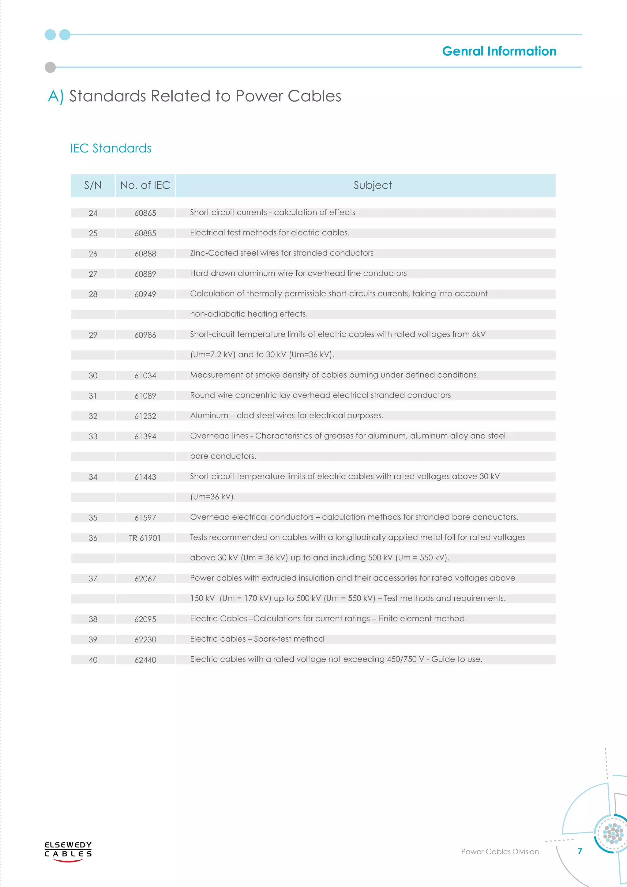
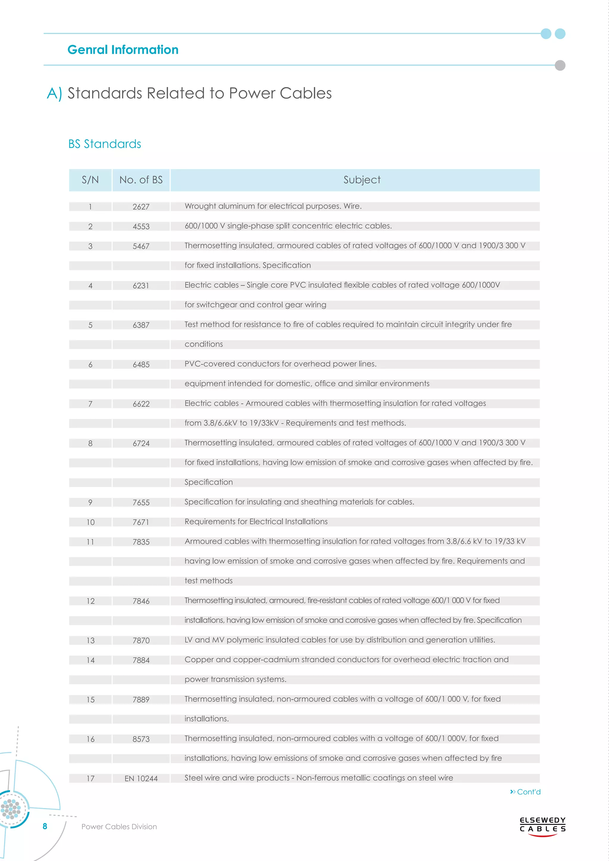
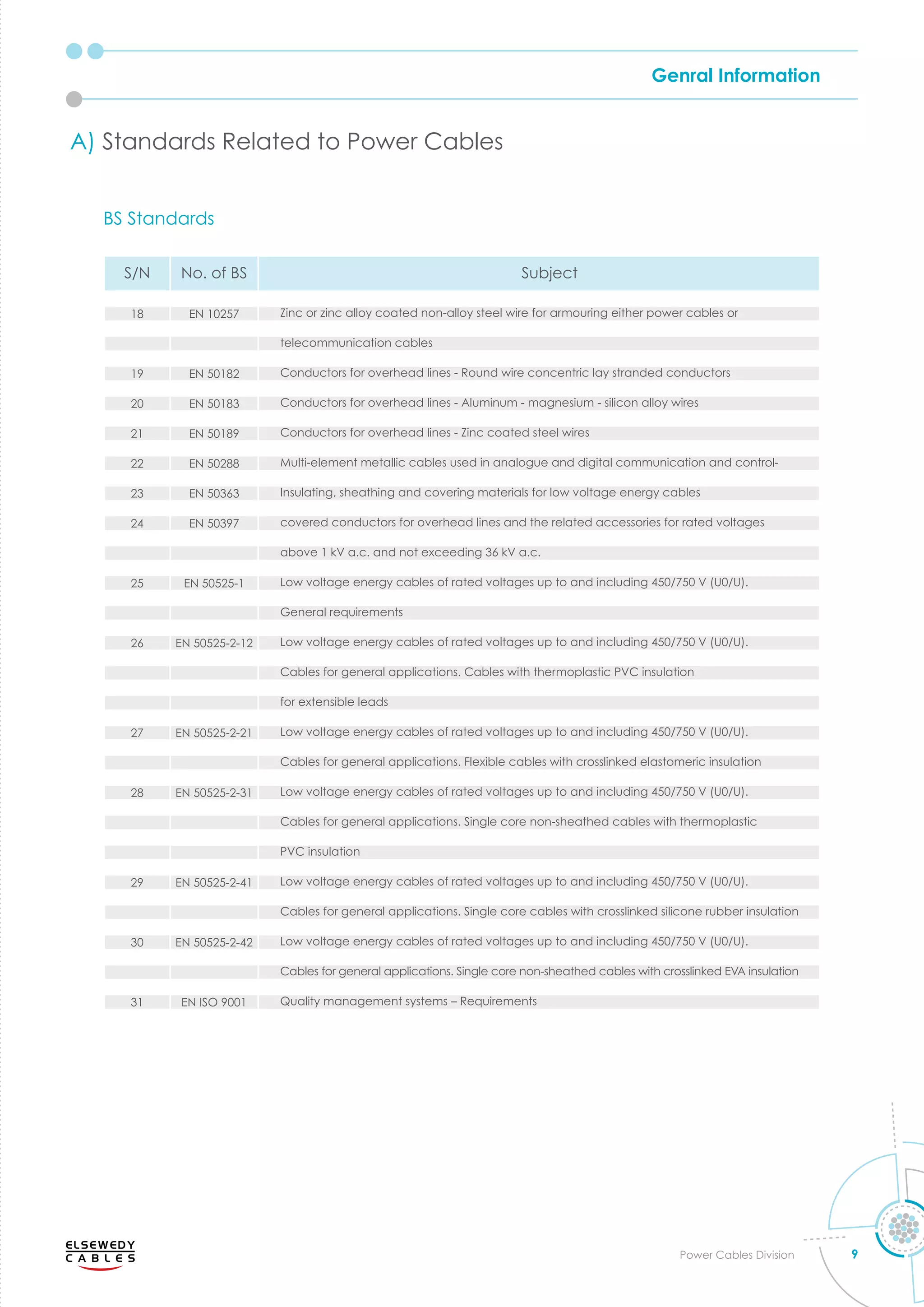
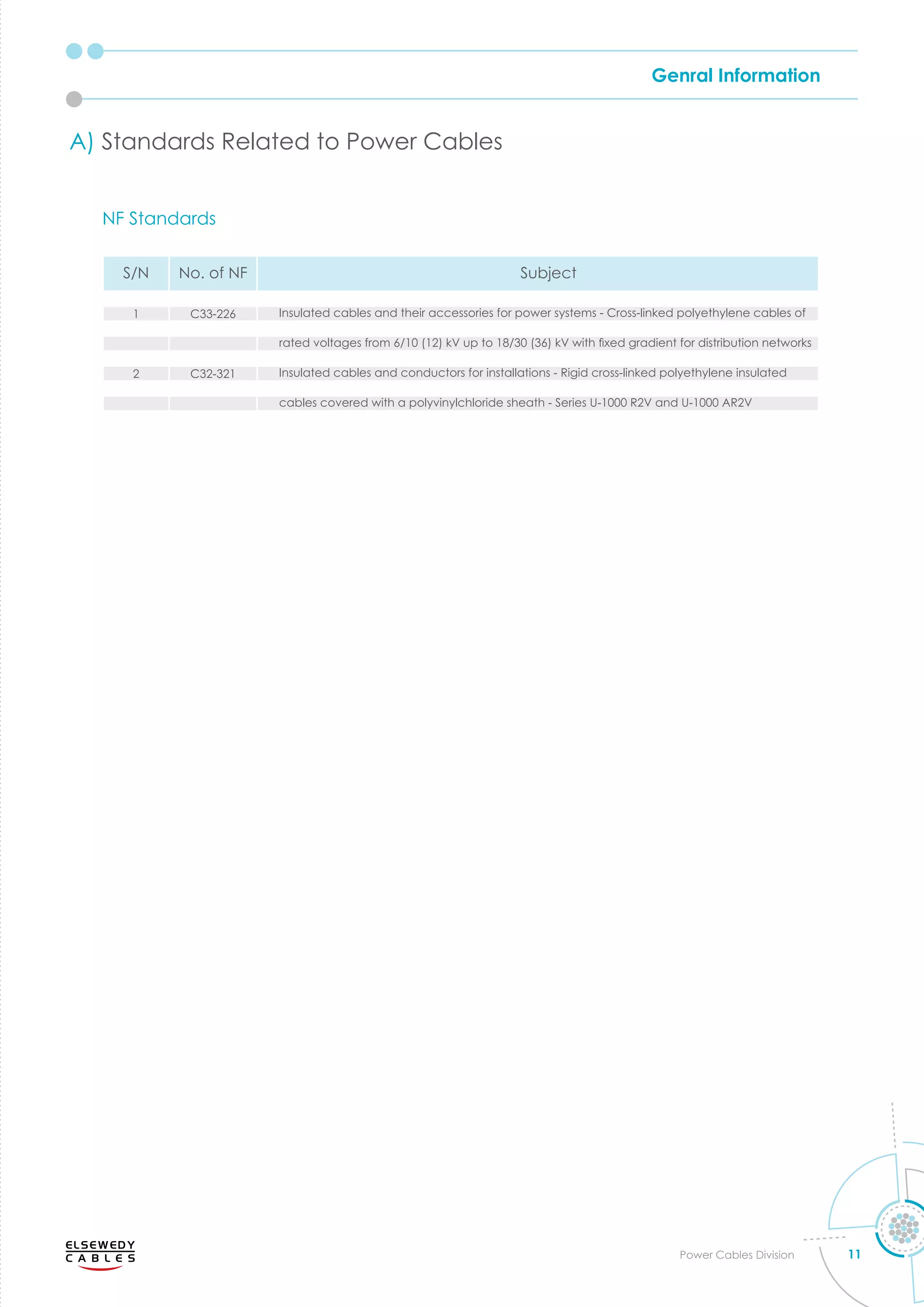
This document provides an overview of a catalog that contains technical information on overhead conductors and electrical power cables up to 220 kV. The catalog helps customers select suitable cables based on factors like voltage, current rating, short circuit current, weight and dimensions. Standards from organizations like IEC and BS that relate to power cables are also listed.


![Genral Information
14 Power Cables Division
1. Resistance
The conductor DC resistance values given in this
catalog are based on C. in case of the conductor
DC resistance is required at different temperature, the
following formula shall be used:
Rθ
= R20
[ 1 + θ(θ-20)] Ω/Km
where
Rθ
: conductor DC resistance at θ C m
R20
conductor C resistance at C m
θ o erating tem erature C
α tem erature coefficient C
= 0.00393 for Copper
= 0.00403 for Aluminum
To get AC resistance of the condcutor at operating
temperature the following fromula is used
m
where
Yp
and Ys
are proximity and skin effect factors
respectively
2. Inductance:
The self and mutual inductances are formoualted as
following:
mh/Km
where
L : Inductance mh/Km
K : Constant (as self inductance)
d : Conductor diameter mm
S : Axial spacing between cables in mm
trefoil and in case of at formation
multiply the spacing by 1.26
3. capacitance:
The capacitance is formulated as following:
μf/Km
where
C : Capacitance μf/Km
εr
: relative permittivity of insulation
material
D : Diameter over Insulation mm
d : Diameter under insulation mm
4. Insulation resistance:
The insulation resistance is formualted as following:
m
where
insulation resistance m
K : Constant depending on the
insulation material
d : diameter under the insulation mm
D : diameter over the insulation mm
5. Charging Current:
The charging current is the capacitive current which
o s through the dielectric la ers hen C oltage
is applied. The value can be calculated from the
following equation:
A/Km
where
Ic
: Charging current A/Km
U0
: Rated phase voltage V
ω : Angular of velocity (2πf)
f : Frequency Hz
C : Capacitance μf/Km
6. Dielectric losses
The dielectric losses of an AC cable are proportional
to the capacitance, the frequency, the phase voltage
squared and the power factor. The value can derived
from the following equation:
watt/Km/phase
where
Wd : Dielectric losses watt/Km/phase
f : Frequency Hz
C : Capacitance μf/Km
U0
: Rated phase voltage V
tanδ : Dielectric power factor
ω : Angular of velocity (2πf)
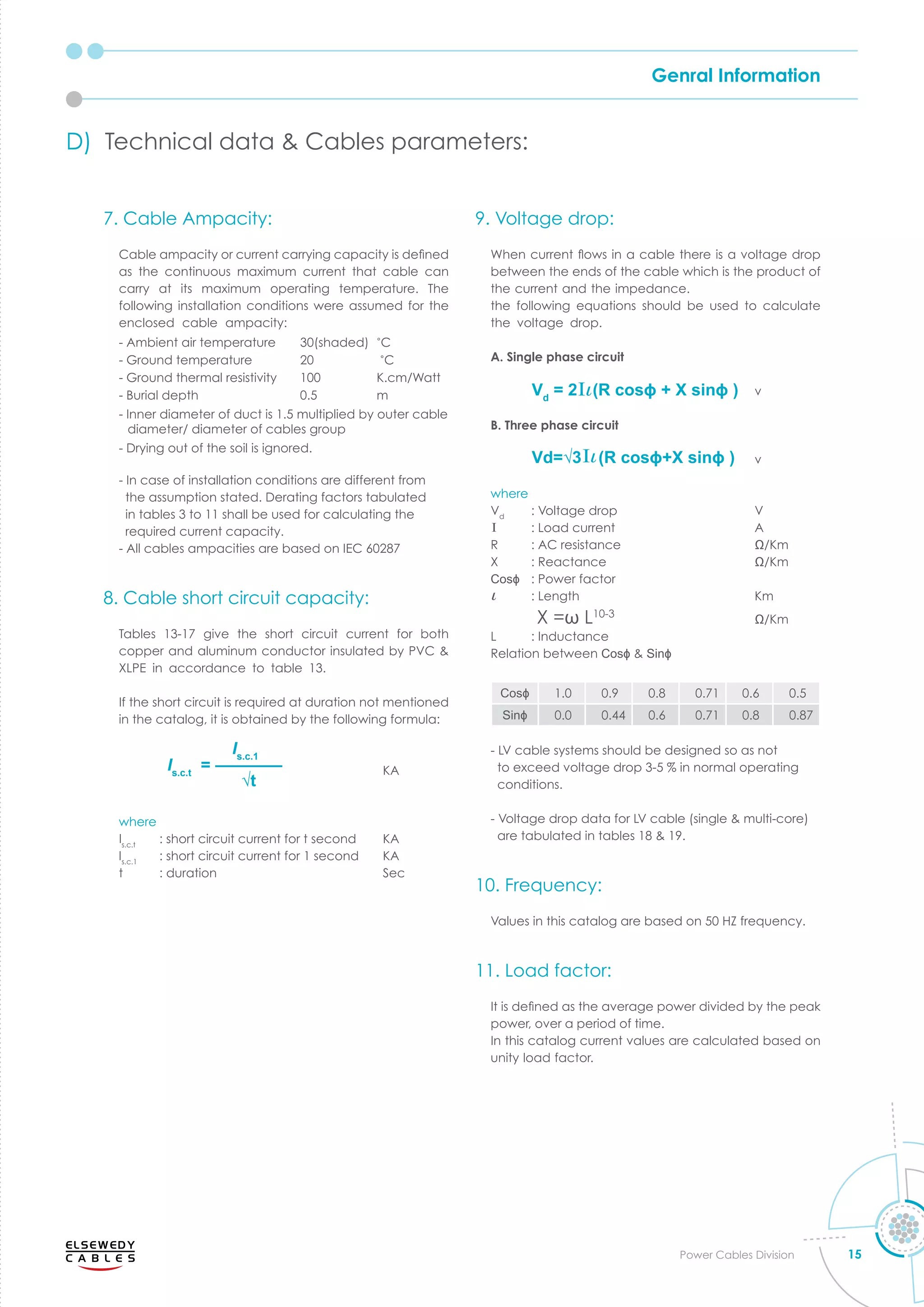
D) Technical data Cables arameters
L = K + 0.2 In( )
2S
d
—
C = ———————
18 In( )
D
d
—
εr
RAC
= Rθ
(1 + Yp
+ Ys
)
Rθ
= R20
[ 1 + α(θ-20)] Ω/Km
R = K ln(D/d)
Ic
= U0
ωC10-6
Wd
= ωCU0
2
tanδ 10-6](https://image.slidesharecdn.com/power-cables-catalogueelsewedy-221016110122-e67b5b58/75/power-cables-catalogue-Elsewedy-pdf-15-2048.jpg)