
Recommended
More Related Content
What's hot
What's hot (20)
Similar to Gps
Similar to Gps (20)
Recently uploaded
Recently uploaded (20)
Gps
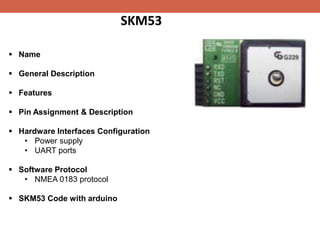
- 1. SKM53 Name General Description Features Pin Assignment & Description Hardware Interfaces Configuration • Power supply • UART ports Software Protocol • NMEA 0183 protocol SKM53 Code with arduino
- 2. SKM53 Name: The Ultra High Sensitivity and the Smart Antenna GPS Module. General Description : • embedded GPS antenna. • high performance navigation. • solid fix . • high performance features of the MediaTek 3339 single-chip architecture. • Sensitivity. • The 6-pin UART connector design. Features: • Ultra high sensitivity: -165dBm • 22 tracking/66 acquisition-channel receiver • NMEA protocols (default speed: 9600bps) • WAAS/EGNOS/MSAS/GAGAN support • Embedded patch antenna • Tiny form factor • Operating temperature range: -40 to 85℃
- 3. Pin Assignment & Description Hardware Interfaces Configuration: • Power supply: The input voltage Vcc should be 5V. Suitable decoupling provided by external decoupling circuitry (10uF and 1uF). reduce the Noise. increase power stability.
- 4. Hardware Interfaces Configuration con’t: • UART ports: supports one full duplex serial channels UART. The serial connections are at 2.85V LVTTL logic levels. the data format is however fixed: X, N, 8, 1. The modules default baud rate is set up 9600bps. The RXD0 & TXD0 recommended to pull up (10KΩ). It can increase the stability of serial data. Software Protocol: • NMEA 0183 Protocol:
- 5. SKM53 Code with arduino
- 6. RFID Radio Frequency Identification Definition RFID technology race-timing, DVD kiosks, asset tracking and tool tracking. Requirements Frequency ranges RFID Tags antenna & RFID chip RFID Antennas RFID Readers RFID Setup
- 7. Definition Radio-frequency identification (RFID) is the wireless non-contact use of radio-frequency electromagnetic fields to transfer data for the purposes of automatically identifying and tracking tags attached to assets. RFID technology Is used in hundreds of applications such as race-timing, DVD kiosks, asset tracking, and tool tracking. Requirements readers, antennas, and tags The selection of ancillary items such as cables, mounting brackets, and GPIO devices will greatly impact the effectiveness of an RFID system.
- 8. Frequency ranges There are three primary frequency ranges used in RFID: Within the UHF Frequency range of 856 – 960 MHz, there are two primary subsets: a) The FCC (US) standard frequency range of 902-928 MHz b) The ETSI (EU) standard frequency range of 865-868 MHz RFID LF (Low Frequency) Frequency: 125 - 134 kHz Typical Use: Animal identification. Range: Contact up to 10 cm HF (High Frequency) Frequency: 13.56 MHz Typical Use: NFC, smart cards, tickets, and DVD kiosks. Range: Near contact up to 30 cm. UHF (Ultra-High Frequency) Frequency: 433 MHz & 856 - 960 MHz Typical Use: Used in all types of applications. Range: Tag dependent; Near contact up to 100+ meters.
- 9. RFID Tags is comprised of two parts – an antenna for transmitting and receiving signals, and an RFID chip (or integrated circuit) which stores the tag’s ID and other information RFID tag selection is based upon the application. Example: Metal-mount RFID tags are specially designed to read well when mounted on a metallic surface, whereas RFID wet inlays or RFID labels are not readable if applied to metal surfaces. RFID Antennas RFID Antennas are a necessary element in any RFID system; however, they are dumb devices which use power from the reader to generate a field allowing the reader to transmit and receive signals from the RFID tags
- 10. RFID Readers • An RFID reader is the brain of the RFID system and necessary for any system to function. Readers, also called interrogators, are devices that transmit and receive radio waves in order to communicate with RFID tags. RFID readers fall into several classes – fixed RFID readers, handheld RFID readers, and integrated RFID readers. Which one you choose will depend on how and where you deploy the reader. RFID setup RFID reader