Call Girls Service Nagpur Tanvi Call 7001035870 Meet With Nagpur Escorts
Msc.1 circ.1367
1. I:CIRCMSC011367.docx
E
4 ALBERT EMBANKMENT
LONDON SE1 7SR
Telephone: +44 (0)20 7735 7611 Fax: +44 (0)20 7587 3210
Ref. T2-OSS/1.4 MSC.1/Circ.1367
24 May 2010
AMENDMENTS TO THE INTERNATIONAL AERONAUTICAL
AND MARITIME SEARCH AND RESCUE (IAMSAR) MANUAL
1 The Maritime Safety Committee (MSC), at its eighty-seventh session
(12 to 21 May 2010), having been informed that the International Civil Aviation Organization
(ICAO) had approved the amendments to the IAMSAR Manual prepared by the ICAO/IMO Joint
Working Group on Harmonization of Aeronautical and Maritime Search and Rescue, and that
they had been endorsed by the Sub-Committee on Radiocommunications and Search and
Rescue (COMSAR) at its fourteenth session, approved the annexed amendments in accordance
with the procedure laid down in resolution A.894(21).
2 The Committee decided that the amendments should become applicable
on 1 June 2011.
***
2.
3. MSC.1/Circ.1367
Annex, page 1
I:CIRCMSC011367.docx
ANNEX
SECTION I
AMENDMENTS TO IAMSAR MANUAL – VOLUME I
1 Abbreviations and Acronyms
- Add the following text on page vii:
AIS ………… Automatic Identification System
LRIT ……..... Long Range Identification and Tracking
- Add the following text on page viii:
SRS ………. Ship Reporting System
VMS ………. Vessel Monitoring System
VTS ………. Vessel Traffic Services
2 Glossary
- Add the following text on page ix:
Automatic Identification System (AIS) A system used by ships and vessel traffic
services (VTS), principally for identifying and locating vessels.
Geographic Information System (GIS) A system which captures, stores,
analyses, manages and presents data that is linked to location.
Long Range Identification and Tracking (LRIT) A system which requires certain
vessels to automatically transmit their identity, position and date/time
at 6-hour intervals in accordance with SOLAS regulation V/19-1.
Maritime Domain Awareness (MDA) The effective understanding of any activity
associated with the maritime environment that could impact upon the security,
safety, economy or environment.
Ship Reporting System (SRS) Reporting systems which contribute to safety of
life at sea, safety and efficiency of navigation and/or protection of the marine
environment. They are established under SOLAS regulation V/11 or for SAR
purposes under chapter 5 of the International Convention on Maritime Search and
Rescue, 1979.
Vessel Tracking A generic term applied to all forms of vessel track data derived
from multiple sources such as ship reporting systems, AIS, LRIT, SAR aircraft,
VMS and VTS.
Vessel Monitoring System (VMS) A tracking system which provides for
environmental and fisheries regulatory organizations to monitor the position, time
at a position, course and speed of commercial fishing vessels.
4. MSC.1/Circ.1367
Annex, page 2
I:CIRCMSC011367.docx
Vessel Traffic Services (VTS) A marine traffic monitoring system established by
harbour or port authorities to keep track of vessel movements and provide
navigational safety in a limited geographical area.
3 Chapter 2
- Add the following text in paragraph 2.3.7, Table, "Desired" column:
- Vessel tracking information including: AIS, LRIT, VMS and SRS
- Add the following text in paragraph 2.7.2, at the end of first sentence after "search
plan":
- and gaining access to vessel tracking information such as AIS, LRIT, VMS
used by fisheries and Ship Reporting Systems (SRS).
4 Chapter 3
- Add the following text in paragraph 3.2.11, at the bottom of second column:
- Vessel tracking systems (AIS, LRIT, VMS)
5 Chapter 4
- Delete the last sentence on page 4-4 (a), which reads:
- "Satellite beacons have demonstrated superior performance to those that alert
on 121.5 MHz"
- Amend the title of paragraph 4.5.25 by adding after "Ship Reports for SAR":
- "and Vessel Tracking"
- Add new paragraph after paragraph 4.5.26:
"4.5.27 As well as ship reporting systems, other vessel tracking systems and
services are valuable for search and rescue. AIS, LRIT, VMS and Vessel Traffic
Services (VTS) are all valuable sources of vessel position data and can be
displayed to provide a surface picture (SURPIC). The surface picture can assist in
the identification and location of suitable rescue vessels and be used to locate
potential rescue vessels. In accordance with SOLAS regulation V/19-1,
Contracting Governments should make provision to receive LRIT vessel position
data for SAR in accordance with applicable IMO guidance."
6 Chapter 5
- Add in paragraph 5.4.4, dash point 7, after "ship reporting systems":
- and vessel tracking systems
5. MSC.1/Circ.1367
Annex, page 3
I:CIRCMSC011367.docx
7 Chapter 6
- Add in paragraph 6.5.3, after dash point 3, new dash point:
"- provide access to ship reporting and vessel tracking systems (AIS, LRIT,
VMS, VTS)"
8 Appendix C
- Add in paragraph C.5.2, third sentence, after "Ship reporting systems":
"- and vessel tracking systems enable"
9 Appendix G
- Delete in paragraph G.6.1 the second dash point referring to Inmarsat-E.
- Reword G.6.1 to read:
- Maritime Satellite Emergency Position Indicating Radio Beacons (EPIRBs)
have been accepted into the GMDSS. These beacons operate on 406 MHz and
may have a 121.5 MHz final homing signal. The signals are relayed via
Cospas-Sarsat satellites, local user terminals (LUTs) and mission control
centres (MCCs) to SAR Points of Contact (SPOCs) which include RCCs.
- Delete the second sentence of paragraph G.6.2.
- Delete in paragraph G.7.2, third sentence:
- "A" and "E (E is the EPIRB)"; and
- Add in paragraph G.7.2, third sentence:
- "Mini-C" and "F77".
6. MSC.1/Circ.1367
Annex, page 4
I:CIRCMSC011367.docx
SECTION II
AMENDMENTS TO THE IAMSAR MANUAL – VOLUME II
1 Content
- Add on page vii (new last appendix):
- Appendix [X] Search Planning for 121.5 MHz Distress Beacon Alerts
2 Abbreviations and Acronyms
- Add the following text on page ix:
"AIS ………. Automatic Identification System"
- Add the following text on page xi:
"LRIT …….. Long Range Identification and Tracking"
- Add the following text on page xiii:
"SRS ……… Ship Reporting System"
- Add the following text on page xiv:
"VMS ……… Vessel Monitoring System
VTS ……….. Vessel Traffic Services"
3 Glossary
- Add the following text on page xv:
"Automatic Identification System (AIS) A system used by ships and vessel
traffic services (VTS), principally for identifying and locating vessels.
Geographic Information System (GIS) A system which captures, stores,
analyses, manages and presents data that is linked to location.
Long Range Identification and Tracking (LRIT) A system which requires certain
vessels to automatically transmit their identity, position and date/time at 6-hour
intervals in accordance with SOLAS regulation V/19-1.
Maritime Domain Awareness (MDA) The effective understanding of any activity
associated with the maritime environment that could impact upon the security,
safety, economy or environment.
Ship Reporting System (SRS) Reporting systems which contribute to safety of
life at sea, safety and efficiency of navigation and/or protection of the marine
environment. They are established under SOLAS regulation V/11 or for
SAR purposes under chapter 5 of the International Convention on Maritime Search
and Rescue, 1979.
7. MSC.1/Circ.1367
Annex, page 5
I:CIRCMSC011367.docx
Vessel Tracking A generic term applied to all forms of vessel track data derived
from multiple sources such as ship reporting systems, AIS, LRIT, SAR aircraft,
VMS and VTS.
Vessel Monitoring System (VMS) A tracking system which provides for
environmental and fisheries regulatory organizations to monitor the position, time
at a position, course and speed of commercial fishing vessels.
Vessel Traffic Services (VTS) A marine traffic monitoring system established by
harbour or port authorities to keep track of vessel movements and provide
navigational safety in a limited geographical area."
4 Chapter 1
- Add on page 1-4 to heading "Ship Reporting System":
"- and Vessel Tracking"
- Add new paragraph 1.3.6:
"1.3.6 As well as ship reporting systems (SRS), RCCs can use vessel position
data from various vessel tracking systems to support SAR operations. These may
include the Long-range Identification and Tracking (LRIT) system, the Automatic
Identification System (AIS) system, fisheries and other Vessel Monitoring Systems
(VMS) and Vessel Traffic Services (VTS) established to monitor port operations or
to cover focal areas or sensitive areas. Data from each of these systems can be
displayed by RCCs using Geographic Information Systems (GIS) to produce
a surface picture (SURPIC). SURPICS can be used to identify and locate potential
rescue vessels as well as improve maritime domain awareness (MDA).
In accordance with SOLAS regulation V/19-1, Contracting Governments should
make provision to receive LRIT vessel position data for SAR. In accordance with
IMO guidance material, RCCs can request LRIT data for SAR operations within
their own SRR and for SAR coordination requirements outside it as appropriate.
Data on all vessels can be requested within a circular or rectangular area at no
charge to the RCC."
- Add in paragraph 1.3.11, to final sentence:
"- and operate on 406 MHz and 121.5 MHz for final homing."
- Add in paragraph 1.8.15, to "Ship reporting systems for SAR":
"- and Vessel tracking (AIS, LRIT, VMS and VTS)"
- Add new paragraph after paragraph 1.11.9:
"1.11.10 Display of Vessel Tracking Data
A computer system with Geographic Information System (GIS) display
capability is important for displaying vessel tracking data sourced from
AIS, LRIT, VMS, VTS and other sources. The location of SAR Units can
also be tracked and displayed, as can search areas and other
information."
8. MSC.1/Circ.1367
Annex, page 6
I:CIRCMSC011367.docx
5 Chapter 2
- Delete in paragraph 2.6.1 the second dash point about Inmarsat-E.
- Reword the remainder of paragraph 2.6.1 to read:
"- Maritime Satellite Emergency Position Indicating Radio Beacons (EPIRBs)
have been accepted into the GMDSS. These beacons operate on 406 MHz and
may have a 121.5 MHz final homing signal. The signals are relayed via
Cospas-Sarsat satellites, local user terminals (LUTs) and mission control
centres (MCCs) to SAR Points of Contact (SPOCs) which include RCCs."
- Amend second sentence of paragraph 2.6.3 as follows:
"- Signals are also relayed via over flying aircraft and satellite from 121.5 and
243 MHz ELTs and EPIRBs, but signals from these beacons are not
processed by satellites and are not not specifically designed for satellite
compatibility nor considered part of GMDSS."
- Delete final sentence in brackets of paragraph 2.6.6.
- Delete whole paragraph 2.6.9.
- Renumber paragraph 2.6.10 as 2.6.9.
- Delete whole paragraph 2.6.11.
- Renumber paragraph 2.6.12 as 2.6.10.
- Delete in paragraph 2.7.6 at start of first sentence after the word Inmarsat:
- "-A and" At the end of the last sentence, Delete: "and E (E is the EPIRB)" and
Add after the letter "M" ", Mini-C and F77."
- Delete in paragraph 2.9.2 second sentence about Inmarsat-E.
- Amend in paragraph 2.9.4 the first sentence to read:
"- Many civil aircraft worldwide, especially operating over ocean areas, carry an
ELT which operates on 406 MHz for alerting and 121.5 MHz for final homing."
- Delete in paragraph 2.9.4, third sentence, the words:
- "alert and", so that the sentence reads: "Many ELTs also provide homing
signals on 243 MHz ..."
- Delete in paragraph 2.9.4 the final sentence.
- Amend in paragraph 2.9.7 the first sentence to read:
"- When carried aboard vessels or other craft, EPIRBs can send signals
on 406 MHz for alerting and 121.5 and 243.0 MHz for final homing."
- Delete in paragraph 2.9.7 the final sentence.
9. MSC.1/Circ.1367
Annex, page 7
I:CIRCMSC011367.docx
- Amend in paragraph 2.13.1 the end of the first sentence to read:
"- … or a seven or nine digit identity for Inmarsat terminals."
- Delete in paragraph 2.13.1 the second last sentence.
- Add at the end of paragraph 2.13.2 the following:
- MMSIs are also used in the AIS for vessels, base stations, aids to navigation,
SAR aircraft and AIS SARTs. The various platforms can be differentiated by
reference to the MMSI format and from databases.
- Add new paragraph after paragraph 2.32.4:
"2.33 Vessel Tracking Communications
Various forms of communication can be used for vessel tracking. Ship
reporting systems can use voice reporting over VHF and HF, DSC and
Inmarsat. Many ship reporting systems use Inmarsat-C polling or
Inmarsat automated position reporting (APR). AIS uses a time-division
multiple access (TDMA) scheme to share the VHF frequency, also known
as the VHF Data Link (VDL). There are two dedicated frequencies used
for AIS – AIS 1 (161.975 MHz) and AIS 2 (162.025 MHz). LRIT can
employ any form of communication which meets the required functional
specification, but most vessels use Inmarsat equipment to report every
six hours to their Data Centre via a communications provider and
application service provider. Vessel Monitoring Systems (VMS) can use
various systems for tracking, including Inmarsat, Iridium and Argos."
6 Chapter 3
- Add in paragraph 3.5.3(b), second paragraph, after the words "ship reporting
systems":
- "and vessel tracking systems."
- Add in paragraph 3.5.9(c) a second sentence as follows:
"- Check vessel tracking systems (AIS, LRIT, VMS, VTS) for vessels which may
be able to assist."
7 Chapter 5
- Renumber existing subparagraph 5.6.4(b) as 5.6.4(c).
- Add new subparagraph 5.6.4(b):
"5.6.4(b) When reports are received of detections of 121.5 MHz or 243 MHz from
over flying aircraft (these signals are not processed by Cospas-Sarsat),
a search area will need to be established so that an electronic search
can be conducted for the beacon. Appendix [X] can be used for
guidance on determining a search area and how that area should be
searched."
10. MSC.1/Circ.1367
Annex, page 8
I:CIRCMSC011367.docx
8 Appendix B
- Delete on Page B-7 "Sample 121.5 MHz Initial Alert" and the format.
- Delete on Page B-10 "Inmarsat-E Format".
9 Add new last appendix:
Appendix R
Search Planning for 121.5 MHz Distress Beacon Alerts
1. Searching for beacons is often difficult, and may be impossible without additional
information. However, the methods in this Appendix should be followed as practicable.
2. Search planning for 121.5 MHz beacon alerts typically result from reports received from
commercial aircraft flying at high altitude. The beacon could be located anywhere
within a large search area. Reports might also be received via low-flying aircraft and
ground stations. The methods that follow will help define and reduce beacon search
areas. Maximum detection ranges for beacon signals are assumed to be limited by
line-of-sight.
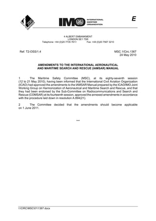
3. Figure 1 depicts the geometry when an aircraft receives a beacon signal, and shows
labelling used in planning a search for the beacon. However, potential scenarios
discussed in the cautionary notes below may limit the applicability of Figure 1 and
should be taken into account when deemed appropriate.
CAUTIONARY NOTES:
Only a single report and reporting aircraft location might be received. Unless the aircraft
can provide additional information, the search area would have to be assumed to include the
area within a single circle centred on the reporting aircraft's location.
Reports of first heard and last heard information may not be accurate. The person
monitoring the radio may not immediately hear or recognize the 121.5 MHz distress beacon
swept tone, causing the reported time and location to be incorrect.
● The beacon may have started transmitting after the reporting aircraft was already well
within the maximum detection range, or the beacon may cease transmitting well before
the aircraft is beyond the maximum detection range. Try to determine whether the
signal: seemed strong when first acquired and then faded; was getting stronger and
then abruptly ceased; or started suddenly, stopped suddenly, and seemed to be about
the same strength the whole time it was heard. In such cases, the search planning
procedure in this Appendix should still work, although the overlapping area where the
two circles intersect will be enlarged; the centres of the circles would be closer together
than they would be if signal acquisition and loss were solely due to the reporting aircraft
coming within and then moving beyond maximum detection range while the beacon
was transmitting.
11. MSC.1/Circ.1367
Annex, page 9
I:CIRCMSC011367.docx
● As a part of the report data gathering process it should also be ascertained that the
receiving radio was already on (did not receive the signal when it was first turned on)
and that detection of the signal did not occur while squelch was being adjusted. These
situations may occur when seeking reports from additional aircraft when they first turn
on or adjust their radios to listen. In such cases, the position for the last heard point
could be more useful that the position of when the beacon was first heard.
Reports from a single aircraft may occur at different altitudes or courses. Aircraft,
particularly those under instrument flight rules, may be ascending, descending and/or changing
course according to their flight plan and air route traffic control needs. The first heard and last
heard reports could be from different altitudes or on different courses. For a course change,
knowing the turn point would allow drawing another range circle to combine with the first heard
and last heard generated range circles to more narrowly define the area. When the reports
occur at different altitudes, range circles should be drawn for each altitude to identify their
intersect points.
The transmitting beacon antenna may have some height above sea level or above its
surrounding terrain. The height of the sending antenna should be added to the height of the
radio receiver when estimating the detection range.
In areas involving an island, the island should be considered as a possible forced landing
site. The first heard and last heard positions may be affected by the forced landing site's
altitude and the terrain surrounding the site, which could block the signal in some directions.
The radio horizon range circle may cross land. The altitude of the reporting aircraft should
be assumed to be the aircraft altitude above that elevation of the terrain at the lowest land
horizon rather than above sea level, as discussed below in this Appendix.
The detected beacon may be aboard an in-flight aircraft, and the aircraft, course, speed or
altitude could change. The procedures in this Appendix do not account for an in-flight beacon
scenario, but the search planner should be aware that apparently conflicting data or unexpected
search planning outcomes could be caused by this situation.
Figure 1 – Geometry where reporting aircraft passes within reception
range of beacon signal
12. MSC.1/Circ.1367
Annex, page 10
I:CIRCMSC011367.docx
SEARCH PLANNING PROCEDURE
4. Record reported data. Use Table 1 to record data received about
a transmitting 121.5 MHz beacon. Of all data collected about the beacon signal, the
position and height of the receiving antenna for points first heard (PFH) and last heard
(PLH) are most important.
Note: Obviously, reports from multiple sources can help substantially in narrowing
down the search area for a 121.5 MHz beacon. The SAR Mission Coordinator (SMC)
should use all reports, and also solicit additional reports from other aircraft in the area,
either directly or via the appropriate flight services as appropriate. Aircraft should be
asked to report their own altitudes and positions where the signal was first heard, when
the maximum signals were heard, and when the signal faded or was lost.
Flight services, communications authorities, maritime SAR authorities or others might
also be able to obtain fixes or bearings on activated beacons. When receiving multiple
reports, consider the possibility that more than one activated 121.5 MHz beacon might
be heard. The authorities might also be able to help locate and silence an inadvertently
activated beacon.
Point
Date-
Time
Position
(lat/long)
Aircraft Altitude
(h)
(ft)
Course
(degrees
true)
PFH
(first
heard)
N/S
E/W
PLH
(last
heard)
N/S
E/W
Table 1 – 121.5 MHz beacon alert report data
5. Plot the reporting aircraft track. Use a rhumb line or great circle navigation
depending on the track being followed by the reporting aircraft, as depicted in Figure 2.
NOTE: The geographic area used as an example in Figures 2, 3, 4, 5, 8 and 10
is Hawaii and the surrounding area. The illustration shows a Lockheed C-130 search
aircraft from Air Station Barbers Point in response to a report from an aircraft at
high altitude, but similar plots could be developed for any area and other situations.
13. MSC.1/Circ.1367
Annex, page 11
I:CIRCMSC011367.docx
Figure 2 – Plot of PFH and PLH
6. Plot the radio horizons. Compute and plot the distance to the radio (VHF/UHF)
horizon for the reporting aircraft at PFH and PLH.
a. The radio horizon distance is estimated using Table 3 at the end of this
appendix or by using the following equation:
h1.23d
Where:
h is the antenna height in feet above the water (e.g., mean sea level)
or above ground level (AGL); and
d is the Radio Horizon Distance (reception range) for the reporting aircraft in
nautical miles (nm).
b. Use Table 3 and its associated equations to determine the radio range to the
horizon from a receiving antenna at various altitudes, where the altitude is
measure above Mean Sea Level (MSL) in oceanic environments. If the
elevation of the horizon varies in different directions from the aircraft, perfect
circles will not accurately represent the potential areas containing the beacon.
The conservative approaches are as follows:
● When the horizon is only partly over an oceanic area, plot a circle using
altitude above MSL;
14. MSC.1/Circ.1367
Annex, page 12
I:CIRCMSC011367.docx
● When the horizon is entirely over land, use the Above Ground Level
(AGL) altitude, where AGL is the altitude of the reporting aircraft above
the elevation of the horizon at its lowest point; and
● Be aware that over jungle areas, mountainous terrain, or where similar
signal obstructions exist, the radio detection range may be as little as
one-tenth of the horizon range (in mountainous terrain or areas covered
with dense vegetation, the range of the signal will be reduced
considerably compared to the range over water or flat land as discussed
in the IAMSAR Manual, Volume 2, Section 5.6).
c. Record the results in Table 2 below.
Point
Aircraft
Altitude (h)
(ft)
Radio Horizon
Distance (d)
(nm)
PFH
PLH
Table 2 – Radio horizon distance
d. Draw circles centred on the PFH and PLH with a radius equal to the computed
radio horizon distance for each point at the given altitude for each as recorded
in Table 2 (shown in Figure 3).
Figure 3 – Plot of computed radio horizon distances for PFH and PLH
15. MSC.1/Circ.1367
Annex, page 13
I:CIRCMSC011367.docx
7. Plot the intersect line. The circles should intersect in two places. Draw a line
between the two points where the circles intersect. This line will bisect the line
connecting PFH and PLH positions as indicated in Figure 4.
Figure 4 – Plot of the intersect line
8. Plan the search. With only a single report from a high-flying aircraft and the
associated long distances, large search areas will result and search options will be
limited.
a. Generally, with a single report, an electronic search will be needed to attempt
to reacquire and home on the beacon signal. An electronic search can often
be accomplished reasonably fast with a single aircraft SAR unit (SRU) search
track.
b. The aircraft SRU should proceed to the nearest point where the two circles
intersect and then fly at a high altitude to the other point where the two circles
intersect as illustrated in Figure 5. This should allow the beacon signal to be
detected so the SRU can home on it.
16. MSC.1/Circ.1367
Annex, page 14
I:CIRCMSC011367.docx
Figure 5 – Aircraft SRU search down the intersect line at an altitude of 10,000 feet
with a radio horizon range of 123 nm
NOTE: The other two blue legs are flight from the base to commence search
point (CSP) and also return to base from the second intersection
point/end of the intersect line.
c. The area where the two circles overlap could also be covered with a multi-leg
track line pattern. This might be necessary if the maximum altitude of the
SRU limits its detection range to less than half the width of the overlapping
area of the two circles. A parallel sweep or creeping line search pattern could
also be used as discussed in Section 5.6 of this Volume of the IAMSAR
Manual.
9. Reporting aircraft position. When the reporting aircraft passes directly over or nearly
over the beacon position as shown in Figure 6, the search aircraft may proceed along
the reporting aircraft's trackline. This special case is indicated when the distance over
which the beacon was heard is twice (or nearly so) the radio horizon distance d.
However, if the reporting aircraft was not near the beacon position and the search
aircraft's altitude is substantially lower than the reporting aircraft's altitude, a simple
trackline electronic search may provide inadequate coverage to detect the beacon
signal.
a. As shown in Figures 7 and 8, with the reporting aircraft at 30,000 feet and the
search aircraft at 10,000 feet, two primary locations would be missed by a
search along the reporting aircraft's track; even a search at 20,000 feet would
not cover the entire area.
b. In most situations it would be best to search along the intersect line (Figures 5
and 9), with the search aircraft at 10,000 feet.
17. MSC.1/Circ.1367
Annex, page 15
I:CIRCMSC011367.docx
c. If searching along and perpendicular to the track does not succeed,
a decision will be needed on if conducting a multiple leg track search is
warranted based on all available information.
Figure 6 – Basic geometry for special case where reporting aircraft
passes directly over the beacon position
Figure 7 – Search aircraft at lower altitude than reporting aircraft – same track;
beacon signal not heard
d
PF PLHP1
P2
Where:
PFH = point first heard
PLH = point last heard
d = horizon distance for radio reception at a
given height of antenna (aircraft altitude)
P1 = Intersect position one
P2 = Intersect position two
Reporting aircraft
Aircraft flight path
d
d
d
PF PLH
P1
P2
Where:
PFH = point first heard
PLH = point last heard
d = horizon distance for radio reception at a
given height of antenna (aircraft altitude)
P1 = Intersect position one
P2 = Intersect position two
Reporting aircraft
Aircraft
flight path
Search aircraft
Radio
Sweep Width
Search
Aircraft
18. MSC.1/Circ.1367
Annex, page 16
I:CIRCMSC011367.docx
Figure 8 – Search aircraft at 10,000 feet, reporting aircraft at 30,000 feet –
same track; beacon signal not heard
Figure 9 – Searching the intersect line by search aircraft at lower altitude
than the reporting aircraft
d
PF PLH
P1
P2Where:
PFH = point first heard
PLH = point last heard
d = horizon distance for radio
reception at a given height of
antenna (aircraft altitude)
P1 = Intersect position one
P2 = Intersect position two
Reporting aircraft
Aircraft flight path
Search aircraft
Radio
Sweep Width
Search
Aircraft
19. MSC.1/Circ.1367
Annex, page 17
I:CIRCMSC011367.docx
10. Visual search. If no beacon signal is detected by the search aircraft conducting an
electronic search or by other high-flying aircraft, a visual search will usually be
impractical based on a single report. A visual search may be practical when the report
comes from a low-flying aircraft which results in a smaller search area. If no other
information is available besides a single report, the SMC should follow the SAR
agency's guidance for responding to uncorrelated reports.
11. Multiple Reports. Multiple reports make it easier to reduce the area of the probable
location for the distress beacon. (This situation is very similar to uncorrelated distress
calls on VHF-FM and the reception by multiple radio towers (without direction finding).)
a. Plot each report; identify the intersections and areas of overlap of the pairs of
radio horizon circles; and, eliminate those areas not covered by the multiple
reports.
b. Figure 10 shows a plot of reports from two aircraft. The first report is from an
aircraft at 30,000 feet on a course of 060 degrees T, and the second report is
from a descending aircraft on a course of 242 degrees T
from 20,000 feet to 10,000 feet when the signal is last heard. (The smaller
search area in this case would reduce the search time needed for an
electronic search and could result in a reasonable visual search.)
Figure 10 – Plot of PFH, PLH and respective radio horizon range circles;
Hifly at 30,000 feet and course of 060 degrees T; Hifly2 at 20,000 feet
and descending to 10,000 feet and course of 242 degrees T
21. MSC.1/Circ.1367
Annex, page 19
I:CIRCMSC011367.docx
SECTION III
AMENDMENTS TO THE IAMSAR MANUAL – VOLUME III
1 Glossary
- Amend the following text on page xi:
Cospas-Sarsat System A satellite system designed to detect distress beacons
transmitting on the frequencies of 121.5 MHz and frequency of 406 MHz
2 Section 1
- Amend on page 1-4, the heading "Ship Reporting Systems" to read:
- Ship Reporting Systems and Vessel Tracking
- Add on page 1-4, new dot point:
- Automatic Identification System (AIS) and Long Range Identification
and Tracking (LRIT) transmissions are also important for providing shore
authorities with vessel tracking data to support search and rescue.
3 Section 2
- Amend on page 2-2, the first two entries at the top as follows:
● maintain a continuous watch on the associated distress frequencies, if
equipped to do so:
o 500 kHz (radiotelephony)
o 2182 kHz (radiotelephony)
o 156.8 MHz FM (Channel 16, radiotelephony) for vessel distress
o 121.5 MHz AM (radiotelephony) for aircraft distress
● After 1 February 1999, Vessels subject to the SOLAS Convention must
comply with applicable equipment carriage and monitoring requirements
- Delete on page 2-53, second dot point:
- "500 kHz"
4 Section 3
- Delete on page 3-11, in table, Alerting frequencies:
- "Inmarsat-E EPIRB 1644.3-1644.5 MHz (earth to space)"
- Delete on page 3-11, in Maritime Safety Information (MSI) row:
- footnote 8 on 4908
kHz
22. MSC.1/Circ.1367
Annex, page 20
I:CIRCMSC011367.docx
- Renumber footnote 9 as number 8 (4209.5 kHz8
)
- Delete on page 3-12, at the bottom of the page:
- "8
Frequency 490 kHz cannot be used for MSI employing NBDP
transmission until 1 February 1999"
- Renumber footnote 9 as 8
- Delete on page 3-13:
- "*" from the 490.0 kHz* entry in the Table; and
- its entire associated footnote shown as the second line from bottom of the
page ("* For use after full implementation of GMDSS (1 February 1999).")
- Amend on page 3-13, second row from bottom of table "406.025" to read:
- 406.0-406.1 band
- Delete on page 3-37, last dot point:
- "L-band is used for Inmarsat-E EPIRBs"
- Delete on page 3-38, first bullet from the top:
- "500 kHz (telegraphy)"
- Amend on page 3-38, second bullet from the top:
- Many civil aircraft worldwide, especially operating on international flights and
over ocean areas, carry a 121.5 MHz ELT for alerting and homing
the 406 MHz distress beacon for alerting and homing. Some national
regulations may allow for 121.5 MHz distress beacons on domestic flights.
o SAR aircraft should be able to home onon this frequency to locate
survivors the 121.5 MHz homing frequency on the 406 MHz distress
beacon, and the capability exists to home on the 406 MHz signal itself.
o an increasing number of ELTs use 406 MHz alerting signals with
121.5 MHz or 243.0 MHz or both for homing signals.
- Add on page 3-38, a new bullet 3 from the top:
- EPIRBs and ELTs operate on the 406 MHz frequency and are required to be
carried on board certain vessels and aircraft, respectively. The 406 MHz PLB is
not required internationally but can be carried on a person.
- Amend on page 3-38, third bullet (which becomes bullet 4):
- 406 MHz ELTs and 406 MHz and Inmarsat E satellite EPIRBs distress
beacons (ELTs, EPIRBs and PLBs) offer coded identities and other
advantages which can reduce SAR response time by up to several hours over
what would be possible with non-coded ELTs beacons.
23. MSC.1/Circ.1367
Annex, page 21
I:CIRCMSC011367.docx
- Amend on page 3-38, fourth bullet (which becomes bullet 5):
- After January 1999: Additional capability on board vessels:
- Amend on page 3-38, fourth bullet (which becomes bullet 5), second sub-bullet:
- Ships of 300 gross tons and over are not will no longer be required by SOLAS
to carry radio apparatus for survival craft capable of transmitting and receiving
on 500 kHz (telegraphy) 2182 kHz (telephony), but these frequencies this
frequency can be expected to still be used.
- Amend on page 3-39, first bullet entry at the top of the page as follows:
- EPIRB Distress beacon (ELT and EPIRB) signals indicate that a distress
exists and facilitate location of survivors during SAR operations. To be
effective, searching craft should be able to home on signals intended for this
purpose, or on the alerting frequency itself (which will be non-continuous if it
is 406 MHz).
5 Section 4
- Amend on page 4-3, first full bullet entry at the top of the page as follows:
- Use any one or more of the following international maritime distress
frequencies to transmit a distress call:
• 500 kHz (radio telegraphy), the use of which will be phased out when
GMDSS is implemented
• 2182 kHz (radiotelephony)
• 156.8 MHz FM (VHF, channel 16)
o any distress transmissions on the frequency 500 kHz or 2182 kHz
could be preceded by the appropriate a digital selective call
o in remote oceans areas, the distress call should also be
transmitted on a ship-to-shore HF circuit to a CRS, especially
when distress calls on 500 kHz, 2182 kHz, or channel 16 are not
replied to by other stations.
- Amend on page 4-4 and page 4-5, the entire sub-section called "EPIRBS and
ELTs" as follows:
- EPIRBs and ELTs, ELTs and Personal Locator Beacons (PLBs) Distress
Beacons
• EPIRBs and ELTs, ELTs and PLBs are another means of alerting. They
are distress beacons intended for alerting when other available means
of alerting are inadequate.
24. MSC.1/Circ.1367
Annex, page 22
I:CIRCMSC011367.docx
• EPIRB: An EPIRB transmits a signal that alerts SAR authorities and
allows rescue facilities to home in on the distressed vessel.
o activated automatically upon exposure to the sea, or manually
o 406 MHz EPIRB for use with Cospas-Sarsat satellites and is
required on board certain vessels
o types of maritime satellite EPIRBs:
406 MHz satellite EPIRBs whose signals are relayed via
Cospas-Sarsat satellites InmarsatE EPIRBs whose signals are
relayed via Inmarsat satellites
Non satellite VHF EPIRBs on channel 70, used close to shore in
lieu of satellite EPIRBs where receiving stations are available.
• ELT: Most civil aircraft carry one of two types of ELT to alert
SAR authorities to a distress situation.
o 406 MHz satellite ELT intended for use with
Cospas-Sarsat satellites and is required on aircraft on
international flights
o 121.5 MHz ELT might be allowed on domestic flights
and is intended to be heard by high flying other
aircraft.
• PLB: The 406MHz PLB is not a mandated international
carriage requirement, but may be carried on a person and
has similar characteristics to EPIRBs and ELTs. However,
the PLB has different specifications.
• Cospas-Sarsat calculates the position information for
EPIRBs and ELTs the 406 MHz distress beacons.
• Most ELTs and EPIRBs provide homing signals
on 121.5 MHz; some also use 243 MHz, and some EPIRBs
may also integrate SARTs into their designs.
• Most EPIRBs and all ELTs are designed to activate
automatically when a vessel sinks or an aircraft crashes
(EPIRB alerts may indicate whether the beacon was
activated automatically or manually).
• Some ELTs and EPIRBs may also have integral GPS
capabilities.
• Inmarsat-E EPIRBs transmit messages via Inmarsat
geostationary satellites and CESs to RCCs. These beacons
have registered coded signal identities.
• Position information from InmarsatE EPIRBs is derived
either from integral equipment such as GPS, or via
interfaces with shipboard navigation equipment (positions
25. MSC.1/Circ.1367
Annex, page 23
I:CIRCMSC011367.docx
from shipboard equipment cannot be updated after the
EPIRB floats free).
• InmarsatE EPIRB operates only within Inmarsat's coverage
area, generally between 70 latitude north and south.
• It is recommended that an activated EPIRB, even
if inadvertently activated (false alarm), be kept on until the
RCC is informed.
o This enables the RCC to work with a more accurate
position and identification, allowing resolution of the
alert without dispatching SAR facilities needlessly.
o Immediately attempt to notify the RCC by other means
that the alert is false.
- Add on page 4-29, new section as follows:
121.5 MHz Distress Beacon Alerts
121.5 MHz distress beacons are still in use and send out distress alerts
heard on the radio as a WOW WOW sound of two alternating tones.
Aircraft in flight are the primary means of detecting these alerts.
Pilots-in-command should advise ATS units when this distress alert is
heard.
When in flight and reporting an alert from a 121.5 MHz distress beacon,
the pilot-in-command should expect the ATS unit to request the
following information:
- Your aircraft altitude above ground level, where and when the
signal was first heard
- Your aircraft altitude above ground level, where and when
maximum signal was heard
- Your aircraft altitude above ground level, where and when signal
faded or was lost.
_____________