
Recommended
Recommended
More Related Content
What's hot
What's hot (19)
Similar to VPS-2 Start-Up Guidance
Similar to VPS-2 Start-Up Guidance (20)
VPS-2 Start-Up Guidance
- 1. VPS-2 Start-Up (Close Circulation and Once-thru Operation) Prior COT Ramp Up from 90 deg C. 1. Commission P-6001 A/B and P-6004 A/B to circulate APS-2 bottoms inventory in the feed and VTB circuit via Slop circulation line back to D-6001. Maintain D-6001 and T-6001 both at 50%. 2. Set unit capacity flow rate via FIC-60018 to 4500 klpd. Commission feed flow balancing controls. 3. F-6001 all pilot burners lit. 4. Assure F-6001 Oxygen analyzer AI-60511 is functional. This would be useful in tuning fuel gas and combustion air flows during heater operation. 5. Set inlet dampers of FAN-6051 and FAN-6052 to 20% and 15% respectively. Maintain a good draft in the firebox via PI-60512 A/B/C at 0.025 kPa abs. Actual draft can be verified onsite by the firebox observation doors. 6. Establish initial VTB quench flow back to T-6001 bottoms at 742 klpd. 7. Commission Vacuum System. Commission the ejectors from the tertiary to primary ejectors. a. T-6001 overhead at 11 kPa abs. b. T-6001 flashzone at 13 kPa abs. c. T-6001 bottoms at 15.73 kPa abs. 8. LVGO Section: a. LVGO draw off tray level to be maintained at 50%. b. LVGO PA flow rate to be at 2759 klpd. This can be adjusted as to attain overhead temperature of 80 °C. c. LVGO Reflux can be initially zero. 9. HVGO Section: a. HVGO draw off initial level at 30%. b. HVGO Reflux initially no flow. c. HVGO PA initially no flow. 10. Warm up Stripping steam line to T-6001. Stripping steam temperature must be at 350 °C before routing to T- 6001. 11. Commission Vacuum Condensate Drum. Float the middle section of the drum with treated water. Also, have initial level in sour water compartment at 50% via LIC-60016.
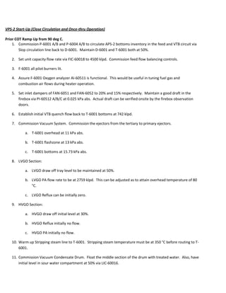
- 2. START-UP GUIDANCE VPS-2 t=0 t=10h Tag: Description D-6001 Level& Temp P-6001 Feed Pump Spill back 1000 KL.d-1 1000 2000 3000 4500 E-6001 / 2 Pre-heat 90 °C F-6001 Pressure and Nb of Burners kPA 10 16 FIC-5/7/11/12 Flow per pass KL.d-1 250 500 750 1100 TIC-60024 Coil Outlet Temp °C 90 200 320 350 407 FIC-4/7/9/14 Dilution steam t.h-1 0,2 per pass 0,5 per pass mini AT-60504 O2 / Air excess PT-60512 Draft kPA Fan-6052 FDF 13500 27000 50000 Fan-6051 IDF 40000 70000 P-6004 Quench LIC-60009 Bottom column 40 % TI-60036 Flash zone temp °C J-6003 ABC 82 mmHg 80°C 80°C 80°C J-6002 ABC 98 mmHg J-6001 ABC 118 mmHg <200°C <300°C <360°C LVGO Reflux 0 t/h 2-5t/h 5-10t/h 10-15t/h P-6005 LVGO Draw off level 70 % LVGO pump around 100 t/h HVGO Reflux Wash oil 1 t/h 4t/h 8 10 15 20 HVGO Draw off level 70 % P-6002 HVGO pump around 100 t/h 150°C 180°C Stripping steam LP D-6002 Level in Vacuum condensate drum 50% Amine absorber LP Steam MP steam Increase flow rate per pass up- to Cold circulation 250 0 90 Flow to Pre heat @90°C 60% Neutral same temp Shell side tube side 2 mini firing P=0,500 Start to inject a small flow of dilution steam when Inlet temperature = 250°C Conservative ramp-up to conduct hot circulation: Survey the temperaure in D-6001 max allowed 110-120°C Hot Circulation 230°C Hot circulation 1st stage ramp-up Initial conditions: 4 burner firing P< 0,500kPA Increasing COT set- point gradualy up to: Lit 2 addirtional burners (Ideal location to balance heat on each of 4 pass) t=3h 2nd stage ramp-up t=7h 6 burners firing P<0,500kPA 8 burners firing P<0,500kPA 3rd stage ramp-up 12 380 Balance flow per pass Ejector pulling vacuum J-6003 B + J-6002 A Check excess air during at each burner ignition and ajust combustion with 15% air excess O2 in Flus gas = 3% To be kept as a constant value. Field operator to check and report in case of positive pressure in the combustion chamber If level increase give preference to COT temp increase against total flow rate -0,250 Inlet Damper =15% 6800m3/h T(in) < 200°C Inlet damper 20% 10000m3/h 6-7%O2 / 30% Air excess J-6002 B + J-6001 A Stabilisation of flow to DCU feed tank at 50t/h To be set with controller in auto-mode to keep draft at bridgwall. Let inlet temp increase up to 200°c. Check load during ramp-up risk of overload due to low flue gas temperature Incrase gradualy paying attention to IDF and Nb of burners lit Establish a circulation loop @30t/h via by- pass of FV-600021. Ensure DCU tank have room enougth Set point TIC 60043@49°C Temp= 90°C Temp=90°C Start fan cooler E-6008 and start reflux at best time follow level of skimmed oil Low temp and maximise flowrate Keep temp as low as possible To be carefully follwed Start production of LVGO @ 150°C Set point of TIC @360°C. Controler in auto mode, closing by-pass valve gradualy with temp ramp-up J-6003 AFlash zone TOP Bottom Allmost all feed flow rate going to DCU feed tank Start steam generation and superheating Cool down the recirculation / Follow up temperature ramp up Increase gradualy will decrease due to wash oil Follow level of skimmed oil in D-6002 Vacumm seal drum Ready to go Sour gas to atm Skimed oil pump and Sour water pumps ready to go P-6006/7 Venting via UV-60009 & X-6003 Venting Check temp of LP steam If OK route to Column Start production of HVGO @ 290°C Venting venting Setting TIC-60043@49°C start fanof E-6008 Must operate continously if dry the operating temperature will Line-up stripping steam when bottom temperature is above 250 In operation if possible Steam generators ready, filled with boiled feed water P-6004 A&B E-6002 E-6001 P-6001 A&B D-6001 F-6001 P-6002 FIL-6002 FIL-6001 P-6005 E-6008C-6001 Quench LVGO HVGO E-6004 E-6003 LP & MP Steam generation
- 3. 12. Commission D-6007 and D-6008. a. Line out the LP and MP steam generation lines to atmosphere. b. Close UV-60010 to isolate LP steam line from F-6001 to the LPS header. Vent to atmosphere through superheated LP steam silencer X-6003 and saturated LP steam silencer X-6005. c. Close UV-60020 to isolate MP steam line from F-6001 to the MPS header. Vent to atmosphere through superheated MP steam silencer X-6002 and saturated MP steam silencer X-6004. d. Also line up LP and MP Steam Generators with Continuous Blowdown Drum D-6009 and Intermittent Blowdown Drum D-6010. e. Commission LIC-60142 and set to 50%. f. Commission CWS flow to E-6013 g. Fill up MP and LP steam generator drums D-6007 and D-6008 with Boiler Feed Water (BFW) and commission their respective level controllers LIC-60029 and LIC-60032 set to 50%. Close Hot Circulation from COT 90 °C to 300°C. 13. Maintain circulation of Feed/VTB circuits at 4500 klpd. 14. Ramp up furnace COT by commissioning main gas burners in staggered pattern. Max heat up rate is 50°C per hour. 15. Also, closely monitor recycle stream temperature back to D-6001. Must be maintained at 125 °C max. 16. Start to inject small amount of dilution steam when furnace CIT is already at 250 °C. 17. Closely monitor O2 content in the flue gases via AI-60511. Suggested flue gas O2 content is 3% vol, but this value can be changed depending on the appearance of the flue gases coming out from the stack. 18. Increase combustion air flow accordingly with the increase in main burner firing. This is also a good opportunity to put combustion air flow and fuel gas flows in automatic to verify if the cross limiting control is functioning well. We can revert back to manual mode once the control logic was verified unreliable. 19. Maintain VTB quench flow back to T-6001 at 742 klpd. Commission TIC-60030 T-6001 bottoms temperature controller set at 360 °C as necessary. 20. When LVGO pumparound stream temperature is already increasing, commissioned E-6008 to cool down LVGO PA to 50 °C set point. Note again that tower overhead temperature can be as high as 80°C max. 21. Gradually increase LVGO flowrate to approximately 138 klpd. Note again that tower overhead temperature can be as high as 80°C max. 22. During heat up, steam would be generated from D-6007 and D-6008. For the LP steam line, route LP steam generated to F-6001 superheating coils and vent thru X-6003. Commission PIC-60114 and set to 450
- 4. kPag. The LP steam can help in warming up the stripping steam line prior routing to T-6001. Cut in Stripping steam to T-6001 at 350°C stripping steam temperature. 23. At this stage, F-6001 firebox temperature TI-60513 A/B/C can already be as high as 610 to 620 °C. By then, we can route the washed sour gas from D-6004 overhead to F-6001 for burning. 24. At 300 °C COT, we expect LVGO and HVGO draw off trays to increase in level. By then, we can revert to once- thru operation. Expected slop stream temperature is 117°C max. Coordinate with OM&S if IFO tank can accommodate off spec products. Admit fresh feed from either APS-2 or TK-338 whichever is desirable. Once-thru Operation 25. After hitting COT of 300 °C, VPS-2 would be in once-thru operation. Continue COT ramp up, 50°C per hour max. Target COT is 411 °C. 26. As soon as VPS-2 is already in once thru mode, LVGO and HVGO PA and Reflux stream can then be fully commissioned. a. LVGO PA: 3285 klpd. b. LVGO Reflux : 414 klpd c. HVGO PA: 7531 klpd d. HVGO Reflux: 1360.77 klpd 27. Cold product stream temperatures are expected to be at: a. LVGO @ 50°C b. HVGO @ 80°C c. VTB @ 170°C 28. Commission Tempered water System. Commission E-6007 and set TIC-at 80°C. if slop stream is in need of further cooling as can be limited by the receiving tank, E-6007 operation can be maximized to facilitate further cooling. Same goes for LVGO cooler E-6008. 29. Allow VPS-2 to stabilize and obtain samples of product streams for testing. 30. As soon as product streams are on spec, we can then send products to D/S units or intermediate tanks.