
Recommended
More Related Content
What's hot
What's hot (20)
Similar to report on stereoithographty
Similar to report on stereoithographty (20)
Recently uploaded
Recently uploaded (20)
report on stereoithographty
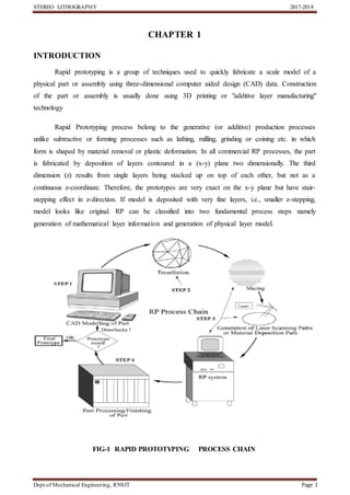
- 1. STEREO LITHOGRAPHY 2017-2018 Dept.of Mechanical Engineering, RNSIT Page 1 CHAPTER 1 INTRODUCTION Rapid prototyping is a group of techniques used to quickly fabricate a scale model of a physical part or assembly using three-dimensional computer aided design (CAD) data. Construction of the part or assembly is usually done using 3D printing or "additive layer manufacturing" technology Rapid Prototyping process belong to the generative (or additive) production processes unlike subtractive or forming processes such as lathing, milling, grinding or coining etc. in which form is shaped by material removal or plastic deformation. In all commercial RP processes, the part is fabricated by deposition of layers contoured in a (x-y) plane two dimensionally. The third dimension (z) results from single layers being stacked up on top of each other, but not as a continuous z-coordinate. Therefore, the prototypes are very exact on the x-y plane but have stair- stepping effect in z-direction. If model is deposited with very fine layers, i.e., smaller z-stepping, model looks like original. RP can be classified into two fundamental process steps namely generation of mathematical layer information and generation of physical layer model. FIG-1 RAPID PROTOTYPING PROCESS CHAIN
- 2. STEREO LITHOGRAPHY 2017-2018 Dept.of Mechanical Engineering, RNSIT Page 2 Although several rapid prototyping techniques exist, all employ the same basic five-step process. The steps are: 1. Create a CAD model of the design 2. Convert the CAD model to STL format 3. Slice the STL file into thin cross-sectional layers 4. Construct the model one layer atop another 5. Clean and Finish the model 1. CAD MODEL CREATION: First, the object to be built is modeled using a Computer Aided Design (CAD) software package. Solid modelers, such as Pro/ENGINEER, tend to represent 3-D objects more accurately than wire-frame modelers such as AutoCAD, and will therefore yield better results. The designer can use a pre-existing CAD file or may wish to create one expressly for prototyping purposes. This process is identical for all of the RP build techniques. 2. CONVERSION TO STL FORMAT: The various CAD packages use a number of different algorithms to represent solid objects. To establish consistency, the STL (stereo lithography, the first RP technique) format has been adopted as the standard of the rapid prototyping industry. The second step, therefore, is to convert the CAD file into STL format. This format represents a three-dimensional surface as an assembly of planar triangles, "like the facets of a cut jewel". The file contains the coordinates of the vertices and the direction of the outward normal of each triangle. Because STL files use planar elements, they cannot represent curved surfaces exactly. Increasing the number of triangles improves the approximation, but at the cost of bigger files size. Large, complicated files require more time to pre- process and build, so the designer must balance accuracy with manageability to produce a useful STL file. Since the STL format is universal, this process is identical for all of the RP build techniques. 3. SLICE THE STL FILE: In the third step, a pre-processing program prepares the STL file to be built. The standard data interface between CAD software and the machine is the STLformat (Stereolithography). An STL-file approximates the shape of a part using triangular facets. Small facets produce a high quality surface. Several programs are available, and most allow the user to adjust the size, location and orientation of the model. Build orientation is important for several reasons. First, properties of rapid prototypes vary from one coordinate direction to another. For example, prototypes are usually weaker and less accurate in the z (vertical) direction than in the x-y plane. In addition, part `
- 3. STEREO LITHOGRAPHY 2017-2018 Dept.of Mechanical Engineering, RNSIT Page 3 orientation partially determines the amount of time required to build the model. Placing the shortest dimension in the z direction reduces the number of layers, thereby shortening build time. The pre- processing software slices the STL model into a number of layers from 0.01 mm to 0.7 mm thick, depending on the build technique. The program may also generate an auxiliary structure to support the model during the build. Supports are useful for delicate features such as overhangs, internal cavities, and thin-walled sections. Each RP machine manufacturer supplies their own proprietary pre-processing software FIG-2 GENERAL METHODS EMPLOYED FOR RAPID PROTOTYPING 4.LAYER BY LAYER CONSTRUCTION: The fourth step is the actual construction of the part. Using one of several techniques (described in the next section) RP machines build one layer at a time from polymers, paper, or powdered metal. Most machines are fairly autonomous, needing little human intervention. 5. CLEAN AND FINISH: The final step is post-processing. This involves removing the prototype from the machine and detaching any supports. Some photosensitive materials need to be fully cured before use. Prototypes may also require minor cleaning and surface treatment. At this stage, generally some manual operations are necessary therefore skilled operator is required. In cleaning, excess elements adhered with the part or support structures are removed. Sometimes the surface of the model is finished by sanding, polishing or painting for better surface finish or aesthetic appearance and durability. Prototype is then tested or verified and suggested engineering changes are once again incorporated during the solid modelling stage.
- 4. STEREO LITHOGRAPHY 2017-2018 Dept.of Mechanical Engineering, RNSIT Page 4 FIG-3 GENERALIZED ILLUSTRATION OF DATA FLOW IN RP The different techniques of rapid prototyping are- 1. 3D printing (3DP) 2. Ballistic particle manufacturing (BPM) 3. Directed light fabrication (DLF) 4. Direct-shell production casting (DSPC) 5. Fused deposition modelling (FDM) 6. Laminated object manufacturing (LOM) 7. Shape deposition manufacturing (SDM) (and Mold SDM) 8. Solid ground curing (SGC) 9. Selective laser sintering (SLS) 10. Stereo lithography(SLA)
- 5. STEREO LITHOGRAPHY 2017-2018 Dept.of Mechanical Engineering, RNSIT Page 5 CHAPTER 2 STEREO LITHOGRAPHY (SLA) Stereo lithography (SLA or SL; also known as stereo lithography apparatus, optical fabrication, photo-solidification, or resin printing) is a form of 3-D printing technology used for creating models, prototypes, patterns, and production parts in a layer by layer fashion using photo polymerization, a process by which light causes chains of molecules to link, forming polymers. Those polymers then make up the body of a three-dimensional solid. Research in the area had been conducted during the 1970s, but the term was coined by Chuck Hull in 1984 when he applied for a patent on the process, which was granted in 1986. Stereo lithography can be used to create things such as prototypes for products still in early design, medical models and computer hardware as well as many other applications. While stereo lithography is fast and can produce almost any design, it can be expensive. FIG-4 STEREO LITHOGRAPHY PROCESS `
- 6. STEREO LITHOGRAPHY 2017-2018 Dept.of Mechanical Engineering, RNSIT Page 6 ````````````````````````````````````````````````` CHAPTER 3 WORKING Stereo lithography is an additive manufacturing process that works by focusing an ultraviolet (UV) laser on to a vat of photopolymer resin. With the help of computer aided manufacturing or computer aided design (CAM/CAD) software, the UV laser is used to draw a pre- programmed design or shape on to the surface of the photopolymer vat. Photopolymers are sensitive to ultraviolet light, so the resin is photo chemically solidified and forms a single layer of the desired 3D object. Then, the build platform lowers one layer and a blade recoats the top of the tank with resin. This process is repeated for each layer of the design until the 3D object is complete. Completed parts must be washed with a solvent to clean wet resin off their surfaces. It is also possible to print objects "bottom up" by using a vat with a transparent bottom and focusing the UV or deep-blue polymerization laser upward through the bottom of the vat. An inverted stereo lithography machine starts a print by lowering the build platform to touch the bottom of the resin-filled vat, then moving upward the height of one layer. The UV laser then writes the bottom-most layer of the desired part through the transparent vat bottom. Then the vat is "rocked", flexing and peeling the bottom of the vat away from the hardened photopolymer; the hardened material detaches from the bottom of the vat and stays attached to the rising build platform, and new liquid photopolymer flows in from the edges of the partially built part. The UV laser then writes the second-from-bottom layer and repeats the process. An advantage of this bottom-up mode is that the build volume can be much bigger than the vat itself, and only enough photopolymer is needed to keep the bottom of the build vat continuously full of photopolymer. This approach is typical of desktop SLA printers, while the right-side- up approach is more common in industrial systems. Stereo lithography requires the use of supporting structures which attach to the elevator platform to prevent deflection due to gravity, resist lateral pressure from the resin-filled blade, or retain newly created sections during the "vat rocking" of bottom up printing. Supports are typically created automatically during the preparation of CAD models and can also be made manually. In either situation, the supports must be removed manually after printing.
- 7. STEREO LITHOGRAPHY 2017-2018 Dept.of Mechanical Engineering, RNSIT Page 7 FIG-5 COMPONENTS OF STEREO LITHOGRAPHY PROCESS
- 8. STEREO LITHOGRAPHY 2017-2018 Dept.of Mechanical Engineering, RNSIT Page 8 STEREO LITHOGRAPHY- POINT BY POINT SCANNING FIG-6 SLA POINT SCANNING Laser traces current cross section on to the surfaces of photo curable liquid acrylate resin Polymer solidifies when struck by the lasers intense UV light Elevator lowers hardened cross section below the liquid surface Laser prints the next cross section directly on top of previous After entire 3D part is formed it is photo cured
- 9. STEREO LITHOGRAPHY 2017-2018 Dept.of Mechanical Engineering, RNSIT Page 9 STEREOLITHOGRAPHY-LAYER AT A TIME FIG-7 SLA LAYER VIEW Cross section shape is printed on to a glass mark Glass mark is positioned above photo polymer tank UV lamp shines through mask on to photo polymer New coat of photo polymer is applied 12-15 minute post cure is required PRODUCT PRINTEDUSING STEREOLITHOGRAPHY FIG-8 SLA PRODUCT
- 10. STEREO LITHOGRAPHY 2017-2018 Dept.of Mechanical Engineering, RNSIT Page 10 CHAPTER 4 PHOTOPOLYMERS There are many types of liquid photopolymers that can be solidified by exposure to electromagnetic radiation, including wavelengths in the gamma rays, X-rays, UV and visible range, or electron-beam (EB). The vast majority of photopolymers used in the commercial RP systems, including 3D Systems’ SLA machines are curable in the UV range. UV-curable photopolymers are resins which are formulated from photoinitiators and reactive liquid monomers. There are a large variety of them and some may contain fillers and other chemical modifiers to meet specified chemical and mechanical requirements. The process through which photopolymers are cured is referred to as the photopolymerization process The resins used for the SLA process are composed of two basic parts. The first is a photoinitiator which absorbs laser energy to start a chemical reaction which begins the polymerization process. The second part is a polymer which hardens after reacting with the photoinitiator. Certain polymers also contain thermoset materials which allow the finished part to harden with the introduction of heat. These resins are usually either epoxy based (which tends to be stronger but also more expensive) or acrylate-based. There have also been recent developments which incorporate ceramics into the epoxy resin, making it far stronger, and much more useful for various tests. The most commonly used resins are SOMOS series SLA Somos 7120 - A high speed general use resin that is heat and humidty resistant. SLA Somos 9120 - A robust accurate resin for functional parts. For more information on this material please read the material SLA Somos 9920 - A durable resin whose proper Gas mimic polypropylene. Offers superior chemical resistance, fatigue proper Gas, and strong memory retention. SLA Somos 10120- Water Clear - A general purpose resin with mid-range mechanical proper Gas. Transparent parts are possible if finished properly.
- 11. STEREO LITHOGRAPHY 2017-2018 Dept.of Mechanical Engineering, RNSIT Page 11 SLA Somos 11120 Watershed -Produces strong, tough, water-resistant parts. Many of its mechanical proper Gas mimic that of ABS plastic. SLA Somos 14120 White - A low viscosity liquid photopolymer that produces strong, tough, water-resistant parts. SLA Somos Proto Tool – Proto Tool is a high density material that transcends currently available stereo lithography resins by offering superior modulus and temperature resistance TABLE-1 SOMOS SERIES .
- 12. STEREO LITHOGRAPHY 2017-2018 Dept.of Mechanical Engineering, RNSIT Page 12 CHAPTER 5 PROCESSPARAMETERS TABLE-2 SLA PARAMETERS LASER TYPE Helium –CADMIUM (He-Cd) LASER POWER 24 KW SLICE THICKNESS RANGE 0.1-0.4mm SCAN SPEED 0.5-1.5m/s MAXIMUM PART VOLUME 0.25*0.25*0.25 m` MAXIMUM PART WEIGHT 9 Kgs LASER LIFE 2000 Hrs RECOAT MATERIAL ZAPHIR BEAM DIAMETER 0.2mm FIG-9 STEREO LITHOGRAPHY 3D VIEW `````````````````````
- 13. STEREO LITHOGRAPHY 2017-2018 Dept.of Mechanical Engineering, RNSIT Page 13 CHAPTER 6 BENEFITS High precision, fine detail: due to the great thinness of each layer applied in stereo lithography (0.05 to 0.10 mm) and the fine laser beam, it is possible to obtain prototypes with a very realistic finish and complex geometric shapes. Quality of the part: despite the use of substitution materials (resin), parts made with stereo lithography have good functional surface quality. Smooth finish: In stereolithography the resulting parts have a smooth finish with the option to choose between a number of resins for different renderings. From the smallest to the largest:with stereolithography, it is possible to create small parts with high definition, as well as larger parts up to two metres in size, while maintaining high precision. Price and deadlines: By choosing the stereo lithography method, you can obtain a part in about two days, because the 3D files are sufficient to launch a printing. On the other hand, the cost is reasonable, because it is not necessary to create a mould, as stereolithography works by adding material. Customized colouring Multi-part assemblies are possible
- 14. STEREO LITHOGRAPHY 2017-2018 Dept.of Mechanical Engineering, RNSIT Page 14 CHAPTER 7 DISADVANTAGES Fragility: stereo lithography uses equivalent materials which are resins. The parts thus obtained are more fragile than the final parts. If the quality of the finish allows functional prototypes to be obtained, stereo lithography does not, however, allow parts that can be used for mechanical testing to be obtained. Expensive machines: if we had predicted the boom in 3D printing in the past few years, experts have neglected the cost of the machines and the difficulty of their operation. Thus, it is more difficult for companies to create their own prototypes in stereo lithography, so they often prefer to rely on specialised companies. Unit production: due to the time required to produce a part, the use of stereolithography is limited to three copies,so does not make sense for production. Depending on the material, components may be brittle. Support structures can limit design freedom Components are only UV-resistant to a limited extent.
- 15. STEREO LITHOGRAPHY 2017-2018 Dept.of Mechanical Engineering, RNSIT Page 15 CHAPTER 8 APPLICATIONS 1. POWDER INJECTIONMOLDING(PIM) PIM technology is a combination of powder metallurgy with injection molding of thermoplastics. As a result it is possible to manufacture complex parts with metals, ceramics & composites. The hard particles of ceramics or metals are mixed with a binder system that covers the particles. This binder system is made usually of thermoplastic, wax and additives that allow the mixture to be molten and injected inside a mold in a way similar to that performed for thermoplastics alone. A basic sequence of the powder injection molding process is presented in Fig. FIG-10 SLA MOLDING 2. COMPLEXSPINE SURGERY It is also possible to determine the standardization of surgical techniques, when accompanied by special procedures. In the case of surgery for placement of prostheses the stereo lithographic model has been used to determine ideal dimensions of the material to be implanted. Of all the techniques the stereo lithography is the most used, presenting application in the aero-space industry for more than two decades. The adaptation for medical appliance with the substitution of graphic drawings for radiological exams can be done without the loss of precision, maintaining a level with variation of 1mm in the graphic interface. The limitation for regular use of this technique is the high cost involved in prototyping process (the important support to complex procedures)
- 16. STEREO LITHOGRAPHY 2017-2018 Dept.of Mechanical Engineering, RNSIT Page 16 FIG-11 SLA 3D MEDICAL MODELS 3. 3-D PRINTING IN SPACE The establishment of a manned human colony on the Moon (or on Mars) needs infrastructures to shelter astronauts and scientific instrumentation from very harsh environments, characterised by deep vacuum conditions, strong temperature fluctuations, micrometeoroids and solar radiation. Among the possible options for building a Moon Base - digging the lunar surface in order to build an underground habitat; bringing fully functional and complete habitation modules from Earth to be mounted on the Lunar surface; or directly building on the Moon surface using local material - 3D printing offers the most effective alternative as addressed in recent ESA research activities. Resources already available on the surface (the lunar regolith) can be used as a building material and a solar powered 3D printer can focus endlessly available sunlight to sinter successive layers of regolith into structural elements of the habitat structure. This option offers tremendous logistical, technical, economical and safety advantages as opposed to launching building materials and tools from Earth. It could also decouple the launch timeline of astronauts with respect to the manufacturing of the Moon habitat, which can start much earlier in a completely automated and safe manner before arrival of the first crew.
- 17. STEREO LITHOGRAPHY 2017-2018 Dept.of Mechanical Engineering, RNSIT Page 17 FIG-12 SLA IN SPACE 4. AUTOMOBILE INDUSTRY In 2014, Local Motors debuted Strati, a functioning vehicle that was entirely 3D Printed using ABS plastic and carbon fiber, except the powertrain. In 2015, the company produced another iteration known as the LM3D Swim that was 80 percent 3D-printed In 2016, the company has used 3D printing in the creation of automotive parts, such ones used in Olli, a self-driving vehicle developed by the company. In May 2015 Airbus announced that its new Airbus A350 XWB included over 1000 components manufactured by 3D printing.3D printing is also being utilized by air forces to print spare parts for planes. In 2015, a Royal Air Force Eurofighter Typhoon fighter jet flew with printed parts. The United States Air Force has begun to work with 3D printers, and the Israeli Air Force has also purchased a 3D printer to print spare parts.
- 18. STEREO LITHOGRAPHY 2017-2018 Dept.of Mechanical Engineering, RNSIT Page 18 FIG-13 3D PRINTED CAR MODEL
- 19. STEREO LITHOGRAPHY 2017-2018 Dept.of Mechanical Engineering, RNSIT Page 19 5. SOCIOCULTURAL In 2005, academic journals began to report on the possible artistic applications of 3D printing technology, being used by artists such as Martin John Callanan at The Bartlett school of architecture. By 2007 the mass media followed with an article in the Wall Street Journal and Time Magazine, listing a printed design among their 100 most influential designs of the year. During the 2011 London Design Festival, an installation, curated by Murray Moss and focused on 3D Printing, was held in the Victoria and Albert Museum (the V&A). The installation was called Industrial Revolution 2.0: How the Material World will Newly Materialize. At the 3D Printshow in London, which took place in November 2013 and 2014, the art sections had works made with 3D printed plastic and metal. Several artists such as Joshua Harker, Davide Prete, Sophie Kahn, Helena Lukasova, Foteini Setaki showed how 3D printing can modify aesthetic and art processes. In 2015, engineers and designers at MIT's Mediated Matter Group and Glass Lab created an additive 3D printer that prints with glass, called G3DP. The results can be structural as well as artistic. Transparent glass vessels printed on it are part of some museum collections. The use of 3D scanning technologies allows the replication of real objects without the use of moulding techniques that in many cases can be more expensive, more difficult, or too invasive to be performed, particularly for precious artwork or delicate cultural heritage artifacts where direct contact with the moulding substances could harm the original object's surface. FIG-14 3D PRINTED JEWELERY
- 20. STEREO LITHOGRAPHY 2017-2018 Dept.of Mechanical Engineering, RNSIT Page 20 CHAPTER 9 CONCLUSIONS • Stereo lithography is fast and effective. • Stereo lithography can be applied to almost every industry, including oil refining, petrochemical, power and marine. • Stereo lithography saves time, money and allows speed delivery.
- 21. STEREO LITHOGRAPHY 2017-2018 Dept.of Mechanical Engineering, RNSIT Page 21 CHAPTER 10 REFERENCES [1] Base paper : stereo lithography : speeding time to market, Diana Kalisz, IEEE. [2] Rapid prototyping, Terry Wohler's report 2000, Wohler's association 2000. [3] Jacobs, Paul F. “Introduction to Rapid Prototyping and Manufacturing.” Rapid Prototyping and Manufacturing: Fundamentals of Stereo lithography. 1st Ed. (1992). [4] Crivello, James V., and Elsa Reichmanis. "Photopolymer Materials and Processes for Advanced Technologies." Chemistry of Materials Chem. Mater.