1. 6/2/2022
1
STEEL STRUCTURES
BUILDING CONNECTIONS
Dr Sarmad Shakeel
sshakil@nice.nust.edu.pk
1
TYPE OF CONNECTIONS
2
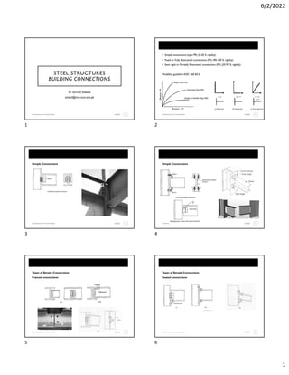
• Simple connections (type PR) (0-20 % rigidity)
• Fixed or Fully Restrained connections (FR) (90-100 % rigidity)
• Semi rigid or Partially Restrained connections (PR) (20-90 % rigidity)
Modelling guideline ASIC 360 B3.6
TYPE OF CONNECTIONS
3
Simple Connections
TYPE OF CONNECTIONS
4
Simple Connections
TYPE OF CONNECTIONS
5
Types of Simple Connections
Framed connections
TYPE OF CONNECTIONS
6
Types of Simple Connections
Seated connections
1 2
3 4
5 6
2. 6/2/2022
2
TYPE OF CONNECTIONS
7
PR Connections
TYPE OF CONNECTIONS
8
PR Connections
TYPE OF CONNECTIONS
9
FR Connections
TYPE OF CONNECTIONS
10
FR Connections
AISC MANUAL STANDARD CONNECTION TABLES
11
Tables for selecting standard connections
• Bolted or welded two angle framed connections
• Seated beam connections
• Stiffened seated beam connections
• Eccentrically loaded connections
• Single angle frame connection
• Others
Convention used in the tables
AISC MANUAL STANDARD CONNECTION TABLES
12
Upper part ofTables give the bolt and angle available strength of connection based
on following parameter
As you move down the table, the strength
starts to reduce as well as the number of rows.
All Bolted simple connections
7 8
9 10
11 12
3. 6/2/2022
3
AISC MANUAL STANDARD CONNECTION TABLES
13
Lower part ofTables give the beam web available strength of connection based on
following parameter
EXAMPLE
14
EXAMPLE
15
Start by looking at least number of rows that can be used with W30.
Not good enough move to 6 rows
EXAMPLE
16
Thickness of angle 5/16, in length of angle 15+2(1 1/4)=17.5 in < 26.5 in (T of 30 x 108)
EXAMPLE
17
EXAMPLE
18
Min. edge distance for ¾ bolt is 1 inch –AISC 360Table J3.4
Length of legs
Reqd Gage of legs bolted to web= 1 3/8 (H2) +3/4 (C2) +5/16 (L thickness)= 2.4375 (2.5 in is
used)
Reqd Gage of legs bolted to column=1¼+1 3/8+5/16 =2 15/16 =3 in (approx.)
Length of leg bolted to web of beam = 2.5 +1 =3.5 in
Length of leg bolted to columns= 3+1 =4 in
Use 2 Ls 4 x 3 ½ x 5/16 x 1 ft-5 ½ in A36
13 14
15 16
17 18
4. 6/2/2022
4
AISC MANUAL STANDARD CONNECTION TABLES
19
• Weld A- weld used to connect angles to beam web
• Weld B- Weld used at all other locations
• Based on instantons centre of rotation method
• Angle thickness is 1/16+ weld size or min value for bolt in Table 1
• Table is only for E70 electrodes
Shop welded and site bolted simple connections
EXAMPLE
20
EXAMPLE
21
• Depth of weld is ok It is less thanT of beam web (26.5 in)
• Min. angle thickness for 3/16 weld is ¼ in as J2.2 b
• The minimum web thickness 0.286 in is less than 0.47 in (actual)
EXAMPLE
22
• For 20 ½ angle length 7 row bolted connection is suitable fromTable 10-1
• For ¼ in angle thickness, strength is not sufficient, use 5/16 thickness
AISC MANUAL STANDARD CONNECTION TABLES
23
All welded simple connections
AISC MANUAL STANDARD CONNECTION TABLES
24
Single plate or shear tab framing simple connections
19 20
21 22
23 24
5. 6/2/2022
5
AISC MANUAL STANDARD CONNECTION TABLES
25
Single plate or shear tab framing simple connections
AISC MANUAL STANDARD CONNECTION TABLES
26
Single plate or shear tab framing simple connections
• Tabulated bolt and plate available strengths consider the
limit states of bolt shear, bolt bearing on the plate, shear
yielding of the plate, shear rupture of the plate, block shear
rupture of the plate, and weld shear.
• Values are tabulated for two through twelve rows of 3/4-in.-,
7/8-in.-, 1-in.- and 11/8-in.-diameter Group A and Group B
bolts at 3-in. spacing.
• For calculation purposes, plate edge distance, Lev, is in
accordance with AISC Specification Section J3.10 and Table
J3.4. End distance, Leh, is provided as 2 times the diameter of
the bolt, to match tested connections.
• Weld sizes are tabulated equal to (5/8)tp.
EXAMPLE
27
EXAMPLE
28
EXAMPLE
29
Page 10-106 AISC Manual
EXAMPLE
30
25 26
27 28
29 30
6. 6/2/2022
6
EXAMPLE
31
106
AISC MANUAL STANDARD CONNECTION TABLES
32
End plate shear connection
• Plate end welded to the beam while it is bolted on site to column.
• Design is explained in part 12 of the manual
AISC MANUAL STANDARD CONNECTION TABLES
33
Welded seated beam connections
• While the seat angle is assumed to carry the entire end reaction of the supported beam,
• the top angle must be placed as shown or in the optional side location for satisfactory
• performance and stability.
• The top angle and its connections are not usually sized for any calculated strength
requirement.
• Tabulated seat available strengths consider the limit states of shear yielding and flexural
• yielding of the outstanding angle leg.
AISC MANUAL STANDARD CONNECTION TABLES
34
Welded/Bolted seated beam connections
AISC MANUAL STANDARD CONNECTION TABLES
35
Welded/Bolted seated beam connections
AISC MANUAL STANDARD CONNECTION TABLES
36
Moment resisting FR connections
31 32
33 34
35 36
7. 6/2/2022
7
EXAMPLE
37
EXAMPLE
38
EXAMPLE
39
AISC MANUAL STANDARD CONNECTION TABLES
40
Moment resisting FR connections
Use of cover plates
AISC MANUAL STANDARD CONNECTION TABLES
41
Column web stiffeners
• To resist forces from the connection
• A thick flange column can also be used because column web stiffener plates are
quite expensive and nuisance to use
• Length of stiffener plates
AISC MANUAL STANDARD CONNECTION TABLES
42
Column web stiffeners
Stiffener requirements for concentrated forces ASIC 360 J10.8
37 38
39 40
41 42
9. 6/2/2022
9
EXAMPLE
49
AISC MANUAL STANDARD CONNECTION TABLES
50
Moment resisting column base plate connection
• Small Moment- Complete base plate in compression- Anchor bolt theoretically
not required- But provided for column alignment and resisting accidental forces.
• Large Moment- Part of it might go in tension
• Base plates could be welded in shop- may required level plates.
• Could be welded on site after proper levelling
• Anchor bolts are embedded sufficiently into the foundation to develop anchor
bolt forces. (Embedment strength based on RC design)
AISC MANUAL STANDARD CONNECTION TABLES
51
Moment resisting column base plate connection
LRFD design Process (ASD is similar with only difference in partial safety factors
EXAMPLE
52
EXAMPLE
53
EXAMPLE
54
49 50
51 52
53 54