
Recommended
More Related Content
What's hot
What's hot (20)
Similar to Dobilla bailey bridge sections
Similar to Dobilla bailey bridge sections (20)
Recently uploaded
Recently uploaded (20)
Dobilla bailey bridge sections
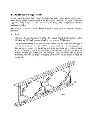
- 1. 1 Dobilla Bailey Bridge sections For the construction of the bailey bridge the standardized bailey bridge sections has been used. Those section cannot be manufactured in the local market. The U.S. M2 Bailey components supplied by Bailey Bridges, Inc. The components of the Bailey Bridge are highlighted with their specifications below. The Bailey M2 bridge set contains 29 different items of bridge parts and 30 items of erection equipment. 1.1 Panel The panel is the basic member of the bridge. It is a welded and high tensile steel truss section 10 ft long and 5ft. 1 inch high and 6.5 inches wide. It weighs 262 kilograms. The horizontal members of the panel are called chords. Both the chords have male lugs at one end and female lugs at another end. The panels are joined end by end by engaging these lugs and placing the panel pins through the holes in the lugs. On the top of the bottom chord are the four seating or dowels. The beams that for a retainer clip. A groove is cut across the head of the panel pin retainer hole. The panel pins should be inserted with the groove horizontal; other-wise the flanges of the panel chord channel make it difficult to insert the retainer clip.
- 2. Short panel pin The short panel pin is 3/4 inch (1.9 centimeters) shorter than the normal panel pin and weighs 5.8 pounds (2.6 kilograms). It is used to pin the end posts of the outer and middle trusses in a triple- truss bridge.
- 3. 1.2 Transom The transom is a steel beam that supports the floor system of the bridge. It is 10 inches (25.4 centimeters) by 19 feet 11 inches (6.1 meters) long. It has a 4 1/2- inch (11.4 centimeters) flange and a 5/16-inch. The transom is a steel beam that supports the floor system of the bridge. It is 10 inches (25.4 centimeters) by 19 feet 11 inches (6.1 meters) long. It has a 4 1/2-inch (11.4 centimeters) flange and a 5/16-inch. The underside of the transom has six holes into which the panel dowels fit. The transom rests on the lower chord of the panel and is held in place with a transom clamp. The upper side of the transom has six lugs with an additional lug near each end. The stringers and rakers attach to these lugs. Transoms are normally spaced 5 feet (1.5meters) apart, one at the middle and one at the end of each panel, to support vehicles of class 70 or less. Four transoms per bay—two in the middle and one at each end of the panel—are required to support vehicles over class 70.
- 4. 1.3 Transom Clamp The transom clamp is a hinged screw-in type clamp, 13 1/2 inches (34.3 centimeters) high and 8 inches (20.3 centimeters) across the top. It weighs 7 pounds (3.2 kilograms). It clamps the transom to the vertical and bottom chord of the panel. It is tightened by a vise-handled screw. 1.4 Sway Brace The sway brace is a 1 1/8-inch (2.9 centimeters) steel rod, hinged at the center, and adjusted by a turnbuckle. It weighs 68 pounds (30.8 kilograms). At each end is an eye, and a chain with a pin attached. This pin is inserted through the eye to the sway brace to the panel. The sway brace is given the proper tension by inserting the tail of an erection wrench in the turnbuckle and screwing it tight. The locknut is then screwed up against the turnbuckle. Two sway braces are required in the lower chord of each bay of the bridge, except the first bay of the launching nose, and in each bay of overhead bracing.
- 5. 1.5 Bracing Frame The bracing frame is a rectangular frame, 4 feet 3 inches (1.3 meters) by 1 foot 8 inches (50.8 centimeters) with a hollow conical dowel in each comer. It weighs 44 pounds (20.0 kilograms). The bracing frame is used to brace the inner two trusses on each side of the double- and triple- truss bridge. Bracing bolts attach the bracing frames horizontally to the top chords of the bridge and vertically on one end of each panel in the second and third stories.
- 6. 1.6 Tie Plate A tie plate is a piece of flat steel 2 1/2 by 3/8 by 12 inches (6.4 by 1.0 by 30.5 centimeters) weighing 3 1/2 pounds (1.6kilograms). It has a hollow conical dowel at each end. The tie plate is used only in triple truss bridges. It secures the second truss to the third truss using the unoccupied raker holes in the panels at each joint and at the ends of the bridge. 1.7 Bracing Bolt A bracing bolt is 3/4 inch (1.9 centimeters) in diameter, 3 1/2 inches (8.9 centimeters) long, and weighs about 1 pound (0.5 kilograms). A special lug on its head prevents rotation when the bolt is tightened. A l 1/8inch (2.9 centimeters) wrench is used to tighten it. The bracing bolt is used to attach rakers, bracing frames, and tie plates to panels. It is inserted into the hollow dowels of the braces to draw parts into proper alignment. 1.8 Chord Bolt A chord bolt is 1 3/4 inches (4.4 centimeters) in diameter, 10 1/2 inches (26.7 centimeters) long, and weighs 7 1/2 pounds (3.4 kilograms). It is tapered through half its length to assist in drawing the panels into alignment. A 1 7/8-inch (4.8 centimeters) wrench is used to tighten the bolt. Chord bolts join the panels, one above the other, to form double and triple-story bridges. Two bolts per panel pass upward through holes in
- 7. the panel chords and are tightened with nuts on the lower chord of the upper story. They are also used to fasten overhead bracing supports to the top panel chord. 1.9 Stringers Stringers carry the bridge’s roadway. Each stringer consists of three 4- inches (10.2 centimeters) steel beams, 10 feet (3.0 meters) long, joined by welded braces. There are two types of stringers: plain stringers weighing 260 pounds (118 kilograms) and button stringers weighing 267 pounds (122 kilograms). They are identical except that the latter has 12 buttons which hold the ends of the chess (roadway) in place. Each bay of the bridge has six stringers: four plain stringers in the middle, and a button stringer on each side. The stringers are positioned by the lugs on the top of the transoms.
- 8. 1.10 Chess Chess often referred to as deck or decking, form the road surface. A piece of chess is 2 inches (5.1 centimeters) by 8 3/4 inches (22.2 centimeters) by 13 feet 10 inches (4.2 meters). It is made of wood and weighs 65 pounds (29.5 kilograms). It is notched at the ends to fit between the buttons of the bottom stringer. Each bay of the bridge contains 13 chess, which lie across the stringers and are held in place by the buttons. Chess are held down by ribbands. 1.11 Steel Ribband A ribband is a metal curb 8 inches (20.3 centimeters) high and 10 feet (3.0 meters) long. It weighs 162 pounds (73.5 kilograms). It is fastened to the button stringers by four J-type ribband bolts. 1.12 Ribband Bolt A ribband bolt is a J-type bolt, 1 inch (2.5 centimeters) in diameter and 8 5/8 inches (21.9 centimeters) long. It weighs 4 ½ pounds (2.0 kilograms). A 1 1/2-inch (3.8 centimeters) wrench is used to tighten it. The ribband bolt fastens the ribband to the button stringers and ramps. The hook end of the bolt grips the lower flange of the outer beam of the button stringer or ramp.
- 9. 1.13 End Post End posts are used on both ends of each truss of the bridge to take the vertical shear. They are placed only on the story carrying the decking. They are 5- foot 8-inch (1.7 meters) columns made of two 4-inch (10.1 centimeters) channels and plates welded together. There are two types; male and female, having male and female lugs, respectively. These lugs are secured to the end panels of the bridge by panel pins placed through holes in the lugs. The male and female end posts weigh 121 and 130 pounds (54.9 and 59.0 kilograms), respectively. End posts have a step to support a transom outside the panel at one end of the bridge. In jacking the bridge, the jack is placed under the step. The lower end of the end post has a bearing block with a semicircular groove which fits over the bearing.
- 10. 1.14 Bearing The bearing spreads the load of the bridge to the base plate. A bearing is a welded steel assembly containing a round bar which, when the bridge is completed, supports the bearing blocks of the end posts. During assembly of the bridge, it supports the bearing block of the rocking roller (explained later in this chapter). The bar is divided into three parts by two intermediate sections that act as stiffeners. The bearing is 4 5/16 inches (11.9 centimeters)
- 11. high and weighs 68 pounds (30.8 kilograms). One bearing is used at each corner of a single truss bridge and two bearings per corner for a double- or triple-truss bridge. 1.15 Base Plate The base plate is a welded steel assembly with built-up sides and lifting-hook eyes on the top at each corner. It is used under the bearings to spread the load from the bearings over the ground or grillage. The bottom surface of the baseplate is 13 1/2 square feet (1.25 meters 2). The base plate weighs 381 pounds (173 kilograms) and is large enough for the bearings at one corner of a single-, double-, or triple-truss bridge. Bearings can slide 9 inches (22.9 centimeters) longitudinally on the baseplate. The numbers 1,2, and 3 are embossed on the edges of the base plate to indicate the position of the plate under the inner truss of single-, double-, and triple-truss bridges respectively.
- 12. 1.16 Ramp Pedestal Ramp pedestals are built-up welded steel assemblies weighing 93 pounds (42.2 kilograms). They prevent the transoms supporting multiple-length ramps from over turning and spread the transom load over the ground. They are held in place by spikes or pickets driven through holes in their base plates. 1.17 Foot walk The foot walk may be of wood or aluminum. The wood foot walks are 2 feet 6 inches (0.8 meter) wide and 10 feet (3.0meters) long. The aluminum foot walks are 25 3/4 inches (65.4 centimeters) wide and 9 feet11 1/2 inches (3.0 meters) long. Supported on foot walk bearers, foot walks are laid along the outer sides of the bridge for use by foot troops.
- 13. 1.18 foot walk Bearer A foot walk bearer is a built-up beam of pressed steel 4 feet (1.2 meters) long, weighing 23 pounds (10.4 kilo grams). Bearers are attached to all transoms and hold the foot walk post. 1.19 Foot Walk post A foot walk post) is 4 feet (1.2 meters) high, weighs 10 pounds (4.5 kilograms), and is fitted into every foot walk bearer. Hand ropes are threaded through two eyes on each post and secured either to holdfasts on the banks or end foot walk posts. 1.20 Overhead bracing Support The overhead-bracing support is used to clamp overhead transoms and sway braces to trusses for overhead bracing of triple-story bridges. The support is a welded metal assembly that weighs 150 pounds (68.0 kilograms). It is fastened to the tops of third story panels by chord bolts. A transom is seated over the pintles on top of the support and secured by cleats over the lower flange held by four nuts and bolts. One support per girder is placed on each bay of bridge.