2. the case of multicarrier amplifiers,
depending on how capable the soft-
ware algorithms are in reducing the
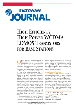
crest factor. Figure 1 shows the con-
tinuous wave power capability of a
100 W WCDMA (UMTS) LDMOS
transistor1 that uses the current tech-
nology. Power gain and drain efficien-
cy are shown.
At Pout = 100 W the power gain
compression is 1 dB. Theoretically,
considering a PAR of about 6 dB, and
in order to avoid significant distortion
under WCDMA signal conditions,
the device can be operated at a pow-
er level of approximately 25 W.
Where the device efficiency is 50
percent at 100 W, at 6 dB back-off, it
is about 26 percent. For previous
generations of LDMOS the efficiency
would be around 18 percent. Even
with a higher PAR, the device is still
able to meet the linearity require-
ments and maintain good drain effi-
ciency.
Typical linearity requirements un-
der a two-carrier WCDMA signal
(PAR = 8.5 dB at 0.01 percent proba-
bility of the cumulative distribution
function (CDF), that is the chance
that a peak 8.5 dB above the average
output power will occur) are –40 dBc
for the adjacent channel and –37 dBc
for the intermodulation distortion
(IMD) product generated by the two
carriers. Figure 2 shows the two-car-
rier WCDMA performance for the
same transistor.1 The linearity re-
quirements are met at an RF output
power of 43.6 dBm (approximately 23
W). Obviously the relationship be-
tween the average output power and
PAR does not hold up for the full 100
percent, since 43.6 dBm plus a PAR
of 8.5 dB adds up to 52.1 dBm, which
is well beyond the P1dB capability of
the device.
The other parameter that is im-
portant in order to meet a particular
linearity, in conjunction with the
probability on the CDF of the pre-
sented input signal, is the peak power
capability of the LDMOS transistor.
Appendix A presents the peak power
capability of the featured LDMOS
transistor, where a pulsed continuous
wave signal is used with a small duty
cycle (about 0.8
percent) to measure
the peak power.
It could be ar-
gued that it would
make more sense to
choose the duty cy-
cle such that the av-
erage power under
pulsed conditions
would be more rep-
resentative of the
actual average
WCDMA power,
which would actually lower the re-
ported peak power capability. It can-
not be said that there is a 100 percent
correlation between peak power ca-
pability of a transistor and achievable
linearity. The fact is, though, that a
higher peak power capability will re-
duce the amount of clipping of sig-
nals with high peak-to-average ratios,
and thus create a transistor that will
better fit in a base station amplifier
system environment.
AMPLIFIER EFFICIENCY
Having identified the important RF
parameters of a UMTS LDMOS base
station amplifier, the overall benefit of
better LDMOS technology can be de-
termined. Figure 3 shows a block dia-
gram of a UMTS amplifier arrange-
ment using two of the featured 100 W
devices in the final stage, driven by a
30 W LDMOS transistor. Figure 4
presents a similar arrangement, now
using a previous LDMOS generation
in the final stage.2 Both are tested
with a two-carrier WCDMA signal,
and in both cases the amplifier needs
to meet an IMD requirement of –37
dBc and an adjacent channel power
ratio (ACPR) of –40 dBc.
It can be seen from these last two
figures that the current technology
devices are 6.7 percent more efficient
under two-carrier WCDMA condi-
tions. It can be concluded that an am-
plifier with such LDMOS technology
draws about 2.2 A (or 61.6 W DC in-
put power at Vsupply = 28 V) less cur-
rent for the same output power and
same linearity. Most of the improve-
ment comes from the inherently
more efficient final stages.
The lower gain for the previous
generation LDMOS results in the
need for a higher output power for
the driver transistor, although the in-
crease in current is minimal. With the
latest LDMOS, the overall amplifier
TECHNICAL FEATURE
16
15
14
13
12
11
52484440
Pout (dBm)
Vds = 28 V,
Idq = 900 mA,
f = 2140 MHz
363228
50
40
30
20
10
0
POWERGAIN(dB)
DRAINEFFICIENCY(%)
35
30
25
20
15
10
5
0
4846444240383634
Pout (dBm)
Vds = 28 V; Idq = 900 mA; f = 2140 MHz
TEST SIGNAL: 2 ¥ W-CDMA, 3GPP, TEST MODEL 1,
64 DPCH PAR = 8.5 dB @0.01%
ACP @5 MHz offset from center of carriers
in 3.84 MHz BW
IMD @ 10 MHz offset from center
of carriers in 3.84 MHz BW
32302826
POWERGAIN(dB);
EFFICIENCY(%)
−20
−25
−30
−35
−40
−45
−50
−55
ACP(dBc);IMD(dBc)
30 W
Gp = 15 B
Id = 715 mA
34.4 dBm
2.75 W
2 ¥ 100 W GEN2
Gp = 12.5 dB
Id = 4.19A each (19.5%)
VSUPPLY = 28 V
DC POWER = 254.7 W
31.1 dBm 43.6 dBm
22.9 W1.29 W
46.3 dBm
42.7 W
30 W
Gp= = 15 B
Id = 670 mA
33.4 dBm
2.2 W
2 ¥ 100 W GEN4
Gp = 13.5 dB
Id = 3.12A each (26.2%)
VSUPPLY = 28 V
DC POWER = 193.5 W
30.1 dBm 43.6 dBm
22.9 W1.02 W
46.3 dBm
42.7 W
3. efficiency is 22 percent, where previ-
ously it was 16.8 percent. As a result
of this efficiency improvement, the
dissipated power is reduced, which is
a benefit with respect to heatsink de-
sign and/or reliability of the amplifier.
LDMOS TECHNOLOGY
OPTIMIZATION
The majority of the improvements
outlined can be found in a proper de-
sign of the gate shield, as well as
proper drain and gate engineering of
the LDMOS structure. However,
there needs to be caution, since alter-
ations to these parts of the LDMOS
structure may have a negative impact
on hot carrier degradation (resulting
in Idq drift), breakdown voltage (re-
sulting in a degraded ruggedness)
and current capability, as well as
drain-source on-resistance (Rds-on)
that can effect the peak power capa-
bility of the transistor.
Figure 5 depicts a cross-section of
the state-of-the-art LDMOS technol-
ogy. It consists of a silicided poly-sili-
con gate, a laterally diffused p-well, a
p-sinker to connect the source to the
highly doped substrate and a lowly
doped drain extension region to ac-
commodate high voltage operation. If
the drain extension is uniformly
doped and optimized for maximum
output power, hot carrier degradation
will occur, which manifests itself by
drift in the quiescent current (Idq) at
constant Vgs. A step-wise doping pro-
file, that is two lowly doped regions in
the drain-extension (LDD1 and
LDD2),3 solves this problem at the
cost of some RF performance.
However, the introduction of a
dummy gate as the shield4 gives a
better trade-off between Idq degrada-
tion and RF performance. Due to the
close proximity of the shield to the
gate and drain extension, the field
distribution in the drain extension
improves, reducing both degradation
and feedback capacitance. Another
trade-off now becomes dominant —
that between the breakdown voltage
(BV) and the current capability (Idsx)
and on-resistance (Ron).
Figure 6 shows a novel stepped
shield structure, which combines the
advantages of the improved field dis-
tribution with a better current capa-
bility and Ron. The step construction
diminishes the pinching action of the
shield near the channel giving an im-
proved Ron and Idsx (see Figure 7),
while BV is unaltered due to the ac-
tion of the lower part of the shield.
Figures 8 and 9 show the two-tone
large signal RF performance. At lin-
ear operation, at –40 dBc IMD3, the
output power increases by 1 dB. The
linearity-efficiency trade-off is also
improved by this novel stepped shield
(+ 2 percent efficiency).
Furthermore, now that an
LDD1-LDD2 profile is no longer
needed to keep hot carrier degrada-
tion in control, it is advantageous to
use a more heavily doped drain re-
gion (HDD) locally, as shown with
the step shield structure in Figure
10. Usually a higher drain doping
means a lower BV. However, when
TECHNICAL FEATURE
SOURCE
SHIELD
GATE
DRAIN
LDD1 LDD2 N+N+
P-SINKER
DRAIN EXTENSIONP-TYPE EPI
P-SUBSTRATE
P-WELL
v Fig. 5 Typical cross-section of a state-of-the-art LDMOS
technology.
SOURCE
STEPPED
SHIELD
DRAIN
HDD LDD N+N+
P-SINKER
P-WELL
DRAIN EXTENSIONP-TYPE EPI
P-SUBSTRATE
GATE
v Fig. 6 Cross-section of stepped shield with highly doped drain
region.
1.00
0.95
0.90
0.85
0.80
0.75
SHIELD
CONSTRUCTION
DRAIN
CONSTRUCTION
STANDARD
STEPPED
LDD
UNIFORM
HDD
3.4
3.2
3.0
2.8
2.6
2.4
2.2
2.0
Ron(W)
Idsx(A)
v Fig. 7 Measured Ron and Idsx for the two
shields and three extensions constructions.
0
-10
-20
-30
-40
-50
-60
-70
41373329
Pout (dBm)
STEPPED SHIELD
STANDARD SHIELD
252117
IMD3(dB)
v Fig. 8 IMD3 vs. Pout for a transistor
with Wg = 18 mm, Vds = 26 V, f = 2.15 GHz
and ∆f = 100 kHz.
0
−10
−20
−30
−40
−50
−60
−70
47433935
Pout (dBm)
STEPPED SHIELD
STANDARD SHIELD
3127231915
IMD3(dB)
v Fig. 9 Measured IMD3 vs. efficiency for
standard and stepped shields.
DISTANCE
UNIFORM
LDD
HDD
DOPINGCONCENTRATION
v Fig. 10 Doping profiles along the surface
of a drain extension.
4. the HDD region is properly de-
signed, the peak field in the re-
maining drain extension does not
change (see Figure 11) and the BV
remains unaltered. Also, the higher
doping concentration has a large
impact on Ron and Idsx. Both im-
prove significantly with the use of
an HDD. Figures 12 and 13 show
the two-tone large signal RF perfor-
mance. At around –40 dBc IMD3,
the output power increases by 2 dB,
while the efficiency also improves
by 4 percent. With the higher dop-
ing, the feedback capacitance in-
creases, although this is limited to
low voltage.
Further improvements of the in-
trinsic device efficiencies are well
within reach by further optimizing
the LDMOS structure, where it is
reasonable to think of device efficien-
cies well above 30 percent, while
power gain will improve by more
than 2 dB.
RELIABILITY
Another key aspect in base station
amplifiers is the device reliability.
The presented technology uses a dual
layer gold metallization system, which
enhances the MTBF by a factor of 8.
Therefore, it is possible to operate
the device at a 20° to 30°C higher
junction temperature, while main-
taining similar MTBF figures com-
pared to previous LDMOS genera-
tions.
CONCLUSION
With the presented LDMOS tech-
nology a 7 percent improvement in
transistor efficiency has been
achieved under two-carrier WCDMA
conditions for a 100 W WCDMA
LDMOS transistor, while maintaining
linearity and improving the power
gain by 1 dB. s
References
1. K. Vennema, “MCPA for UMTS Using the
BLF4G22-100 LDMOS Transistor,” Appli-
cation Note, Philips Semiconductors, Au-
gust 2003.
2. B. Arntz and K. Vennema, “BLF2022-90:
Linear LDMOS Amplifier for 3GPP Ap-
plications in the 2110–2170 MHz Fre-
quency Band,” Application Note, Phillips
Semiconductors, May 2001.
3. S. Xu, P. Foo, J. Wen, Y. Liu, F. Lin and C.
Ren, “RF LDMOS with Extreme Low Par-
asitic Feedback Capacitance and High Hot
Carrier Immunity,” International Electron
Devices Meeting Digest, 1999, pp. 201–204.
4. Xu, et al., “High Power Silicon RF LD-
MOSFET Technology for 2.1 GHz Power
Amplifier Applications,” IEEE Internation-
al Symposium on Power Semiconductor
Devices Digest, 2003, pp. 190–194.
Petra Hammes studied electrical engineering
at Twente University, The Netherlands, and
then received her PhD degree at Delft
University, The Netherlands, in 1994. She
joined Philips in 1995 to develop high
frequency transistors and is currently involved
in the development of LDMOS devices. Her
main interests include device and RF
simulations and RF measurements.
Rik Jos studied physics at the University of
Utrecht, The Netherlands, where he earned his
PhD degree in 1986. That same year he joined
Philips to develop high frequency transistors
and has headed RF device technology
development for the company since 1995. In
2002, he was appointed Philips Semiconductor
Fellow. His main interests include the
efficiency and linearity of RF devices. He is a
member of IEEE and a subcommittee member
of the BCTM conference.
Steven Theeuwen received his MS degree in
physics from Eindhoven University of
Technology in 1994. He subsequently went to
DIMES to work on nanophysics and
nanotechnology, and received his PhD degree
from Delft University of Technology in 2000.
He then joined Philips Semiconductors as an
RF device physicist to develop high frequency
transistors. His current focus is on the
efficiency and linearity of LDMOS power
devices.
Korné Vennema received his BSEE degree
from the HTS, Utrecht, The Netherlands. He
joined Philips Semiconductors in 1987 and is
currently a marketing application engineer, RF
power products, Foxboro, MA (US).
TECHNICAL FEATURE
DISTANCE
UNIFORM
LDD
HDD
ELECTRICFIELD
v Fig. 11 Electric field distribution
at 26 V along the surface in the drain
extension region.
0
−10
−20
−30
−40
−50
−60
−70
41373329
Po-avg (dB)
Pout (dBm)
HDD
UNIFORM DRAIN
EXTENSION
LDD
252117
IMD3(dB)
v Fig. 12 Measured IMD3 performance
of an 18 mm device with different drain
extensions at f = 2.15 GHz, Vds = 26 V
and ∆f = 100 kHz.
0
−10
−20
−30
−40
−50
−60
−70
47433935
EFFICIENCY (%)
HDD
UNIFORM DRAIN
EXTENSION
LDD
3127231915
IMD3(dB)
v Fig. 13 Measured IMD3 vs. efficiency for
different drain extensions.
Vds = 28 V, Idq = 900 mA,
f = 2140 MHz
Pulsed CW: 8 µs on, 1 ms off
1 msec
Pout(dBm)
56
55
54
53
52
51
50
49
48
47
46
4544434241403938
Pin (dBm)
P3 dB = 52.2 dBm (166 W)
P1dB = 51.5 dBm (141.3 W)
373635343332
8 µsec
APPENDIX A
PEAK POWER CAPABILITY