Engineer new post -hangzhou wumu technology co.,ltd.The Design of Human-Machine Interaction System for Rapier Based on Linux
•
1 like•534 views

The Design of Human-Machine Interaction System for Rapier Based on Linux
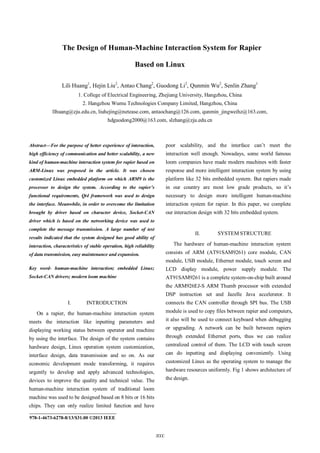
![Human-computer interface CAN
communication
module
Application layer
Kernel(including CAN
protocol family)
Linux OS layer
CAN drivers
AT91SAM9261
MPU
USB
LCD
Network
Touch screen
Flash SDRAM
CAN
controller
CAN
transceiver
Hardware layer
Data bus
Figure 1. Architecture of human-machine interaction system
III. CAN-BUS REALIZATION IN
ARM-LINUX ENVIRONMENT
In a rapier system, the other modules such as let-off
system are already extended with CAN control ports. The
CAN protocol is standardized in OSI model which
consists of data link layer, physical layer and application
layer. The controller implements the completion of the
protocol, and the transceiver converts the logic level
signals into the physical levels on the bus and vice versa.
A. The Hardware Design of CAN-Bus
The AT91SAM9261 module is extended with 64M
bytes SDRAM and 256M NAND Flash. Choosing
MCP2515 as the CAN controller, it is capable of
transmitting and receiving both standard and extended
data and remote frames. The MCP2515 interfaces with
MCU via Serial Peripheral Interface (SPI). For the
purpose of improving system reliability and noise
immunity, we connect high-speed
optocouplers-HCPL0600 between the controller and
transceiver.
B. The Design of Drivers of CAN-Bus Based on
ARM-Linux
The Linux way of looking at devices distinguishes
between three fundamental device types: char module,
block module, and network module. Each module usually
implements one of these types.
Before Socket-CAN [1], CAN implementations for
Linux is often based on character devices. Socket-CAN
uses the Berkeley socket API, the Linux network stack
and implements the CAN derives as network interface. It
overcomes some limitation brought by character device
implementations, like: Change of CAN hardware vendor
need to adapt the CAN application; complex filtering have
to be implemented in the applications in user space. In
Socket-CAN implementation, CAN frames from the
controller can be passed up to the networking layer and on
to the CAN protocol family modules, including the raw
socket protocol and the broadcast manager, and vice versa.
So it can use all of the provided queuing function in the
Linux networking layer.
Application
Application
Protocol
User space
Socket
CAN
protocol
family
Internet
protocol
family
Networking driver
Character
driver
kernel space
CAN controller CAN controller
Hardware space
Figure 2. Comparison of two kinds of driver
So the implementation of Socket-CAN consists of
two parts: A protocol family PF_CAN and the driver for
CAN networking devices. The new protocol family
PF_CAN transmits the frames in the networking layer and
provides useful user space utilities. The driver’s function
can be described as follows: Initializing and configuring
the hardware; pushing the incoming CAN frames from the
buffer of MCP2515 to the buffer of the upper layer;
transmitting the outgoing frames from the upper layer to
the bus. When the driver is loaded, the kernel calls the
driver’s “probe ()” function. This function performs the
basic initialization including arranging address ranges,
requesting IRQ numbers and configuring SPI function. By
calling “register_netdev ()” function, the device is
registered at the networking subsystem in the kernel.
Receive path: When arriving at the CAN controller,
the incoming message is stored in the receiving buffer of
MCP2515. Then an interrupt is aroused automatically.
2001](data:image/gif;base64,R0lGODlhAQABAIAAAAAAAP///yH5BAEAAAAALAAAAAABAAEAAAIBRAA7)
Recommended
More Related Content
What's hot
What's hot (20)
Similar to Engineer new post -hangzhou wumu technology co.,ltd.The Design of Human-Machine Interaction System for Rapier Based on Linux
Similar to Engineer new post -hangzhou wumu technology co.,ltd.The Design of Human-Machine Interaction System for Rapier Based on Linux (20)
Recently uploaded
Recently uploaded (20)
Engineer new post -hangzhou wumu technology co.,ltd.The Design of Human-Machine Interaction System for Rapier Based on Linux
- 1. The Design of Human-Machine Interaction System for Rapier Based on Linux Lili Huang1 , Hejin Liu2 , Antao Chang2 , Guodong Li2 , Qunmin Wu2 , Senlin Zhang1 1. College of Electrical Engineering, Zhejiang University, Hangzhou, China 2. Hangzhou Wumu Technologies Company Limited, Hangzhou, China llhuang@zju.edu.cn, liuhejing@netease.com, antaochang@126.com, qunmin_jingweihz@163.com, hdguodong2000@163.com, slzhang@zju.edu.cn Abstract—For the purpose of better experience of interaction, high efficiency of communication and better scalability, a new kind of human-machine interaction system for rapier based on ARM-Linux was proposed in the article. It was chosen customized Linux embedded platform on which ARM9 is the processor to design the system. According to the rapier’s functional requirements, Qt4 framework was used to design the interface. Meanwhile, in order to overcome the limitation brought by driver based on character device, Socket-CAN driver which is based on the networking device was used to complete the message transmission. A large number of test results indicated that the system designed has good ability of interaction, characteristics of stable operation, high reliability of data transmission, easy maintenance and expansion. Key word- human-machine interaction; embedded Linux; Socket-CAN drivers; modern loom machine I. INTRODUCTION On a rapier, the human-machine interaction system meets the interaction like inputting parameters and displaying working status between operator and machine by using the interface. The design of the system contains hardware design, Linux operation system customization, interface design, data transmission and so on. As our economic development mode transforming, it requires urgently to develop and apply advanced technologies, devices to improve the quality and technical value. The human-machine interaction system of traditional loom machine was used to be designed based on 8 bits or 16 bits chips. They can only realize limited function and have poor scalability, and the interface can’t meet the interaction well enough. Nowadays, some world famous loom companies have made modern machines with faster response and more intelligent interaction system by using platform like 32 bits embedded system. But rapiers made in our country are most low grade products, so it’s necessary to design more intelligent human-machine interaction system for rapier. In this paper, we complete our interaction design with 32 bits embedded system. II. SYSTEM STRUCTURE The hardware of human-machine interaction system consists of ARM (AT91SAM9261) core module, CAN module, USB module, Ethernet module, touch screen and LCD display module, power supply module. The AT91SAM9261 is a complete system-on-chip built around the ARM926EJ-S ARM Thumb processor with extended DSP instruction set and Jazelle Java accelerator. It connects the CAN controller through SPI bus. The USB module is used to copy files between rapier and computers, it also will be used to connect keyboard when debugging or upgrading. A network can be built between rapiers through extended Ethernet ports, thus we can realize centralized control of them. The LCD with touch screen can do inputting and displaying conveniently. Using customized Linux as the operating system to manage the hardware resources uniformly. Fig 1 shows architecture of the design. ____________________________________ 978-1-4673-6278-8/13/$31.00 ©2013 IEEE 2000
- 2. Human-computer interface CAN communication module Application layer Kernel(including CAN protocol family) Linux OS layer CAN drivers AT91SAM9261 MPU USB LCD Network Touch screen Flash SDRAM CAN controller CAN transceiver Hardware layer Data bus Figure 1. Architecture of human-machine interaction system III. CAN-BUS REALIZATION IN ARM-LINUX ENVIRONMENT In a rapier system, the other modules such as let-off system are already extended with CAN control ports. The CAN protocol is standardized in OSI model which consists of data link layer, physical layer and application layer. The controller implements the completion of the protocol, and the transceiver converts the logic level signals into the physical levels on the bus and vice versa. A. The Hardware Design of CAN-Bus The AT91SAM9261 module is extended with 64M bytes SDRAM and 256M NAND Flash. Choosing MCP2515 as the CAN controller, it is capable of transmitting and receiving both standard and extended data and remote frames. The MCP2515 interfaces with MCU via Serial Peripheral Interface (SPI). For the purpose of improving system reliability and noise immunity, we connect high-speed optocouplers-HCPL0600 between the controller and transceiver. B. The Design of Drivers of CAN-Bus Based on ARM-Linux The Linux way of looking at devices distinguishes between three fundamental device types: char module, block module, and network module. Each module usually implements one of these types. Before Socket-CAN [1], CAN implementations for Linux is often based on character devices. Socket-CAN uses the Berkeley socket API, the Linux network stack and implements the CAN derives as network interface. It overcomes some limitation brought by character device implementations, like: Change of CAN hardware vendor need to adapt the CAN application; complex filtering have to be implemented in the applications in user space. In Socket-CAN implementation, CAN frames from the controller can be passed up to the networking layer and on to the CAN protocol family modules, including the raw socket protocol and the broadcast manager, and vice versa. So it can use all of the provided queuing function in the Linux networking layer. Application Application Protocol User space Socket CAN protocol family Internet protocol family Networking driver Character driver kernel space CAN controller CAN controller Hardware space Figure 2. Comparison of two kinds of driver So the implementation of Socket-CAN consists of two parts: A protocol family PF_CAN and the driver for CAN networking devices. The new protocol family PF_CAN transmits the frames in the networking layer and provides useful user space utilities. The driver’s function can be described as follows: Initializing and configuring the hardware; pushing the incoming CAN frames from the buffer of MCP2515 to the buffer of the upper layer; transmitting the outgoing frames from the upper layer to the bus. When the driver is loaded, the kernel calls the driver’s “probe ()” function. This function performs the basic initialization including arranging address ranges, requesting IRQ numbers and configuring SPI function. By calling “register_netdev ()” function, the device is registered at the networking subsystem in the kernel. Receive path: When arriving at the CAN controller, the incoming message is stored in the receiving buffer of MCP2515. Then an interrupt is aroused automatically. 2001
- 3. Interrupt handler stores a notification into “softnet_data” queue and the message is read from the controller later. NET_RX_SOFTIRQ is called to place the frame into corresponding skb_queue. Transmit path: Sending messages is originated in the user space. When an application wants to send raw CAN frames, a CAN_RAW socket is opened and “send ()” system call is issued. The protocol copies the CAN frame into the kernel space and passes it to the packet scheduler. After that, the message transforms to CAN frame by calling “MCP2515_hw_tx ()” and write it to the CAN controller’s TX buffer by calling “MCP2515_hard_start_xmit ()” through SPI and the message will be sent onto the bus. CAN contoller IRQ handler Soft net_data queue Net_rx soft IRQ Skb_queue Applicaton CAN message IRQ skb Figure 3. Socket-CAN RX path C. Compiling and Loading the Driver of CAN-Bus There are two ways to make the driver working. The first is compiling the driver into the kernel statically. The other is making it as a module so that we can just need to load it when using it. We take the second way during our design because it can save memory and make the debugging conveniently. When generating CAN driver module, firstly, we have to point out the route of cross-compile chain in the file of “Makefile” on the host. Secondly, it’s necessary to let the compiler know that our target is ARM and our chain is “arm-linux-”. After executing command of “make”, a file tailed with “.ko” will be generated. The last job is to copy the file to the file system of the target, and execute “insmod”. IV. DESIGN OF THE INTERFACE AND COMPLETATION OF THE DATA INTERACTION A. Design of the Human-Machine Interface Qt is a cross-platform application framework that is widely used for developing application software with a graphical user interface. Because of its object-oriented programming, large quantity of documents and abundant of API for programming, we use Qt to design the interface, too. Qt/Embedded is a version used for embedded system which uses the same Qt libraries and API. So the interface can be designed on the host and then cross-compile the project to run on the target. The Qt libraries should be transplanted onto the ARM first. The function of the interface contains: Input operating parameters like angles of reading the tension before turn on the rapier; display some information when loom is working, like warp tension, rapier’s speed; deal with some counting such as stopping times, the length of weaved cloth; display warning messages when loom shuts down accidently. Some functions contained in the system are shown in Fig 4. User login Parameter setting Data access Data setting Status display Hardware testing Running data Weft choosing Warp setting Coiling setting status Warning message Work shift Date and time CAN bus testing Air break testing Motor setting Stop angle Sensor setting Weft feeder Weft unit stops Stop angle Speed tension Cloth length Writting INI Reading INI . . . File invokeing Figure 4. parameter scheme of HMI In Fig 4, the function of files’ invocation contains flower tissue’s copying and using, storage and management. We can copy tissues from external computers via USB port. All of the tissues stored in the system will be shown by using list view. The system carries along with the function of editing tissues of Dobby. Soft keyboard is used to input data. When a inputting edit-line gets the focus, the soft keyboard will eject immediately. And every time before turns up, the position will be update closely to the inputting area. The inputting 2002
- 4. data will be stored in the form of INI by using the class -“QSettings”. In order to prevent error inputting or operating, we use “QRegExp” class and regular expressions to limit the range of inputting. We also designed necessary dialog boxes to note the users whether they can do it or they will do it. All these measures can enhance the reliability of the system. When power on, the system will detect other modules. If any of them doesn’t work normally, the interface will give a message about the error. Even when the loom stops working accidently, the interface will also show warning message. In this way, the workers can fix the loom up quickly according to the point. The interface is designed like Fig 5. Status of rapier Parameter setting running parameters Weaved cloth Shift and efficiency Figure 5. The main interface B. Data Interaction In order to transmit messages among CAN nodes, CAN program should be completed in application. Since Socket-CAN protocol has provided interface for user space programming based on network, we just need to call “socket ()” function to open a socket. The socket uses the protocol family-PF_CAN which including CAN_RAW and CAN_BCM for broadcasting. Then bind the socket with CAN device and call “write ()” to send the message after finishing writing the frame. Or call “read ()” function to get the message on the bus. To ensure the screen real-time response to user’s operation, we use multi-thread programming method. One of the sub threads is dealing with data receiving exclusively. Once a sub thread is created, it is blocked until an appropriate event happened. So the processor has enough time to deal with other tasks. C. CAN Communication Protocol We custom the CAN communication protocol and configure the MCP2515 working on the Peli-CAN mode. Messages are transmitted via extended frame format which consists of 1 byte for frame information, 4 identifier bytes, and up to 8 data bytes. Since a frame has higher priority when it has smaller ID, different frame types are defined. ID13-ID16 is used to distinguish the warning message, command message, broadcast frame, multi-frame etc. ID28 ID27 ID26 ID25 ID24 ID23 ID22 ID21 ID20 ID19 Frame type Source address ID18 ID17 ID16 ID15 ID14 ID13 ID12 ID11 ID10 ID9 Destination address reserved ID8 ID7 ID6 ID5 ID4 ID3 ID2 ID1 ID0 Functional code Functional code Figure 6. Definition of frame ID V. CONCLUSIONS The human-machine interaction system is a key node of rapier control system. The interface designed based on embedded Linux has good portability and scalability. It’s also easy to be maintained and upgraded. By using Qt4 framework, color LCD with extended TFT format and touch screen, the interaction between operator and machine is convenient. Modular design method, reasonable controls’ layout and better fault tolerance make the interface more humanity. Using multi-thread technology ensures that the response is quick enough. In practice, the system communicates with other CAN nodes in speed of 250kbps. The result proves that it works stably and data transmit correctly. This work can be useful for designing modern loom machine. 2003
- 5. REFERENCE [1] “The SocketCAN project websites,” http://developer.berlios.de/projects/socketcan. [2] Su Rongyan, Chang Jiupeng, and Shao Liqing, Deng Kangyao, “Design of Test Control System Interface Communication Card in Engine Based on CAN Bus,” Micro Computer Information, 2005,1,101 - 103. [3] Li Dinggen, Chen Jun, and Wu Zhaohui, “Research and development of in-vehicle information platform based on Arm-Linux ,” Journal of Zhejiang University (Engineering Science), Vol.40, Sep.2006. [4] Wang Hongkai, and Zhang Senlin, “Design of the software system of automaitc flat knitting machine based on Linux embedded technology,” Journal of Textile Research, Vol.29, Feb.2008. [5] T. Nolte, M. Nolin, and H. Hansson, “Real-time server-based communication for CAN,” IEEE Transactions on Industrial Informatics, Vol.1(3), pp.192 - 201, 2005. [6] Zhao Bing, “Roving frame control system based on CAN bus,” Journey of Textile Research, 2006, Vol.27(5), pp.84 - 86. 2004