SlideShare a Scribd company logo
1 of 6
Ha, Stephanie
December 1, 2008
EXPERIMENT 20: DESIGN OF SYNCHRONOUS COUNTERS POST-LAB
Summary
In this experiment, a synchronous counter was constructed based on the state diagram
presented in the Figure 20-1 in the data section. From Table 20-1, the Karnaugh maps (Figure
20-2) for each flip-flop were obtained after determining the inputs of each flip-flop.
From Figure 20-2, the circuit was constructed based on these equations. Figure 20-3
illustrates a schematic of the circuit where flip-flop C is the most significant. In constructing the
circuit, it was determined that ‘011’ went to the next state of ‘000’ instead of ‘010’.
From the previous experiment, the circuit was then debugged to find that QB was not
working properly. Each flip-flop was tested with a logic indicator to verify its output. It was
found that KB was not working properly: it was connected to QC’ (pin14) instead of QC (pin15).
Making the appropriate change, the circuit worked properly.
The next state for unused states 5 and 7 can be determined through various methods. One
method is from the previous experiment where the sequence can be determined to set and reset
the value to state 5 and state 7 and then use a pushbutton switch to reset these values. Another is
to use Table 20-2, Table 20-3, and Figure 20-3 to determine the input of each flip from its K-
map.
Data
Figure 20-1: Required Sequence for Circuit
1
Table 20-2: State Table and Flip-Flop for Circuit
Present State Next State Flip-Flops
qC qB qA QC QB QA JC KC JB KB JA KA
0 0 0 0 0 1 0 x 0 x 1 x
0 0 1 0 1 1 0 x 1 x x 0
0 1 1 0 1 0 0 x x 0 x 1
0 1 0 1 1 0 1 x x 0 0 x
1 1 0 1 0 0 x 0 x 1 0 x
1 0 0 0 0 0 x 1 x 0 0 x
1 0 1 x x x x x x x x x
1 1 1 x x x x x x x x x
*Note: Highlighted areas indicate unused state
Figure 20-2: Karnaugh Maps for JK Flip-Flops
Figure 20-3: Schematic for Circuit from equations in Figure 20-2
Review Questions
1. Complete the design for the sequential counter in Figure 20-3 by constructing Karnaugh
maps for the B and A flip-flops. Read the maps. As a check, you can compare your result
with the circuit drawn in Figure 19-1.
2
State Diagram for Fig. 20-3
State Table and Excitation Table for Flip-Flops
Present State Next State Flip-Flops
qD qC qB qA QD QC QB QA JD KD JC KC JB KB JA KA
0 0 0 1 0 0 1 1 0 x 0 x 1 x x 0
0 0 1 1 0 0 1 0 0 x 0 x x 0 x 1
0 0 1 0 0 1 1 0 0 x 1 x x 0 0 x
0 1 1 0 0 1 0 0 0 x x 0 x 1 0 x
0 1 0 0 1 1 0 0 1 x x 0 0 x 0 x
1 1 0 0 1 0 0 0 x 0 x 1 0 x 0 x
1 0 0 0 1 0 0 1 x 0 0 x 0 x 1 x
1 0 0 1 0 0 0 1 x 1 0 x 0 x 0 x
Karnaugh Maps for Fig. 20-3 (D + C Flip-Flops)
3
2. Describe the logic necessary to add a seven-segment display to the circuit you designed in
this experiment to enable the display to show the state of the counter.
a. Connect seven-segment display, MAN72 to seven-segment to BCD decoder or 7447A
(from previous experiment). Connect flip-flops to inputs of 7447A (DCBA) with C being
the most significant.
3. Assume you wanted to make the sequential circuit you designed in this experiment start in
state 5 if a reset pushbutton is pressed. Describe how you would modify the circuit to
incorporate this feature.
a. Derive the K-map for state 5Connect clocks C and A together to push button switch,
leaving B grounded to obtain a clock of ‘101’. Leave all other connections as it is.
4. Assume you wanted to change the circuit from this experiment to be able to reverse the
sequence. How would you go about this?
a. Start all over again (repeat process) by reversing the state diagram for the circuit in the
experiment.
i. State Diagram
4
ii. State table
Present State Next State Flip-Flops
qC qB qA QC QB QA JC KC JB KB JA KA
0 0 0 1 0 0 1 x 0 x 0 x
1 0 0 1 1 0 x 0 1 x 0 x
1 1 0 0 1 0 x 1 x 0 0 x
0 1 0 0 1 1 0 x x 0 1 x
0 1 1 0 0 1 0 x x 1 x 0
0 0 1 0 0 0 0 x 0 x x 1
iii. K-Maps
iv. Construct circuit based on K-map (not shown)
5
ii. State table
Present State Next State Flip-Flops
qC qB qA QC QB QA JC KC JB KB JA KA
0 0 0 1 0 0 1 x 0 x 0 x
1 0 0 1 1 0 x 0 1 x 0 x
1 1 0 0 1 0 x 1 x 0 0 x
0 1 0 0 1 1 0 x x 0 1 x
0 1 1 0 0 1 0 x x 1 x 0
0 0 1 0 0 0 0 x 0 x x 1
iii. K-Maps
iv. Construct circuit based on K-map (not shown)
5

More Related Content

What's hot

Bài giảng môn học siemens plc s7 – 300
Bài giảng môn học siemens plc s7 – 300Bài giảng môn học siemens plc s7 – 300
Bài giảng môn học siemens plc s7 – 300Lê Gia
 
Các phần tử trong hệ thống điều khiển khí nén
Các phần tử trong hệ thống điều khiển khí nénCác phần tử trong hệ thống điều khiển khí nén
Các phần tử trong hệ thống điều khiển khí nénjackjohn45
 
Robot scara
Robot scaraRobot scara
Robot scaraTrung Le
 
Cách tạo chân linh kiện trong Orcad Layout P1
Cách tạo chân linh kiện trong Orcad Layout P1Cách tạo chân linh kiện trong Orcad Layout P1
Cách tạo chân linh kiện trong Orcad Layout P1Vuong Do
 
4.2.1. thiết kế bộ điều khiển trượt cho robot 2 bậc tự do và mô phỏng trên ma...
4.2.1. thiết kế bộ điều khiển trượt cho robot 2 bậc tự do và mô phỏng trên ma...4.2.1. thiết kế bộ điều khiển trượt cho robot 2 bậc tự do và mô phỏng trên ma...
4.2.1. thiết kế bộ điều khiển trượt cho robot 2 bậc tự do và mô phỏng trên ma...TÀI LIỆU NGÀNH MAY
 
Các phương pháp thiết kế bộ điều khiển PID.docx
Các phương pháp thiết kế bộ điều khiển PID.docxCác phương pháp thiết kế bộ điều khiển PID.docx
Các phương pháp thiết kế bộ điều khiển PID.docxhunhlhongthi
 
Điều khiển cánh tay Robot học lệnh gắp sản phẩm trên băng chuyền.pdf
Điều khiển cánh tay Robot học lệnh gắp sản phẩm trên băng chuyền.pdfĐiều khiển cánh tay Robot học lệnh gắp sản phẩm trên băng chuyền.pdf
Điều khiển cánh tay Robot học lệnh gắp sản phẩm trên băng chuyền.pdfMan_Ebook
 
Viết biểu thức U-I trong mạch xoay chiều
Viết biểu thức U-I trong mạch xoay chiềuViết biểu thức U-I trong mạch xoay chiều
Viết biểu thức U-I trong mạch xoay chiềutuituhoc
 
ĐIều khiển con lắc ngược quay
ĐIều khiển con lắc ngược quayĐIều khiển con lắc ngược quay
ĐIều khiển con lắc ngược quayMan_Ebook
 
Điều khiển điện tử công suất DCDC bộ BUCK.pdf
Điều khiển điện tử công suất DCDC bộ BUCK.pdfĐiều khiển điện tử công suất DCDC bộ BUCK.pdf
Điều khiển điện tử công suất DCDC bộ BUCK.pdfNguynCnh45
 
Mealy state machine
Mealy state machineMealy state machine
Mealy state machineArif Siyal
 
Kỹ thuật điện tử - bài tập diode
Kỹ thuật điện tử - bài tập diodeKỹ thuật điện tử - bài tập diode
Kỹ thuật điện tử - bài tập diodecanhbao
 
Nghiên cứu phát triển một số thuật toán điều khiển rô bốt di động có tính đến...
Nghiên cứu phát triển một số thuật toán điều khiển rô bốt di động có tính đến...Nghiên cứu phát triển một số thuật toán điều khiển rô bốt di động có tính đến...
Nghiên cứu phát triển một số thuật toán điều khiển rô bốt di động có tính đến...Man_Ebook
 
mealy and moore machines
mealy and moore machinesmealy and moore machines
mealy and moore machinesUnsa Shakir
 
Logic Design - Chapter 2: Logic Gates
Logic Design - Chapter 2: Logic GatesLogic Design - Chapter 2: Logic Gates
Logic Design - Chapter 2: Logic GatesGouda Mando
 
Điều khiển dự báo phản hồi đầu ra theo nguyên lý tách cho hệ phi tuyến.pdf
Điều khiển dự báo phản hồi đầu ra theo nguyên lý tách cho hệ phi tuyến.pdfĐiều khiển dự báo phản hồi đầu ra theo nguyên lý tách cho hệ phi tuyến.pdf
Điều khiển dự báo phản hồi đầu ra theo nguyên lý tách cho hệ phi tuyến.pdfMan_Ebook
 

What's hot (20)

Bài giảng môn học siemens plc s7 – 300
Bài giảng môn học siemens plc s7 – 300Bài giảng môn học siemens plc s7 – 300
Bài giảng môn học siemens plc s7 – 300
 
Các phần tử trong hệ thống điều khiển khí nén
Các phần tử trong hệ thống điều khiển khí nénCác phần tử trong hệ thống điều khiển khí nén
Các phần tử trong hệ thống điều khiển khí nén
 
Robot scara
Robot scaraRobot scara
Robot scara
 
197e
197e197e
197e
 
Cách tạo chân linh kiện trong Orcad Layout P1
Cách tạo chân linh kiện trong Orcad Layout P1Cách tạo chân linh kiện trong Orcad Layout P1
Cách tạo chân linh kiện trong Orcad Layout P1
 
4.2.1. thiết kế bộ điều khiển trượt cho robot 2 bậc tự do và mô phỏng trên ma...
4.2.1. thiết kế bộ điều khiển trượt cho robot 2 bậc tự do và mô phỏng trên ma...4.2.1. thiết kế bộ điều khiển trượt cho robot 2 bậc tự do và mô phỏng trên ma...
4.2.1. thiết kế bộ điều khiển trượt cho robot 2 bậc tự do và mô phỏng trên ma...
 
Trang bi dien thang may
Trang bi dien thang mayTrang bi dien thang may
Trang bi dien thang may
 
Các phương pháp thiết kế bộ điều khiển PID.docx
Các phương pháp thiết kế bộ điều khiển PID.docxCác phương pháp thiết kế bộ điều khiển PID.docx
Các phương pháp thiết kế bộ điều khiển PID.docx
 
Điều khiển cánh tay Robot học lệnh gắp sản phẩm trên băng chuyền.pdf
Điều khiển cánh tay Robot học lệnh gắp sản phẩm trên băng chuyền.pdfĐiều khiển cánh tay Robot học lệnh gắp sản phẩm trên băng chuyền.pdf
Điều khiển cánh tay Robot học lệnh gắp sản phẩm trên băng chuyền.pdf
 
Viết biểu thức U-I trong mạch xoay chiều
Viết biểu thức U-I trong mạch xoay chiềuViết biểu thức U-I trong mạch xoay chiều
Viết biểu thức U-I trong mạch xoay chiều
 
ĐIều khiển con lắc ngược quay
ĐIều khiển con lắc ngược quayĐIều khiển con lắc ngược quay
ĐIều khiển con lắc ngược quay
 
Half adder layout design
Half adder layout designHalf adder layout design
Half adder layout design
 
Điều khiển điện tử công suất DCDC bộ BUCK.pdf
Điều khiển điện tử công suất DCDC bộ BUCK.pdfĐiều khiển điện tử công suất DCDC bộ BUCK.pdf
Điều khiển điện tử công suất DCDC bộ BUCK.pdf
 
Mealy state machine
Mealy state machineMealy state machine
Mealy state machine
 
Kỹ thuật điện tử - bài tập diode
Kỹ thuật điện tử - bài tập diodeKỹ thuật điện tử - bài tập diode
Kỹ thuật điện tử - bài tập diode
 
Nghiên cứu phát triển một số thuật toán điều khiển rô bốt di động có tính đến...
Nghiên cứu phát triển một số thuật toán điều khiển rô bốt di động có tính đến...Nghiên cứu phát triển một số thuật toán điều khiển rô bốt di động có tính đến...
Nghiên cứu phát triển một số thuật toán điều khiển rô bốt di động có tính đến...
 
Ltdktd2
Ltdktd2Ltdktd2
Ltdktd2
 
mealy and moore machines
mealy and moore machinesmealy and moore machines
mealy and moore machines
 
Logic Design - Chapter 2: Logic Gates
Logic Design - Chapter 2: Logic GatesLogic Design - Chapter 2: Logic Gates
Logic Design - Chapter 2: Logic Gates
 
Điều khiển dự báo phản hồi đầu ra theo nguyên lý tách cho hệ phi tuyến.pdf
Điều khiển dự báo phản hồi đầu ra theo nguyên lý tách cho hệ phi tuyến.pdfĐiều khiển dự báo phản hồi đầu ra theo nguyên lý tách cho hệ phi tuyến.pdf
Điều khiển dự báo phản hồi đầu ra theo nguyên lý tách cho hệ phi tuyến.pdf
 

Viewers also liked

[Speech3] Draft002
[Speech3] Draft002[Speech3] Draft002
[Speech3] Draft002Stephanie Ha
 
[EXPERIMENT6+7] Heat_treatment_and_Hardenability
[EXPERIMENT6+7] Heat_treatment_and_Hardenability[EXPERIMENT6+7] Heat_treatment_and_Hardenability
[EXPERIMENT6+7] Heat_treatment_and_HardenabilityStephanie Ha
 
BIOLOGY03FinalStudyGuide
BIOLOGY03FinalStudyGuideBIOLOGY03FinalStudyGuide
BIOLOGY03FinalStudyGuideStephanie Ha
 
[EXPERIMENT2] CHARPY IMPACT TESTING MEMO REPORT
[EXPERIMENT2] CHARPY IMPACT TESTING MEMO REPORT[EXPERIMENT2] CHARPY IMPACT TESTING MEMO REPORT
[EXPERIMENT2] CHARPY IMPACT TESTING MEMO REPORTStephanie Ha
 

Viewers also liked (8)

Individual
IndividualIndividual
Individual
 
[Speech3] Draft002
[Speech3] Draft002[Speech3] Draft002
[Speech3] Draft002
 
[EXPERIMENT6+7] Heat_treatment_and_Hardenability
[EXPERIMENT6+7] Heat_treatment_and_Hardenability[EXPERIMENT6+7] Heat_treatment_and_Hardenability
[EXPERIMENT6+7] Heat_treatment_and_Hardenability
 
BIOLOGY03FinalStudyGuide
BIOLOGY03FinalStudyGuideBIOLOGY03FinalStudyGuide
BIOLOGY03FinalStudyGuide
 
Technical_Report
Technical_ReportTechnical_Report
Technical_Report
 
[EXPERIMENT2] CHARPY IMPACT TESTING MEMO REPORT
[EXPERIMENT2] CHARPY IMPACT TESTING MEMO REPORT[EXPERIMENT2] CHARPY IMPACT TESTING MEMO REPORT
[EXPERIMENT2] CHARPY IMPACT TESTING MEMO REPORT
 
Counters
CountersCounters
Counters
 
Chapter 5 counter
Chapter 5 counterChapter 5 counter
Chapter 5 counter
 

Similar to [EXPERIMENT20] DeSIGN OF SYNCHRONOUS COUNTERS

Logic Design - Chapter 7: Sequential Circuit Analysis and Design
Logic Design - Chapter 7: Sequential Circuit Analysis and DesignLogic Design - Chapter 7: Sequential Circuit Analysis and Design
Logic Design - Chapter 7: Sequential Circuit Analysis and DesignGouda Mando
 
Sequential logic circuit
Sequential logic circuitSequential logic circuit
Sequential logic circuitAswiniT3
 
Electrónica digital: Diseño de contador con flip-flop tipo JK y D haciendo de...
Electrónica digital: Diseño de contador con flip-flop tipo JK y D haciendo de...Electrónica digital: Diseño de contador con flip-flop tipo JK y D haciendo de...
Electrónica digital: Diseño de contador con flip-flop tipo JK y D haciendo de...SANTIAGO PABLO ALBERTO
 
EET107_Chapter 3_SLD(part2.1)-edit1.ppt
EET107_Chapter 3_SLD(part2.1)-edit1.pptEET107_Chapter 3_SLD(part2.1)-edit1.ppt
EET107_Chapter 3_SLD(part2.1)-edit1.pptBeautyKumar1
 
NR-Power Flow.pdf
NR-Power Flow.pdfNR-Power Flow.pdf
NR-Power Flow.pdfLucasMogaka
 
Eceg 3201-dld-lec 12-synchronous_counter_design
Eceg 3201-dld-lec 12-synchronous_counter_designEceg 3201-dld-lec 12-synchronous_counter_design
Eceg 3201-dld-lec 12-synchronous_counter_designNebiyu Musie
 
Quantum Computing Notes Ver 1.2
Quantum Computing Notes Ver 1.2Quantum Computing Notes Ver 1.2
Quantum Computing Notes Ver 1.2Vijayananda Mohire
 
Stld unit 5
Stld  unit 5Stld  unit 5
Stld unit 5azeez786
 
L-24(DK&SSG)(PE) ((EE)NPTEL) (4 files merged).pdf
L-24(DK&SSG)(PE) ((EE)NPTEL) (4 files merged).pdfL-24(DK&SSG)(PE) ((EE)NPTEL) (4 files merged).pdf
L-24(DK&SSG)(PE) ((EE)NPTEL) (4 files merged).pdfsatyam jha
 
Newton raphson method
Newton raphson methodNewton raphson method
Newton raphson methodNazrul Kabir
 
Sequential Circuits-ppt_2.pdf
Sequential Circuits-ppt_2.pdfSequential Circuits-ppt_2.pdf
Sequential Circuits-ppt_2.pdfimadshaheen2
 
Sequential Circuitsdddddddddddddddddsssssssssss-ppt.pptx
Sequential Circuitsdddddddddddddddddsssssssssss-ppt.pptxSequential Circuitsdddddddddddddddddsssssssssss-ppt.pptx
Sequential Circuitsdddddddddddddddddsssssssssss-ppt.pptxAhmedAlAfandi5
 
04 sequential circuits
04 sequential circuits04 sequential circuits
04 sequential circuitsxyxz
 

Similar to [EXPERIMENT20] DeSIGN OF SYNCHRONOUS COUNTERS (20)

Logic Design - Chapter 7: Sequential Circuit Analysis and Design
Logic Design - Chapter 7: Sequential Circuit Analysis and DesignLogic Design - Chapter 7: Sequential Circuit Analysis and Design
Logic Design - Chapter 7: Sequential Circuit Analysis and Design
 
Sequential logic circuit
Sequential logic circuitSequential logic circuit
Sequential logic circuit
 
1سلمي 2
1سلمي 21سلمي 2
1سلمي 2
 
Electrónica digital: Diseño de contador con flip-flop tipo JK y D haciendo de...
Electrónica digital: Diseño de contador con flip-flop tipo JK y D haciendo de...Electrónica digital: Diseño de contador con flip-flop tipo JK y D haciendo de...
Electrónica digital: Diseño de contador con flip-flop tipo JK y D haciendo de...
 
Informe display 7 segmentos
Informe display 7 segmentosInforme display 7 segmentos
Informe display 7 segmentos
 
Karnaugh maps z 88
Karnaugh maps   z  88Karnaugh maps   z  88
Karnaugh maps z 88
 
EET107_Chapter 3_SLD(part2.1)-edit1.ppt
EET107_Chapter 3_SLD(part2.1)-edit1.pptEET107_Chapter 3_SLD(part2.1)-edit1.ppt
EET107_Chapter 3_SLD(part2.1)-edit1.ppt
 
NR-Power Flow.pdf
NR-Power Flow.pdfNR-Power Flow.pdf
NR-Power Flow.pdf
 
Problemset3 278
Problemset3 278Problemset3 278
Problemset3 278
 
Eceg 3201-dld-lec 12-synchronous_counter_design
Eceg 3201-dld-lec 12-synchronous_counter_designEceg 3201-dld-lec 12-synchronous_counter_design
Eceg 3201-dld-lec 12-synchronous_counter_design
 
Quantum Computing Notes Ver 1.2
Quantum Computing Notes Ver 1.2Quantum Computing Notes Ver 1.2
Quantum Computing Notes Ver 1.2
 
Stld unit 5
Stld  unit 5Stld  unit 5
Stld unit 5
 
L-24(DK&SSG)(PE) ((EE)NPTEL) (4 files merged).pdf
L-24(DK&SSG)(PE) ((EE)NPTEL) (4 files merged).pdfL-24(DK&SSG)(PE) ((EE)NPTEL) (4 files merged).pdf
L-24(DK&SSG)(PE) ((EE)NPTEL) (4 files merged).pdf
 
Newton raphson method
Newton raphson methodNewton raphson method
Newton raphson method
 
Eca unit 2
Eca unit 2Eca unit 2
Eca unit 2
 
Sequential Circuits-ppt_2.pdf
Sequential Circuits-ppt_2.pdfSequential Circuits-ppt_2.pdf
Sequential Circuits-ppt_2.pdf
 
Sequential Circuitsdddddddddddddddddsssssssssss-ppt.pptx
Sequential Circuitsdddddddddddddddddsssssssssss-ppt.pptxSequential Circuitsdddddddddddddddddsssssssssss-ppt.pptx
Sequential Circuitsdddddddddddddddddsssssssssss-ppt.pptx
 
04 sequential circuits
04 sequential circuits04 sequential circuits
04 sequential circuits
 
POWER SYSTEM 2
POWER SYSTEM 2POWER SYSTEM 2
POWER SYSTEM 2
 
99992505.pdf
99992505.pdf99992505.pdf
99992505.pdf
 

[EXPERIMENT20] DeSIGN OF SYNCHRONOUS COUNTERS

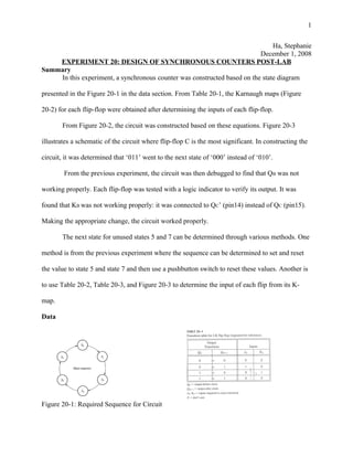
  • 1. Ha, Stephanie December 1, 2008 EXPERIMENT 20: DESIGN OF SYNCHRONOUS COUNTERS POST-LAB Summary In this experiment, a synchronous counter was constructed based on the state diagram presented in the Figure 20-1 in the data section. From Table 20-1, the Karnaugh maps (Figure 20-2) for each flip-flop were obtained after determining the inputs of each flip-flop. From Figure 20-2, the circuit was constructed based on these equations. Figure 20-3 illustrates a schematic of the circuit where flip-flop C is the most significant. In constructing the circuit, it was determined that ‘011’ went to the next state of ‘000’ instead of ‘010’. From the previous experiment, the circuit was then debugged to find that QB was not working properly. Each flip-flop was tested with a logic indicator to verify its output. It was found that KB was not working properly: it was connected to QC’ (pin14) instead of QC (pin15). Making the appropriate change, the circuit worked properly. The next state for unused states 5 and 7 can be determined through various methods. One method is from the previous experiment where the sequence can be determined to set and reset the value to state 5 and state 7 and then use a pushbutton switch to reset these values. Another is to use Table 20-2, Table 20-3, and Figure 20-3 to determine the input of each flip from its K- map. Data Figure 20-1: Required Sequence for Circuit 1
  • 2. Table 20-2: State Table and Flip-Flop for Circuit Present State Next State Flip-Flops qC qB qA QC QB QA JC KC JB KB JA KA 0 0 0 0 0 1 0 x 0 x 1 x 0 0 1 0 1 1 0 x 1 x x 0 0 1 1 0 1 0 0 x x 0 x 1 0 1 0 1 1 0 1 x x 0 0 x 1 1 0 1 0 0 x 0 x 1 0 x 1 0 0 0 0 0 x 1 x 0 0 x 1 0 1 x x x x x x x x x 1 1 1 x x x x x x x x x *Note: Highlighted areas indicate unused state Figure 20-2: Karnaugh Maps for JK Flip-Flops Figure 20-3: Schematic for Circuit from equations in Figure 20-2 Review Questions 1. Complete the design for the sequential counter in Figure 20-3 by constructing Karnaugh maps for the B and A flip-flops. Read the maps. As a check, you can compare your result with the circuit drawn in Figure 19-1. 2
  • 3. State Diagram for Fig. 20-3 State Table and Excitation Table for Flip-Flops Present State Next State Flip-Flops qD qC qB qA QD QC QB QA JD KD JC KC JB KB JA KA 0 0 0 1 0 0 1 1 0 x 0 x 1 x x 0 0 0 1 1 0 0 1 0 0 x 0 x x 0 x 1 0 0 1 0 0 1 1 0 0 x 1 x x 0 0 x 0 1 1 0 0 1 0 0 0 x x 0 x 1 0 x 0 1 0 0 1 1 0 0 1 x x 0 0 x 0 x 1 1 0 0 1 0 0 0 x 0 x 1 0 x 0 x 1 0 0 0 1 0 0 1 x 0 0 x 0 x 1 x 1 0 0 1 0 0 0 1 x 1 0 x 0 x 0 x Karnaugh Maps for Fig. 20-3 (D + C Flip-Flops) 3
  • 4. 2. Describe the logic necessary to add a seven-segment display to the circuit you designed in this experiment to enable the display to show the state of the counter. a. Connect seven-segment display, MAN72 to seven-segment to BCD decoder or 7447A (from previous experiment). Connect flip-flops to inputs of 7447A (DCBA) with C being the most significant. 3. Assume you wanted to make the sequential circuit you designed in this experiment start in state 5 if a reset pushbutton is pressed. Describe how you would modify the circuit to incorporate this feature. a. Derive the K-map for state 5Connect clocks C and A together to push button switch, leaving B grounded to obtain a clock of ‘101’. Leave all other connections as it is. 4. Assume you wanted to change the circuit from this experiment to be able to reverse the sequence. How would you go about this? a. Start all over again (repeat process) by reversing the state diagram for the circuit in the experiment. i. State Diagram 4
  • 5. ii. State table Present State Next State Flip-Flops qC qB qA QC QB QA JC KC JB KB JA KA 0 0 0 1 0 0 1 x 0 x 0 x 1 0 0 1 1 0 x 0 1 x 0 x 1 1 0 0 1 0 x 1 x 0 0 x 0 1 0 0 1 1 0 x x 0 1 x 0 1 1 0 0 1 0 x x 1 x 0 0 0 1 0 0 0 0 x 0 x x 1 iii. K-Maps iv. Construct circuit based on K-map (not shown) 5
  • 6. ii. State table Present State Next State Flip-Flops qC qB qA QC QB QA JC KC JB KB JA KA 0 0 0 1 0 0 1 x 0 x 0 x 1 0 0 1 1 0 x 0 1 x 0 x 1 1 0 0 1 0 x 1 x 0 0 x 0 1 0 0 1 1 0 x x 0 1 x 0 1 1 0 0 1 0 x x 1 x 0 0 0 1 0 0 0 0 x 0 x x 1 iii. K-Maps iv. Construct circuit based on K-map (not shown) 5