Mdwt final ppt 1
•Download as PPTX, PDF•
1 like•336 views

MDWT is a wind turbine.which has a very good efficiency.

Recommended
Recommended
More Related Content
What's hot
What's hot (20)
Similar to Mdwt final ppt 1
Similar to Mdwt final ppt 1 (20)
Recently uploaded
Recently uploaded (20)
Mdwt final ppt 1
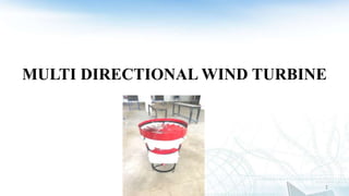
- 1. MULTI DIRECTIONAL WIND TURBINE 1
- 2. Introduction • Wind power is the conversion of wind energy into electricity or mechanical energy using wind turbines. • Wind power generation capacity in India is 49,130 MW (as per 2010 Wind Atlas). • This project presents a new multi directional wind turbine can capture wind energy on building rooftops. • Our aim is to harvest turbulent urban/ industrial wind at low speed from any direction. 2
- 3. Literature Review 3 SL NO TITLE AUTHORS NAME YEAR 1 Electricity generation from Windmill and performance analysis Amit Roy, Md. Rokunuzzaman JMEST Vol 2 issue 6 2015 june 2 Innovative Multi Directional Wind Turbine Sevvel p, Santhosh p IJIRSET Vol 3 issue 3 2014 march 3 Wind Turbine Blade Efficiency and Power Calculation with Elecrical Analogy Asis Sarkar, Dhiren kumar Behera ISSN Vol 2 issue 2 2012 feb
- 4. Methodology Data Collection Material Selection Design of Components Analyzing using Software Fabrication of Components AssemblyTesting Results and Conclusion 4
- 5. Working Principle • The energy in the wind turns the propeller like blades around a rotor. • The rotor is connected to the main shaft, which spins a generator to create electricity. • Wind turbines can be used to produce electricity for a single home or building. • They can be connected to an electricity grid for more widespread electricity distribution. 5
- 6. 6
- 7. Construction • Aerodynamic modeling is used to determine optimum height, number of blades and blade shape. • Multi Directional Wind Turbine (MDWT) can be divided into three components: Rotor component General component Structural support component 7
- 8. Aerodynamics • Shape and dimensions of the blades are determined by the aerodynamic performance required to efficiently extract energy from the wind. • The air flow at the blades is not the same as the airflow far away from the turbine. • The aerodynamics of a wind turbine at the rotor surface exhibit phenomena that are rarely seen in other aerodynamic fields. 8
- 9. Aerodynamics (Cont…) 9 Aerofoil vertical support wall with air bleed channels Toroid blade with air bleed channels
- 10. Power Control • All wind turbines are designed for a maximum wind speed, called the survival speed. • Survival speed of commercial wind turbines:144km/h to 259 km/h. • If the rated wind speed is exceeded, the power has to be limited. 10
- 11. Design Calculations • Tip Speed Ratio: TSR = Tip speed of blade / Wind speed Typical TSR for slow running is 1 to 4 and for fast running 5 to 7. • Number of Blades: In vertical wind mills, best number is 15 or more for smooth and steady rotation. In MDWT, we use 17 blades for proper design. • Angle of Attack (Blade Angle): Typical blade angle is 4º with flight direction. Sometimes 30º or 45º blade angles are used. • Wind Speed: Based on the criteria with the power, rpm, blade chord of the windmill, the wind velocity is 7 m/s 11
- 13. Design Calculations (Cont…) • The rotor, blades and casing with toroid blades are constructed according to the dimensions. 13 Designated front view and top view of rotor and casing
- 14. Computational Study • Computational Fluid Dynamics (CFD): Analyzing the aerodynamics in the study of wind turbines. • Steps required to CFD Analysis: • Defining the Modeling Goals • Creating Model Geometry • Defining and Creating Mesh 14 • Setting up the Solver and Physics • Monitoring the Solution • Evaluating the Solution through Results • Revising the Model *
- 15. Computational Study (Cont…) Creating Model Geometry 15Model geometry
- 16. Computational Study (Cont…) Defining and Creating Mesh 16 Model geometry after meshing *
- 17. Fabrication • Turbine Size: To minimize costs, wind farm turbines are basically limited by the strength of materials, and sitting requirements. 17 • Nacelle: It is housing the gearbox and generator connecting the tower and rotor. • Gear Box: It converts the turning speed of the blades into 15 to 20 rpm.
- 18. Fabrication (Cont…) • Center Shaft: It consists of a single 56cm length and 2.5cm in diameter. A solid shaft rotating at 75 rpm is assumed to be made of copper. 18 Rotor blade and shaft • Bearing: For the smooth operation of Shaft, bearing mechanism is used. Bearing has diameter of 2.5cm.
- 19. Fabrication (Cont…) • Generator: For reducing the cost and weight, gearbox is inserted between the rotor hub and the generator. • Blade Design: Use of aluminum and composite materials lower rotational inertia. Number of blades are selected for aerodynamic efficiency. • Blade material: Smaller blades can be made from light metals such as aluminium. 19
- 20. Fabrication (Cont…) 20 Mechanical components of wind turbine Electrical components of wind turbine
- 21. Result 21 Graph showing Speed v/s Wind speed Graph showing output power v/s Wind speed
- 22. Result (Cont…) 22 Graph showing Turbine efficiency vs Speed
- 23. Result (Cont…) • The figure below shows the result obtained by performing Computational Fluid Dynamics analysis using Ansys 15.0 Fluent computer software. 23
- 24. Result (Cont…) 24 Velocity stream line with pressure
- 25. Result (Cont…) 25 Velocity stream line
- 26. Cost Analysis 26
- 27. Conclusion • This project has approach to a new model of multi directional wind turbine that enables the wind from any direction. • The theoretical and practical ideas presented in this project have been applied to real world eliminating the present environmental issues. • This work differs from existing approaches will become a big success in future generation. 27
- 28. Reference • A Review: Aerodynamic Analysis On Vertical Axis WindTurbine Blade. Girish M Prajapati Abrarkhan Pathan Mr. B J Patel. Volume 1, Issue 12, December -2014. • Comparison of Horizontal Axis Wind Turbines and Vertical Axis Wind Turbines Muthu Manokar Vol. 04, Issue 08 (August. 2014). • Design and analysis of highway windmill electric generation Norzelawati Asmuin volume-03, Issue-07, pp-28-32 (2014). • Design and Analysis of Vertical Axis Wind Turbine F.Farooq Vol. 4, Issue, 2, pp. 313-315, February (2014). • Design, Development and Testing of a Combined Savonius and Darrieus Vertical Axis Wind Turbine M. Abid, K. S. Karimov, H. A. Wajid, F. Farooq, H. Ahmed, O. H. Khan (2015). • www.energy.gov/eere • www.indianwindpower.com • www.explainthatstuff.com/windturbine 28
- 29. Thank You 29