2. 168 J. Nicks
b. Flow
c. Volume
2. Loops
a. Pressure–volume loop
b. Flow–volume loop
3. Mechanics
a. Dynamic compliance (CD
) or static compliance (CST
)
b. Resistance (inspiratory and expiratory)
c. Time constants
E. Disease evaluation
1. Restrictive
2. Obstructive
3. Severity
4. Recovery
II. Graphical user interfaces
A. Graphical user interfaces (GUI) provide continuous, real-time feedback of
the interaction between the patient and the ventilator.
B. They are also an excellent teaching tool.
C. Graphics Monitors have been available for the last two decades. Initially
they could be added to ventilators as an option, but now the latest generation
of ventilators have touch screen interfaces with color displays that are
integral to the ventilator.
D. It is important to know where and how data are collected for the graphics.
One very important consideration is location of the flow sensor.
1. If the flow sensor is proximal (close to the patient’s airway), the wave-
forms, loops, and data are more reflective of what is actually occurring
in the lung.
2. If the flow sensors are distal (within the machine), the waveforms, loops,
and data include circuit compliance and resistance and may not accurately
reflect the pulmonary system. Even if the ventilator employs circuit com-
pliance compensation, the waveforms/loops may still be displayed inac-
curately because of volume expansion and compression within the circuit.
E. Flow sensors
1. Heated wire anemometer. Measures the amount of current required to keep
a heated wire at a constant temperature as gas flows past the wire and heat
is convected. This current can be converted to volume measurement.
2. Differential pressure pneumotachometer. As gas flows through the sensor
across an element, a differential pressure is created between the upstream
and downstream sensing ports. The change in pressure across the ele-
ment is proportional to flow.
3. 16920 Neonatal Pulmonary Graphics
F. Neonatal-capable ventilators with integral GUI
1. Avea (CareFusion, Yorba Linda, CA)
2. Draeger Babylog VN500, Evita XL, Evita Infinity V500 (Draeger
Medical, Inc, Telford, PA)
3. Puritan Bennett 840 (Covidien-Puritan Bennett, Mansfield, MA)
4. Servo-i (Maquet Critical Care, Wayne, NJ)
5. Hamilton C-2 and S-1 (Hamilton Medical, Reno, NV)
6. SLE 4000 and 5000 (SLE, Ltd., Surrey, UK)
7. Newport e360T and Newport WAVE (if Compass added) (newport
Medical Instruments, Newport Beach, CA)
G. Neonatal-pediatric ventilators that are still in use, but not currently being
manufactured
1. VIP BIRD/GOLD with Bird Graphic Monitor (CareFusion Health Care,
Yorba Linda, CA)
2. Bear Cub 750 with Ventilator Graphics Monitor (CareFusion Healthcare,
Yorba Linda, CA)
3. Draeger Babylog 8000+ (Draeger, Telford, PA)
III. Graphic waveforms
A. Pressure
1. Pressure waveform (Fig. 20.1)
a. The upsweep of the waveform represents inspiration and the down-
sweep represents expiration.
b. PIP is the maximum pressure point on the curve (A).
c. PEEP is the baseline pressure level (B).
d. The area under the curve represents the mean airway pressure
(shaded).
e. The shape of the curve represents the breath type, e.g., volume (tri-
angular) or pressure (square).
f. The presence of a plateau at peak pressure is caused by an inflation
hold or prolonged inspiratory time. This may improve distribution of
Fig. 20.1 Pressure waveform for both volume- and pressure-limited breaths
4. 170 J. Nicks
ventilation but is not usually desirable in infants because it may disrupt
synchrony and results in a higher mean airway pressure (Fig. 20.2).
B. Flow waveform (Fig. 20.3)
1. Horizontal line is the zero (no) flow point. Upsweep of the flow waveform
above this line is inspiratory flow, and downsweep is expiratory flow.
2. Greatest deflection above reference equals peak inspiratory flow.
3. Greatest deflection below reference equals peak expiratory flow.
Fig. 20.2 Pressure and flow waveforms showing a prolonged inspiratory time. Note the pressure
plateau on the pressure waveform caused by a prolonged time before expiratory flow occurs
Fig. 20.3 Flow waveforms for both volume- and pressure-limited breath types. Inspiratory flow is
above the baseline; expiratory flow is below. Peak inspiratory (PIFR) and peak expiratory (PEFR)
flow rates are shown
5. 17120 Neonatal Pulmonary Graphics
4. Shape of the flow waveform is typically square or constant flow wave-
form seen in volume ventilation, or a decelerating flow seen in pressure
ventilation.
5. Inspiratory time is measured from the initial flow delivery until expira-
tory flow begins.
6. Inflation time of the lung is measured from initial inspiratory flow
delivery to the point when flow returns to zero. When ventilating new-
borns, clinicians should evaluate this time interval to set an appropriate
inspiratory time.
7. At the point on the waveform when flow is zero, no additional volume
can be delivered to the infant. If the inspiratory time is set too long, the
time at zero flow may be prolonged.
8. Flow cycling allows a mechanical breath to be triggered (cycled) into
expiration by a specific algorithm (usually 5–25% of peak inspiratory
flow). The ability of a patient to control inspiratory time and cycle a
breath to expiration may lead to improved synchronization. This feature
is available on the newer generation ventilators and on any ventilator
having pressure support (Fig. 20.4).
9. Expiratory time is the point where expiratory flow begins until the next
inspiration begins.
10. When expiratory flow returns to zero, lung deflation is complete. This
is represented on a waveform from the point where expiration begins to
where expiratory flow returns to zero (Fig. 20.5).
Fig. 20.4 This flow waveform illustrates flow cycling. Note that on the monitor display, the actual
inspiratory time is shorter than the set inspiratory time. The breaths are being cycled by flow rather
than inspiratory time
6. 172 J. Nicks
11. If flow has not reached zero before the next breath is delivered, gas trap-
ping may occur (Fig. 20.6).
12. Gas trapping is more likely to occur in airways with increased resis-
tance showing slow emptying time (Fig. 20.7).
C. Volume waveform (Fig. 20.8)
1. Inspiration is represented as the waveform sweeps upward and expira-
tion as the waveform sweeps downward.
2. The dashed line represents delivered inspiratory tidal volume.
3. An endotracheal tube leak is observed when the expiratory portion of
the waveform fails to return to the zero baseline (Fig. 20.9).
4. The relationship between mechanical volumes vs. spontaneous volumes
in SIMV ventilation may be helpful in determining readiness to wean
(Fig. 20.10).
6 Flow (L/min)
3
0
-3
-6
2 4 6 8 10 12
Fig. 20.5 Flow waveform demonstrating complete exhalation. Note that expiratory flow com-
pletely returns to baseline
2 Flow (L/min)
1
0
1 2 3 4 5 6
−1
−2
Fig. 20.6 Flow waveform demonstrating incomplete exhalation. Note that expiratory flow does
not completely return to baseline before the next breath
2 Flow (L/min)
1
1 2 3 4 5 6
0
−1
−2
Fig. 20.7 Higher resistance is seen in this flow waveform. Air trapping is not present, but with this
slow return of flow on expiration, air trapping could occur with a small increase in respiratory rate
7. 17320 Neonatal Pulmonary Graphics
5. Asynchronous ventilation may be observed with the volume waveform.
Dysynchrony may result in ineffective delivery of mechanical breaths.
Synchronized ventilation (such as SIMV) results in much more consis-
tent delivery of volumes and breaths will be more effective (Fig. 20.11).
30
20
10
0
2 4 6 8 10 12
−10
Vt (mL)
Fig. 20.8 On the volume waveform, inspiration is represented by the upsweep of the waveform
and expiration by the downsweep. No leak is present in this waveform, as expiratory volume
returns to baseline
30 Vt (mL)
20
10
0
2 4 6 8 10 12
−10
5.2
Fig. 20.9 Leak is shown on this volume waveform because the expiratory volume does not return
to zero baseline
Fig. 20.10 The relationship between mechanical VT
and spontaneous VT
in SIMV may be helpful
in determining readiness to wean. (From Nicks JJ: Graphics Monitoring in the Neonatal Intensive
Care Unit. Palm Springs, CA, Bird Products, 1995, with permission)
8. 174 J. Nicks
IV. Graphic loops
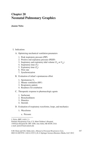
A. Pressure–Volume (P–V) loop (Fig. 20.12)
1. A pressure–volume loop displays the relationship of pressure to volume
(compliance).
2. Pressure is displayed along the horizontal axis and volume is displayed
on the vertical axis.
3. Inspiration is represented by the upsweep from the baseline (PEEP) ter-
minating at PIP and VTI
. Expiration is the downsweep from PIP and VTI
back to baseline.
4. A line drawn from each endpoint represents compliancee (ΔV/ΔP).
Fig. 20.11 Waveforms may be helpful in assessing patient-ventilator interaction (synchrony). If
the infant fights the ventilator (a), inconsistent volume delivery may be present. When the infant
demonstrates synchrony (b) volumes are much more consistent
Fig. 20.12 Pressure–volume loops for both pressure-limited (a) and volume-limited (b) breath
types. Note the inspiratory (Insp) and expiratory (Exp) limbs, origin (PEEP), peak inspiratory pres-
sure (PIP), tidal volume (VT
), and compliance line (Crs) drawn by connecting the origin with the
point of PIP
9. 17520 Neonatal Pulmonary Graphics
5. On a P–V loop, poor compliance is represented by a lower volume in
Pressure control ventilation or an increase in pressure in volume control
ventilation. Recovery from RDS or response to surfactant therapy dem-
onstrates improvement in compliance (Fig. 20.13).
6. Graphic monitoring is useful in identifying appropriateness of pressure
delivery. A “beaking” of the P–V loop often indicates overdistension.
This occurs when pressure continues to rise with minimal change in vol-
ume (Fig. 20.14). Note that the compliance of the last 20% of the P–V
loop is lower than the CD
of the entire loop. This relationship is often
expressed as a mechanics calculation (C20/CD
ratio). A ratio of less than
one usually indicates overdistension. When this is seen, it is appropriate
to evaluate the PIP or VT
and attempt to reduce either of these.
7. P–V loops can help evaluate whether flow delivery from the ventilator is
adequate to meet the needs of the patient. Inadequate flow is represented
by cusping of the inspiratory portion of the curve. Severe flow limitation
may appear as a “figure-eight” on the P-V loop (Fig. 20.15).
B. Flow–volume ( −V V ) loop (Fig. 20.16)
1. A −V V loop displays the relationship between volume and flow. Volume
is plotted on the horizontal axis and flow is plotted on the vertical axis.
2. In this example of a −V V loop (may vary with monitor type), the breath
starts at the zero axis and moves downward and to the left on inspiration,
terminating at the delivered inspiratory volume and upward, to the right,
back to zero on expiration. Note the constant flow delivered with a vol-
ume breath type yields a square inspiratory pattern (a) vs. decelerating
inspiratory flow (b) with a pressure breath type.
3. The −V V loop is useful in evaluating airway dynamics. During con-
ditions of high airway resistance, peak flow is lower for a given volume.
15
10
5
-20 0 20 40
Paw (cmH2O) - Vt (mL)
A
B
Fig. 20.13 On these pressure
volume loops, note the
change in compliance that
occurred with surfactant
delivery. PV loop A was
obtained presurfactant and
shows a much lower volume
and PV loop B was
postsurfactant with an
increased volume. Both
breaths were delivered with
the same pressure
10. 176 J. Nicks
Fig. 20.14 In pressure–volume monitoring, a pressure change should result in a linear change
from the low volume shown in a, as seen in b and d. On the loop in c, however, the last third of the
curve is flattened, indicating that pressure continues to be delivered with only a minimal increase
in volume. This is a sign of overdistention. (From Nicks JJ: Graphics Monitoring in the Neonatal
Intensive Care Unit. Palm Springs, CA, Bird Products, 1995, with permission)
15
Paw (cmH20) - Vt (mL)
10
5
-20 0 20 40
Fig. 20.15 Flow–volume loop displaying inadequate flow, with cusping of the inspiratory portion
of the loop. This figure-eight loop indicates flow starvation
11. 17720 Neonatal Pulmonary Graphics
Typically, expiratory resistance is higher with airway collapse or
bronchospasm.
4. Conditions in the newborn that often result in increased expiratory resis-
tance from airway obstruction include meconium aspiration syndrome
(MAS) and bronchopulmonary dysplasia (BPD) (Fig. 20.17).
Fig. 20.16 Flow–volume loops. (a) Inspiratory flow limitation is demonstrated by flattening of
the loop. The peak inspiratory flow rate (PIFR) is lower for a given volume. (b) Decreasing the
resistance (such as by using a bronchodilator) results in improved (PIFR) and a more normal
appearance of the inspiratory flow–volume loop
Fig. 20.17 Flow–volume and pressure volume loops displaying high airway resistance on expira-
tion. Notice the low expiratory peak flow on the flow–volume loop, in comparison to the inspira-
tory flow. Also note the bowing out on the expiratory side of the pressure–volume loop, which also
illustrates high expiratory resistance
12. 178 J. Nicks
5. The −V V loop is useful for evaluating the effectiveness of bronchodi-
lators in treating airway reactivity. In Fig. 20.18, increased expiratory
flow is seen in the loop on the right compared to the loop on the left.
6. The presence of secretions or water in the ventilator tubing or flow sen-
sor can be seen on the loop displays. Since suctioning should only be
Fig. 20.18 Another example of evaluating a treatment using pulmonary graphics: (a) flow–
volume loop before administration of a bronchodilator; (b) the same loop following treatment.
Note the marked improvement in inspiratory and expiratory flow rates in this patient. (From Nicks
JJ: Graphics Monitoring in the Neonatal Intensive Care Unit. Palm Springs, CA, Bird Products,
1995, with permission)
2
1
0
5 10
Vt (mL) - Flow (L/min)
15
-1
-2
Fig. 20.19 Flow–volume loop on an infant in need of suctioning
13. 17920 Neonatal Pulmonary Graphics
performed as indicated, loops are a useful way to evaluate need for suc-
tioning or draining water from circuit (Fig. 20.19).
V. Dynamics measurements/calculations
A. Tidal volume is measured on inspiration and expiration. Normal delivered
VT
is 4–8 mL/kg.
B. Minute ventilation is the product of VT
and respiratory rate. The normal
range is 240–360 mL/kg/min.
C. Pressure may be measured as peak inspiratory pressure (PIP) or static pres-
sure. Static pressure is obtained by doing an inflation hold maneuver, which
measures pressure obtained by closing the exhalation valve and stopping
flow delivery during a mechanical breath.
D. Compliance is the relationship between a change in volume and a change in
pressure.
1. Dynamic compliance (CD
) is the measurement of compliance based on
peak pressure.
=
−
Ti
D
PIP PEEP
V
C
2. Static compliance is the measurement based on static pressure
=
−
Ti
ST
ST PEEP
V
C
P
3. C20/CD
is the ratio of compliance of the last 20% of the P–V curve to the
compliance of the entire curve. With overdistension, this ratio will be
less than 1.0.
E. Resistance is the relationship of pressure to flow. The pressure may be
dynamic or static, and flow measurements are taken from various
measurements.
1. Peak flow is the maximum flow on either inspiration or expiration.
2. Average flow is based on multiple point linear regression.
3. Mid-volume flow is based on the flow measured at a point of mid-volume
delivery.
−
AW 2
PIP PEEP
(cm H O/L/s) =
Flow
R
Suggested Reading
Cannon ML, Cornell J, Trip-Hamel D, et al. Tidal volumes for ventilated infants should be deter-
mined with a pneumotachometer placed at the endotracheal tube. Am J Respir Crit Care Med.
2000;62:2109–12.
14. 180 J. Nicks
Cunningham MD, Wood BR. Monitoring of pulmonary function. In: Goldsmith JP, Karotkin
EH, editors. Assisted ventilation of the neonate. 3rd ed. Philadelphia: W.B. Saunders Co.; 1996.
p. 273–89.
Donn SM, editor. Neonatal and pediatric pulmonary graphics: principles and clinical applications.
Armonk, NY: Futura Publishing Co.; 1998.
Nicks JJ. Graphics monitoring in the neonatal intensive care unit: maximizing the effectiveness of
mechanical ventilation. Palm Springs, CA: Bird Products Corp; 1995.
Sinha SK, Nicks JJ, Donn SM. Graphic analysis of pulmonary mechanics in neonates receiving
assisted ventilation. Arch Dis Child. 1996;75:F213–8.
Wilson BG, Cheifetz IM, Meliones JN. Mechanical ventilation in infants and children with the use
of airway graphics. Palm Springs, CA: Bird Products Corp; 1995.