1. Stress Concentration Test
1. Group Info
Group 2 MSE 527L
Rna Waheb
Siddhesh Sawant
Dhaval Prajapati
Pavan Kumar Nanne
Ryan Oh
Rameen Hassanzadeh
2. Abstract
Three sample plates of 7075 Aluminum with intentional defects (center hole, U-notches, and V-
notches) were measured and tested under tension in order to determine their stress concentration
characteristics (K) compared to a reference sample (same material, similar cross-sectional area, no
intentional defects). Using the literature to calculate K found all samples to have similar K, with the
Hole sample to have the lowest concentration of stress at K=2.25, and the U-notch and V-notch
samples to be very similar, with K=2.60 and K=2.58 respectively.
3. Procedure
Four samples of 7075 Aluminum were carefully measured and tested under tension in order to
compare their theoretical Stress Concentration Factor (K) to experimental findings. Three of the
samples were intentionally shaped to give different points where stress can accumulate under load—
one with a circular hole in the center, one with two U shaped notches in the sides of the sample, and the
last with V shaped notches (referred to in this paper as “Hole,” “Unotch,” and “Vnotch,” respectively).
The last sample was designed for symmetric stress under load (ie: no intentional defects), but with
similar cross-sectional area to the other samples. This sample was used for reference, giving a standard
with symmetric stress to compare the other samples to. The stress-strain behavior of the samples under
tension is shown in section 4.
4. Results and Discussion
Stress concentration theory states that, under load, the stress of an defected object is not
uniform. The stress instead accumulates at a point in the object, subject to the geometry of the defect.
The maximum stress at the accumulation point is given by the following formula:
σMax=K σNom
Here, σMax is the stress at the accumulation point of the object, σNom is the symmetric, average
stress that the object would be under if it were not defected (but had the same cross sectional area), and
K is the Stress Concentration Factor. This factor is dependent on the geometry of the defects of the
samples, and a theoretical K can be calculated by knowing the type and key dimensions of the defect(s)
in the samples. Table 1 shows the K's for each sample calculated from their dimensions.
In the case for the Hole sample, K depends on the relative size of the hole—it's diameter
relative to total width1
. For our sample, this ratio was found to be ~1:3. Cross checking this value
against a reference table1
showed K ~2.25, implying that the stress under load at the defect edge would
be 2.25 times greater than that of the reference.
The methods for calculating K for the Unotch and Vnotch samples is covered in detail in
sections 5-2 and 5-3. Since stress for the reference sample is uniform across the cross-section, K=1.
2. Sample Hole Vnotch Unotch Reference
Theoretical K 2.25 2.58 2.60 1.00
Table 1: Theoretical Values for K calculated from sample defect dimensions
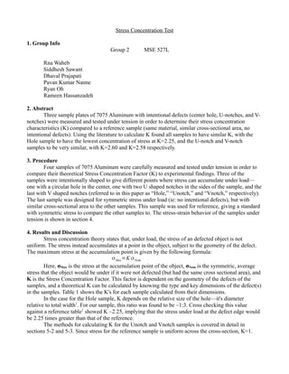
In order to determine K values from experimental data, the stress-strain characteristics of the
samples was used. Figures 1, 2, 3 and 4 show the stress-strain curves of the 4 samples under tension.
Figure 1: Stress-Strain of Hole Sample
4. 5. Appendix
1. Theoretical K for Hole sample:
1. A hole diameter to sample width ratio was determined to be 0.334. Using this reference
table1
, K is shown to be ~2.25.
Figure 4: Stress-Strain of Reference Sample
5. 2. Theoretical K for Unotch
1. K for symmetric Unotch defects in the sides of a plate sample can be calculated from its
dimensions of defect radius, and plate width. The Taylor Expansion used to the third
order is as follows2
:
K =C1+C2(
2t
H
)+C3(
2t
H
)
2
+C4(
2t
H
)
3
In this formula, t is the length that the U notch penetrates into the plate and H is plate width. The Taylor
coefficents are as follows:
C1=0.955+2.169
√(
t
r
)−.081(
t
r
)
C2=−1.557−4.046
√(
t
r
)+1.0321(
t
r
)
C3=4.013+0.424
√(
t
r
)−.0748(
t
r
)
C4=−2.461+1.538
√(
t
r
)−.236(
t
r
)
Here, r is the radius of the U notch.
3. Theoretical K for Vnotch
1. For samples with symmetric V-notch defect located on sides of the plate, K depends on
6. the angle of the V only if that angle is sufficiently large2
. If the angle is <90°, K can be
approximated using the same methodology as the U notch (section 5-2). In this method,
r is the “radius of the triangle,” or the shortest length from the triangle center to its edge.
For our Vnotch sample, this angel was found to be ~48°, significantly less than 90°.
Using the newly defined r, the calculation is then otherwise the same as in 5-2.
6. References
1. "Stress Concentration." http://www.ux.uis.no/~hirpa/KdB/ME/stressconc.pdf
2. Noda and Takase. Fatigue & Fracture of Engineering Materials and Structures.1999
7. the angle of the V only if that angle is sufficiently large2
. If the angle is <90°, K can be
approximated using the same methodology as the U notch (section 5-2). In this method,
r is the “radius of the triangle,” or the shortest length from the triangle center to its edge.
For our Vnotch sample, this angel was found to be ~48°, significantly less than 90°.
Using the newly defined r, the calculation is then otherwise the same as in 5-2.
6. References
1. "Stress Concentration." http://www.ux.uis.no/~hirpa/KdB/ME/stressconc.pdf
2. Noda and Takase. Fatigue & Fracture of Engineering Materials and Structures.1999