SlideShare a Scribd company logo
1 of 48
1
DESIGN, ANALYSIS & FABRICATION
OF
E-BIKE
PROJECT REPORT
SUBMITTED OF PARTIAL FULFILLMENT OF REQUIREMENT FOR THE
AWARD OF THE DEGREE
BACHELOR OF TECHNOLOGY
(MECHANICAL ENGINEERING)
Submitted by
SHIVAM SHUKLA(1642240116)
SRIJIT DWIVEDI(1742240911)
ANAND YADAV (1642240018)
KRISHNA YADAV(1642240061)
IMRAN AHMAD (1642240052)
MAY 2020
2019-2020
BANSAL INSTITUTE OF ENGINEERING AND TECHNOLOGY, LUCKNOW
Dr. A.P.J. ABDUL KALAM TECHNICAL UNIVERSITY, LUCKNOW
1
DESIGN, ANALYSIS & FABRICATION
OF
E-BIKE
PROJECT REPORT
SUBMITTED OF PARTIAL FULFILLMENT OF REQUIREMENT FOR THE
AWARD OF THE DEGREE
BACHELOR OF TECHNOLOGY
(MECHANICAL ENGINEERING)
Submitted by
SHIVAM SHUKLA(1642240116)
SRIJIT DWIVEDI(1742242911)
ANAND YADAV (1642240018)
KRISHNA YADAV (1642240061)
IMRAN AHMAD (1642240052)
BANSAL INSTITUTE OF ENGINEERING AND TECHNOLOGY,
LUCKNOW
MAY 2020
2019-2020
BANSAL INSTITUTE OF ENGINEERING AND TECHNOLOGY, LUCKNOW
Dr. A.P.J. ABDUL KALAM TECHNICAL UNIVERSITY, LUCKNOW
BANSAL INSTITUTE OF ENGINEERING AND TECHNOLOGY,
LUCKNOW
2
CANDIDATE'S DECLARATION
I hereby certify that the work which is being presented in the project report entitled
“E-BIKE ” by “SHIVAM SHUKLA” in partial fulfillment of requirements for the
award of degree of B.tech (ME) submitted in the Department of ME at under “BANSAL
INSTITUTE OF ENGINEERING AND TECHNOLOGY, LUCKNOW” AKTU,
LUCKNOW, is an authentic record of my own work carried out during a period from
JANUARY 2020 to MAY 2020 under the supervision of Mr. ADARSH PATEL.
Signature of the Student
This is to certify that the above statement made by the candidate is correct to the best
of my/our knowledge.
Signature of the SUPERVISOR (S)
The B.tech Viva –Voice Examination of SHIVAM SHUKLA has been held
on ____________ and accepted.
Signature of Supervisor(s) Signature of External Examiner
Signature of H.O.D.
ABSTRACT
3
During the revolution for the eco-friendly technologies bicycles were the most depended modes
of transportation, along with this the consideration of the increase in fuel price and the
environmental factors we must admit that it is far more better to use a bicycle over a motor
vehicle for short distance travelling. Imagine how useful would the bicycle be if even the small
effort applied by man for climbing slopes and riding on rough terrain is reduced in it. We
thought the same way to develop the basics of our project “The e-Bike”. The unit developed by
us is a combination of the standard geared bicycle with an electric power motor cum alternator
that would assist the rider throughout his journey. The system is modified in such a way that
the rider can make choice of which mode he prefers i.e. he can either choose the bicycle to be
driven completely with the electric motor or he can choose it to be driven manually by himself.
The idea of mounting the motor cum alternator assembly onto a geared bicycle was to reduce
the effort to-be applied for extra little weight that the rider will have to take along with the
bicycle. Detailed study about the gross weight has been mentioned inside the report. The unit
has been designed in such a way that people of any age group can depend on it. Our idea of
implementation of the project was mainly biased towards providing inter college transportation
system and to reduce the use of automobiles inside the as a tribute to the “GREEN ENERGY”.
KEYWORDS:Hybrid bicycle; PMDC motor cum alternator; flywheel; multi-crank
freewheel; sprockets; base plates.
4
LIST OF FIGURE
FIGURE NO. FIGURE NAME PAGE.NO.
01. DC MOTOR 10
02. BATTERY 11
03. CHAIN DRIVE 12
04. BRAKING SYSTEM 12
05. VARIOUS TYPE OF SPROCKETS 13
06. E-BIKE FAST DIAGRAM 14
07. HOUSE OF QUALITY ANALYSIS 15
08. MOTOR DECISION MATRIX 16
09. E-BIKE PARTS & ACCESSORIES 18
10. (a) PMDC MOTOR (CROSS-SECTION) 21
(b) PMDC MOTOR (CROSS-SECTION)
11. FLY WHEEL CAD DRAWING 21
12. CAD DRAWING OF MULTI CRANCK 22
FREEWHEEL
13. (A) CAD DESIGN OF SPROCKETS 23-24
(B) CAD DRAWING OF SPROCKETS
14. CIRCUIT DIAGRAM & 25
ELECTRICAL CONNECTIONS
15. PROTOTYPE 26
16. EVOLUTION OF SCIENTIFIC PRODUCTION IN 28
RELATION TO THE ELECTRIC BICYCLE
5
17. TYPES OF SCIENTIFIC PRODUCTION 29
REFERRED TO THE ELECTRIC BICYCLE
18. DISTRIBUTION BY THEMATIC CATEGORY OF 29
SCIENTIFIC PRODUCTION IN RELATION TO
ELECTRIC BICYCLE
19. GEOGRPHIC DISTRIBUTION BY COUNTRIES OF 30
SCIENTIFIC PRODUCTION IN RELATION TO
ELECTRIC BICYCLES
20. CLOUD WORD OF THE WHOLE KEYWORDS 31
RELATED TO ELECTRIC BICYCLE
21. MAIN KEYWORDS USED BY THE COMMUNITIES 33
DETECTED IN THE TOPIC ELECTRIC BICYCLE
22. ELECTRIC BICYCLE KEYWORDS NETWORK & 33
THIER COMMUNITY DETECTION
23. AUTOMOTIVE ALTERNATOR 37
24. WYE CONNECTION STAR & DELTA 38
25. P-CHANNEL & N-CHANNEL MOSFETS 39
26. BATTERY CONNECTIONS 40
27. THOTTLE 41
6
ACKNOWLEDGEMENT
I would like to place on record my deep sense of gratitude to Mr. ADARSH PATEL Dept. of
Mechanical Engineering, B.I.E.T, Lucknow, India for his generous guidance help and useful
suggestions.
I express my sincere gratitude to Mr. ADARSH PATEL, HOD in Department of Mechanical
Engineering B.I.E.T, Lucknow, for his stimulating guidance, continuous encouragement and
supervision throughout the course of present work.
I also wish to extend my thanks to Mr. VIMAL VISHWAKARMA for their insightful
comments and constructive suggestions to improve the quality to the research work.
I am extremely thankful to Prof. S.K AGRAWAL Group Director, B.I.E.T lucknow for
providing me infrastructural facilities to work in without which this work would not have been
possible.
Name of Student-
SHIVAM SHUKLA (1642240116)
SRIJIT DWIVEDI (1742240911)
KRISHNA YADAV (1642240061)
ANAND YADAV (1642240018)
IMRAN AHMAD (1642240052)
7
CONTENTS
PAGE NO.
Candidates declaration...............................................................................................................02.
Abstract......................................................................................................................................03.
List of figure..........................................................................................................................04-05.
Acknowledgement.....................................................................................................................06.
Chapter 1 : INTRODUCTION.....................................................................09-13.
1.1 Principle
1.2 Working medium
1.3 Operation
1.4 Components of E-bike
1.4.1 Dc motor
1.4.2 Platform
1.4.3 Battery
1.4.4 Chain drive
1.4.5 Braking system
1.4.6 Sprockets
Chapter 2 : STRATEGIC GOALS AND DESIGN REQUIREMENTS..14-18.
2.1 Customer Requirements Analysis
2.2 Budget…
2.3 Initial Project Management Plan
Chapter 3 : DESIGN AND IMPLEMENTATION OF E-BIKE..............19-27.
3.1 Hybrid systems
3.1.1 Basic components
3.2 Electrical system design
3.2.1 Electrical connections
3.3 Calculations
3.4 Working of prototype
Chapter 4 : PRODUCTION.........................................................................28-33.
4.1 Evolution of Scientific Production
4.2 Types of Publications and Thematic Categories
4.3 Distribution of Publications by Countries and Institutions
4.4 Keyword Analysis
4.5 Analysis of the Interconnection between Keywords: Community Detection
8
Chapter 5 : DESIGN OF ELECTRIC BIKE.............................................34-37.
5.1 Design of shaft
5.2 Design of sprocket and chain for electric bike
5.3 Calculations of factor of safety
5.4 Advantages
5.5 Disadvantages
Chapter 6 : TECHNICAL DISCRIPTION................................................37-42.
6.1 HARDWARE DESIGN
6.1.1 Automotive Alternator
6.1.2 MOSFETs Connections
6.1.3 Battery Connections
6.1.4 Throttle
6.2 CONTRIBUTION OF TEAM MEMBERS
RESULT AND DISCUSSION..........................................................................43.
CONCLUSION...................................................................................................44.
Appendix 1-Technical Roles, Responsibilities, and Work Accomplished.........................45-46.
Appendix 2- References..........................................................................................................47.
9
Chapter-1
Introduction and Background
Energy crisis is one of the major concerns in today’s world due to fast depleting resources of
petrol, diesel and natural gas. In combination with this, environmental decay is an additional
factor which is contributing to the depletion of resources which is an alarming notification. Our
paper proposes the solution for this above perilous problems. The system which we innovated
is the Electric Bike. This project has various benefits both to the members of the team and also
external benefits thereby making awareness of using alternative modes of transport. The
Electric Bike which works on the battery that is powered by the motor is the general mode of
transport for a local trip. The solar panels can be alternative source for this by adding it to the
system. The Electric bike which will be running on battery, the power is supplied by the motor,
thereby supplying this power to drive the other gear components. The main purpose of using
this E-bike is that it is user friendly, economical and relatively cheap. The efficiency of this
system undeniable compared to conventional modes of transport. The following table shows
the specification of various electric bikes used in few countries:
Table 1 Specifications of E-Bike in various countries
Country
Type of
bike
Speed
limit
in km/hr
Watt
Weight in
kgs
Age required
in yrs
Australia Pedal 25 250 None None
Canada Hand 32 500 None Various
China P/H 30 200 20 None
Norway Pedal 25 250 None None
Israel Pedal 25 250 30 14
UK Hand 27 250 40 14
Taiwan Hand 25 200 None None
US Hand 25 750 None None
China P/H 30 500 None None
1.1What is Electric Bike?
The Electric bike is a bike which is driven with the help of battery which is coupled to
electric motor.
Main principle: It works on the principle that the electromotive force of an A.C. motor
which receives electrical energy stored in D.C. battery is converted with the help of D.C. to
A.C. converter.
Working medium: Here for the motivation of prime mover the chemical reaction takes
place from which an energizing current is evolved which is responsible for the working.
1.2 The working medium is sulphuric acid which is separated into columns of H ions and
negative SO4 ions. When mixed with water. If the poles of the cell are connected by a load, the
flow of the electrons is from negative to positive. A bivalent positive lead is produced from
neutral lead when combined with bivalent negative of SO4 group to form lead sulphate. This
results due to scarcity of electrons at negative pole. Through the electron supply a bivalent
10
positive lead is produced at positive pole from quadric valent positive lead. A combination of
SO4 comes into existence thereby ruling the combination of O2 which leads to formation of
PbSO4. The atoms of oxygen and hydrogen from electrolyte are released together to form water
thereby decreasing the density of battery acid.
1.3-Operation:In this a DC waveform which is obtained id made sinusoidal due to
operational transistorized D.C. to A.C. amplifying circuit by switching the electric energy
in the form of electric current which flows from battery to D.C. to A.C. converter circuit.
By using amplifier circuit the small A.C. current is amplified again. In order to drive the
circuit through the condenser, this amplified current is fed to the stator winding of the A.C.
motor. The condenser which is used acts as a storage of electric energy and delivers at the
time of requirement. The sprocket wheel installed on motor shaft is driven by the motive
power of the electric energy.
The rear sprocket wheel is being rotated by the chain drive mechanism on which the other
two remaining sprocket wheels are installed. The wheel is driven by the rear wheel
installed on the rear sprocket. Thus the electric bike is mobilized by using electric power.
 COMPONENTS OF E – BIKE
The Electric bike consists of following components which are DC motor, Frame, Platform,
Battery, Drive etc. (Barve, Design and Development of Solar Hybrid Bicycle, 2016)
1. Dc motor: The motor is having 250 watt. Capacity with maximum 2100 rpm. Its
specifications are as follows:
Current Rating: 7.5amp
Voltage Rating: 48 Volts
Cooling: Air – cooled
Bearing: Single row ball
11
FIGURE-1 : DC MOTOR
2. Frame: The Frame is made up of M.S. along with some additional light weight
components. The frame is designed to sustain the weight of the person driving the unit, the
weight of load to be conveyed and also to hold the accessories like motor. Also it should
be design to bear and overcome the stresses which may arise able to due to different
driving and braking torques and impact loading across the obstacles. It is drilled and
tapped enough to hold the support plates.
3. Platform: The Platform is designed with robust base so that it can hold the load along
with the weight of the driving person uniformly. It is fabricated from Mild Steel at a
specific angle in cross section and welded with a sheet of metal of specific thickness. The
platform’s alignment is kept horizontal irrespective whether it is loaded or unloaded and
this is directly bolted and welded to the frame.
4. Battery: The battery also acts as a condenser in a way that it stores the electrical energy
produced by the generator due to electrochemical transformation and supply it on demand.
Battery is also known as an accumulator of electric charge. This happens usually while
starting the system.
12
FIGURE-2 : BATTERY
5. Chain Drive: A Chain is an array of links held together with each other with the help of
steel pins. This type of arrangement makes a chain more enduring, long lasting and better way
of transmitting rotary motion from one gear to another.
FIGURE-3 : CHAIN DRIVE
The major advantage of chain drive over traditional gear is that, the chain drive can
transmit rotary motion with the help of two gears and a chain over a distance whereas in
traditional many gears must be arranged in a mesh in order to transmit motion.
6. Braking System: For the braking system it is convenient to use braking system used in band
brake system which consist of spring loaded friction- shoe mechanism, which driven with the
help of hand leaver
FIGURE-4 : BRAKING SYSTEM
13
7. Sprockets: The chain with engaging with the sprocket converts rotational power in to rotary
power and vice versa. The sprocket which looks like a gear may differ in three aspects:
 Sprockets have many engaging teeth but gears have only one or two.
 The teeth of a gear touch and slip against each other but there is basically no slip page in case of
sprocket.
 The shape of the teeth are different in gears and sprockets.
(Barve, Design and Development of Solar Hybrid Bicycle, March 2016)
FIGURE-5 : VARIOUS TYPES OF SPROCKETS
14
Chapter-2
Strategic Goals and Design Requirement
2.1 Customer Requirements Analysis
The first step taken during the product planning phase was the analysis and evaluation of the
project requirements given by the customer or sponsor. To effectively plan goals and an
efficient critical path, a design proposal needed to be identified quickly. The first step in
understanding the sponsor’s requirements was to set up an interview to discuss how the design
has the potential to positively impact society and to discuss design goals. My Team learned that
the most important goal was the ability to make the design as inexpensive as possible.
Other important goals were to maximize efficiency and power consumption by pulsing the
rotor and stator coils, achieve a wide range of speeds, increase the torque at low speeds, and
implement regenerative braking. In order to understand and implement a design that met all of
the requirements, multiple analysis techniques were performed. One technique was the
development of a FAST diagram in order to understand and define the product functionality
and the scope of the project. Figure 6 below is the our team FAST diagram.
FIGURE-6 : E-BIKE FAST DIAGRAM
15
The basic function of the design is to use the alternator to control the electric vehicle’s
speed. This is done by either speeding up or slowing down the alternator. In order to
speed up the alternator, the throttle needs to be applied. In order to speed up the alternator
shaft, current needs to be applied to the stator and rotor at the quadrature angles. This is
done using the microcontroller and the software logic to switch the MOSFETs that are
connected to the stator and the rotor. In order to slow down the electric vehicle, the brake
lever needs to be applied. Slowing down the alternator is achieved by slowing down the
alternator shaft. This is done using regenerative braking. Regenerative braking is executed by
drawing current from the alternator to charge the battery that is supplying the circuit and the
alternator. This can be done by controlling the field using the microcontroller and the software.
Another technique that was utilized was the House of Quality analysis technique. This
analysis method proved to be quite useful because it helped our Team understand the
Critical Customer Requirements for the design. This helped prioritize the project needs and
gave direction for which specifications to look for when selecting
components. The House of Quality Matrix is shown in Fig.7
FIGURE-7 : HOUSE OF QUALITY ANALYSIS
16
This type of analysis was very helpful because it was a tool used to assist in data based
decision making. It also helped to reduce design uncertainty because by understanding the
customer requirements and how the quality characteristics or measures affect them. It
was easy to clarify how the data collected would help determine a best approach. It was
also a good tool to determine which measurements would prove to be of higher
importance for selecting a design that best matches all of the specifications. From the
House of Quality, it was determined that efficiency and speed were the easiest customer
requirements to analyze using the quality characteristics. One of the harder requirements
to measure was the reliability. It was also noticeable that high output power and power
dissipation had a strong inverse relationship because the more output power of the
alternator that is measured, the lower the power loss or dissipation. Some of the other
strong positive relationships as seen in the house of quality were high rpm and current
draw, high current draw and output power, and high output power and high torque.
Another useful piece of this type of analysis was being able to prioritize customer
requirements. The most important customer requirements for this design were cost,
efficiency, speed, and reliability.
Once the main project goals were prioritized, project design functionality planning could
begin. To make critical design component selections, decision matrices were developed
which allowed for the comparison of different options in relation to the established
design goals and sponsor requirements. The first major decision encountered was the type
of motor to be used with the prototype. From the motor decision matrix in Figure 8, an
automotive alternator clearly met the goals for the project over other available options, an
AC motor or a brushless DC motor. As can be seen from the decision matrix below, the
alternator is significantly better than its counterparts with regards to cost and speed.
FIGURE-8 : MOTOR DECISION MATRIX
17
2.2 Budget
One of the key constraints of this project was developing a design that is both cost
effective and efficient. The most expensive portion of the project are the automotive
alternators, which cost around 1400 to 2100rs. The use of these alternators instead of
brushless DC motors will save at least 4200rs per motor. Like most of the parts that are
required for this project, the automotive alternators were already provided to the team;
therefore the cost is not tracked in the 35000rs budget, but will be included in the cost per
unit budget.
Additional parts that were needed include the diametrically magnetized
magnet, the AMS AS5132 rotary sensor, the P -channel and N-channel power MOSFETs,
terminal blocks, power recovery diodes, and an external throttle. Other hardware circuit
components such as colour coded resistors, NPN and PNP transistors, Zener diodes,
capacitors, heat sinks, and header pin connectors that were required for the MOSFET
switching PCB were not included in the budget since they were obtained from the ECE
shop at no cost. These circuit items were included in the cost per unit budget.
In order to have the opportunity to implement design changes throughout the design
process, extra components were ordered just in case components were damaged during
testing. The table below shows the cost of all of the components ordered by my team
throughout the design process. The total prototype design cost was 23277.8, which is
within the 35000 budget for the semester.
The cost of the PCB fabrication, 10 AWG wiring used for the stator coils and battery
connections, two 12V batteries, and all other hardware components mentioned above. This is
because these components were obtained from the sponsor or from the ECE shop. A majority
of the prototype design costs were shipping costs. For example, the shipping cost for 26.6rs
magnets was greater than the product cost. For the per unit production cost, the cost was
calculated without the shipping costs of the parts. A per unit production cost was also
calculated below to show the cost to make one prototype E-bike motor and controller.
It is easy to see that the cost of one production unit is significantly lower than the cost to
make the prototype design. This is due to the fact that additional components were
ordered even though not all of them were necessary. For future production, terminal
blocks like those used in the prototype design will not be necessary for attachment to the PCB
from the stator coils. Prices for components such as the AMS sensor, recovery
power rectifier, P-channel and N-channel MOSFETs, 10 AWG wire are much cheaper if
bought in bulk quantity. For a production setting, all of these components will be
purchased in bulk.
18
2.3 Initial Project Management Plan
The initial project timeline consisted of seven main phases. These phases include project
definition, research of new designs, development of conceptual designs, initial prototype
preparation, initial testing, initial prototype construction, and final design construction.
The project schedule and project timing was organized the seven main phases, which were
further broken down into tasks. These tasks consisted of a start date and an end date. The
project schedule consisted of a critical path. Tasks on the critical path could not be started
unless the task before was completed. These tasks were the most critical to the project because
any delay caused a delay to the whole project. It was important to try to shift the critical path.
For the most part, The only modification came near the end of the design process in the
“Construct Final Design” phase. Since the team decided to go with one PCB design, the
“design PCB layout” and “PCB fabrication/soldering” tasks were moved to the “Construct
Initial Prototype” phase. The project prototype and final design were very similar, and the PCB
was fabricated before testing efficiency. This was because in order to run and test the high
current portion of the circuit, a PCB needed to be fabricated. A breadboard could not be used
for these tests.
FIGURE-9 : E-BIKE PARTS AND ACCESSORIES
19
Chapter-3
Design and Implementation of E-Bike
Global warming and scarcity of traditional resources are becoming major problems in the
current scenario. Due to the economic challenges India is facing in automotive sector the
hybrid bicycle market has a huge growth potential. People try to move towards "clean"
energies. These facts among others will leverage the electric bicycle industry on the top of the
agendas not only in India. Moreover the vision of an electric engine, which supports the
muscular strength, became reality. Bicycles with such a supporting electric engine belong to the
innovative vehicles, which are wholeheartedly suitable for everyday life. In face of continuous
climate discussions and permanent traffic jams, electric bikes have the potential of solving such
issues and making a more energy efficient and environment friendly mobility possible.
Accordingly a continuous trend towards electric bicycles can be expected simultaneously in
whole of India. So it becomes very necessary to manufacture the electric cycles so cheaply that
the common people in our country can afford to buy it. The currently existing electric scooters
are far more costly and due to budgetary constraints a middle class person cannot afford such a
locomotive at his place. Along with the development of technologies the theory must be also
implemented to design and manufacture a product that can be sold off at a greater frequency,
which has a very low production cost and one that is of good quality. In order to implement all
the above ideas, we planned to make the design and product in such a manner that it can be
completed with the existing “E-Bikes” in the market.
A. Background
The basic idea is to attach a motor to the cycle for its motion. A motor that is powered by a
battery and that can be switched on during difficult terrains and switched off and pedal to get
the battery re-charged during motion in a flat terrain. The idea came into our mind as different
stages of project planning, firstly we wanted to implement a simple moving system so the
projection of cycle as a system came into our mind, and second stage was adding a necessarily
useful component into it that can be beneficial in the future and for common people, falling into
the current trend was that of hybrid system so we ended up planning to assemble a motor unit
into the cycle drive. There were many issues that came up while making such a system major
one of them being the power of the motor to be used, since no such previous systems were
made we could not predict the type of motor which we should go for. Second thing being the
weight factor, the addition of extra weight on to the system, which can cause discomfort to the
rider while normal pedalling. Third was the type of battery to be used, we should go for a
battery that has longer life, economically viable, and also has less maintenance issues. Fourth
issue was that self-recharging a battery with a motor alternator unit that too with the simple
cranking motion of the cycle was not viable, we had to utilize a mechanism that can come in
handy here and that was by using the flywheel rotation technique.
20
B. MechanicalDesignandSystem Integration
The main aim was to fabricate a prototype that would be very light and comfortable for
the rider to handle . As the motor and other drive components would take in most of the
free space in the system our design challenge was to make the motor-alternator unit as a
single system. This was our major challenge, for this purpose we developed the motor
cum alternator at its minimum possible size and also at the lowest possible cost.
Mounting the battery was another challenge, the location of the mounting could have
been anywhere in the rest of the space available near the motor or we could have used
up the empty space near the carrier. Keeping in mind the comfort of the rider the battery
casing was mounted behind the rider, near the carrier location. Looking at the
complicated arrangement of the system one may easily think that the drive
arrangement could have been completed in a single step i.e. the direct link from the
motor to the drive. But the real fact is that this would make the cranking for self-
recharging mechanism difficult, since the speed for alternator recharging cannot be
achieved by simple cranking a flywheel has to be used to store the cranking energy and
thus the rotation and cranking at normal cycling becomes easier.
3.1 HYBRID SYSTEMS
A. Overview
This section of the paper deals with the mechanical design of the system and the
various parts used in the system integration. The power transmission system consists of
the motor , the chain sprockets, flywheel, housing and the rear wheel. However, before
we could select these components, we performed some basic calculations relating
energy transfer through the system. Primarily we focused on the current requirements
of the system, and a number of torque-speed relationships. Both the acceleration on flat
ground and hill climbing ability of the system depend on how much torque can be
delivered by the various system components. Before we could size the batteries, we
needed to estimate when the motor would demand the most current and the duration
that it would draw its peak current. These situations would be at start up (acceleration)
and when climbing a gradient. The main components affected by the following
calculations are the motor and the battery.
B. Components of Hybrid System
1. PMDC MOTOR (Permanent magnet DC motor):
Permanent magnet DC brushed motors (PMDC motors) consist of permanent magnets,
located in the stator, and windings, located in the rotor The ends of the winding coils
are connected to commutator segments that make slipping contact with the stationary
brushes. Brushes are connected to DC-voltage supply across motor terminals. Change
of direction of rotation can be achieved by reversal of voltage polarity. The current
flow through the coils creates magnetic poles in the rotor that interact with permanent
21
magnet poles. In order to keep the torque generation in same direction, the current flow
must be reversed when the rotor north pole passes the stator south pole. For this the
slipping contacts are segmented. This segmented slip ring is called commutator. Figure
3(a) shows angular position just before commutation of rotor winding current and
Figure 3(b) after it.
FIGURE-10 (a): PMDC Motor (Cross-Section)
FIGURE-10 (b): PMDC Motor (Cross-Section)
2. Flywheel:
A flywheel is a rotating mechanical device that is used to store rotational energy. Flywheels
have a significant moment of inertia and thus resist changes in rotational speed. The amount of
energy stored in a flywheel is proportional to the square of its rotational speed. Energy is
transferred to a flywheel by applying torque to it, thereby increasing its rotational speed, and
hence its stored energy . Conversely, a flywheel releases stored energy by applying torque to a
mechanical load, thereby decreasing its rotational speed. Flywheels are typically made of steel
and rotate on conventional bearings; these are generally limited to a revolution rate of a few
thousand RPM. Some modern flywheels are made of carbon fiber materials and employ
magnetic bearings, enabling them to revolve at speeds up to 60,000 RPM. Our design, due to
the simplicity of its application, uses a flywheel which is made up of cast iron having a
diameter of 17cm.Carbon-composite flywheel batteries have recently been manufactured and
are proving to be viable in real-world tests on main stream cars. Shows the CAD drawing of the
flywheel.
FIGURE-11 : FLY WHEEL CAD DRAWING
22
3. Housing:
Housing is used for making an interconnection between the rotating flywheel and the sprocket
at the other end. It is this sprocket from the rotating flywheel connected to a shaft that drives
the multi crank free wheel. The housing is attached with a rubber bush to avoid the shocks.
They are normally used in door hinges for making perpendicular movable connections. The ball
bearing inside the housing chamber allows the free rotation of the connecting shaft inside the
housing.
DesignSpecifications:- Length: 1m; External Diameter: 0.7m; Internal Diameter: 0.5m;
Thread Pitch:0.024m.
4. Multi-crank Freewheel:
Multi crank freewheel is developed as alternate mechanism to drive the rear wheel from the
motor power the crank is developed in such a way that the ball bearing has a special effect
when rotation on one direction through motor happens the ball bearing external lock holds the
moving pedal thus restricting its motion, on the other hand when the rotation with pedal
happens the bearing engages with the pedal and thus the drive through cranking happens. For
developing, the crank was attached with another crank of the same diameter so that there will
not be any difference in the pedaling effect to the rider.
DesignSpecifications:- Crank Diameter: 0.18m; Number of Teeth: 52 the CAD drawing of
multi-crank freewheel.
FIGURE-12 : CAD DRAWING OF MULTI CRANCK FREEWHEEL
23
5. Sprockets:
A sprocket or sprocket-wheel is a profile wheel with teeth, cogs, or even sprockets that mesh
with a chain, track or other perforated or indented material. The name 'sprocket' applies
generally to any wheel upon which are radial projections that engage a chain passing over it. It
is distinguished from a gear in that sprockets are never meshed together directly, and differs
from a pulley in that sprockets have teeth and pulleys are smooth. Sprockets are used in
bicycles, motorcycles, cars, tracked vehicles, and other machinery to transmit rotary motion
between two shafts where gears are unsuitable or to impart linear motion to a track, tape etc.
Perhaps the most common form of sprocket may be found in the bicycle, in which the pedal
shaft carries a large sprocket-wheel, which drives a chain, which, in turn, drives a small
sprocket on the axle of the rear wheel. Early automobiles were also largely driven by sprocket
and chain mechanism, a practice largely copied from bicycles. Sprockets are of various designs,
a maximum of efficiency being claimed for each by its originator. Sprockets typically do not
have a flange. Some sprockets used with timing belts have flanges to keep the timing belt
centered. Sprockets and chains are also used for power transmission from one shaft to another
where slippage is not admissible, sprocket chains being used instead of belts or ropes and
sprocket-wheels instead of pulleys. They can be run at high speed and some forms of chain are
so constructed as to be noiseless even at high speed.
FIGURE-13 (A): CAD DESIGN OF SPROCKETS
24
Sprockets (Front and Side Views)
DesignSpecifications:-
Sprocket 1 (connected with the motor) Number of Teeth: 16; Diameter: 70mm.
Sprocket 2 (connected with housing) Number of Teeth: 16; Diameter: 70mm the CAD drawing
of multi-crank freewheel.
FIGURE-13 (B): CADDRAWING OF SPROCKETS
3.2 ELECTRICAL SYSTEM DESIGN
A. Overview
The PMDC motor had to be regulated by a mechanism which involved a DC motor driver .This
driver had specifications able to withstand up to 20A which was key to this project as varying
loads would undoubtedly draw more current. So the rated current rating had to be high enough
to withstand this. The driver is controlled by an Arduino Board which receives input signals
via. a potentiometer (variable resistance). The Arduino board was programmed in such a way
that varying the resistance in the potentiometer would result in an equivalent value of bytes
which the program could comprehend and translate to proportional DC motor speeds.
25
B. Programming
The programming was done on the software accompanied with the Arduino Board. When the
“initialise motor” command is used charge starts flowing to the motor through the driver. When
the program enters the loop, the potentiometer values (read as resistance pulse values) gets
translated to equivalent bytes that lets the Board allow charge to pass through the motor thus
increasing/decreasing the speed. Once the loop is exited, the program goes back to initial value.
C .ElectricalConnections
There are different approaches to driving a motor when it comes to driving a motor with
Arduino. If a simple relay is used to drive a motor it can only turn the motor on and off. In case
a single transistor like TIP120 (BJT) or IRF510 (MOSFET) is used, it is possible to control the
speed of the rotation. There exist smarter DC motor drivers (so called H-bridge) that can
control the direction of rotation and even brake. An example of such a driver is MC33887
Motor Driver which is affordable and versatile. This driver can control a single DC motor with
maximum consumption of 2.5A and peaks of 5A. Motor voltage can range from 5-28V which
makes it an excellent general purpose motor driver shows the circuit diagram and shows the
electrical connection.
Electrical Connections
Circuit Diagram
FIGURE-14 : CIRCUIT DIAGRAM & ELECTRICAL CONNECTIONS
26
3.3. CALCULATIONS
A. Maximum currentdrawn from the cycles at twostages:-
1. During Acceleration;
2. During Hill Climbing
1. During Acceleration the forces acting on the system are: Drag force; Friction from tires;
Force due to gravity. There is a major change of energy from electrical to K.E+P.E
K.E = ½.m.v2 Where the value of ‘v’ keeps varying.
Electrical energy = V.I.T
Final K.E = voltage rating x current required x time to accelerate
Voltage provided=36v
Maximum mass = 120Kg(value taken is considering mass of man 100 kg+unit wt. 20kg)
K.E = ½ x 120 x (25)2 = 375500 W. (POWER CONSUMED)
375=36 x I x20(s), I=0.52A; 375=36 x Ix 40(s), I=0.26A; 375=36 x Ix 60(s), I=0.17A
[These values shows the current drawn when unit reaches 25Km/hr. at various intervals]
Current drawn from the unit is more when time taken is less and vice versa. Considering that
the cyclist can achieve the25km/hr. mark in 60(s), the current drawn will be 0.17A. But
practically the values varies from person to person hence an average value is calculated to be
about = 0.3166 ≈ 0.32 A.
2. Gradient ascent requirements (During hill climbing) Gradient is given by, SinѲ=ΔH/Δx
Maximum power drawn during hill climbing based on the calculation is 600W; hence the motor
of that rating or more than that rating must be used.
B. Selection of Speed and Gear Reduction
For a desired top speed of 25Km/hr. Gear Ratio = 1:9 (drive: driven)
Speed (motor) = 3100 rev/min x 27p/rev x 60 minutes/hr. x 1ft/12 inches x 1 mi/5280ft = 24.9
KM/Hr.
Desired speed = 25km/hr. Therefore speed of motor/ desired wheel speed = 24.9/25 = 0.996̴0.9
(taking the lower limit).
C. Motor Starting Current
Motor starting current (from dead start) =3.44A.
Motor starting current (cont. motion) =1.05A.
27
3.4 WORKING OF THE PROTOTYPE
The 150 watt PMDC motor which gives a 1000 RPM at 12V and 15A rating was linked with a
flywheel using the sprocket ratio at 16:40 (motor : flywheel) teeth ratio, the shaft from the
flywheel was then linked to the sprocket on the other side with a housing. The drive from this
sprocket to the multi crank freewheel is attached again at 16:52(sprocket: crank freewheel)
teeth ratio. These ratios were selected for maximum efficient power transmission with minimal
loss. The drive from this crank is directly linked with rear wheel sprocket that facilitates its
motion. When the motor is switched ON, the motor draws current from the two dry cell
batteries connected in parallel that would give an effective discharge of 12V and 14A. Since the
motor uses maximum current (11 amp) during starting a battery of that specification was used.
Later on as the effective speed increases the current drawn reduces to 1.77A. Figure shows the
final assembled prototype of the hybrid bicycle.
FIGURE-15 : PROTOTYPE
Final Assembled Prototype
The motion of the motor actuates the flywheel whose rotation in turn drives the shaft through
the housing and make the sprockets at the other end move which would drive the multi crank
and thus the rear wheel. It should be noted that while the motor is in working mode the pedals
won’t rotate which would otherwise cause discomfort to the rider. For this to work we have
added a ball bearing at the crank spot that would disengage the inner ring while motor is in
rotation and engage them when the motor is switched off.
28
Chapter 4
PRODUCTION
4.1. Evolution of Scientific Production
From 1973 to 2017, the search yielded 896 document results, whose temporal distribution is
show in Figure. It must be noted that the search has no data prior to this date, for this reason
1973 is considered the first year of this search. It is observed that the increase begins in 2003,
and 2008 is the year when scientific production increases significantly. These publications are
written mostly in English in more than 90% of cases, although the Chinese language also
appears strongly since 2001,with 7.5%, other languages are already anecdotal with less than 1%
and included Japanese, Dutch, German, Polish, Russian, Spanish, and French.
FIGURE-16 : Evolution of the scientific production in relation to the electric bicycle
(1973-2017)
4.2. Types of Publications and Thematic Categories
In the analysis of the means of scientific diffusion, generally, the most used means are
journal, except in areas of novel research, where the search terms appear mostly in
specialized scientific conferences. This is what occurs in our case, where conference
papers account for the most part, 54% of the total, while articles in journals account for
29
43%. Figure shows the percentage of the types of scientific production distributed on the
theme of electric bicycle.
FIGURE-17 : Types of scientific production referred to the electric bicycle (1973–2017).
The thematic categories in which the scientific work is classified show the approaches from
which the problem under study is approached. In our case, it is observed that the principal
categories are: Engineering (42%), Computer Science (12%), Energy (10%), Social Sciences
(10%), and Medicine (4%).
FIGURE-18 : Distribution by thematic category of scientific production in relation to electric
bicycles
30
4.3. Distribution of Publications by Countries and Institutions
Figure shows the geographical distribution of the countries with publications in this field.
The top ten countries concerned about this issue, as reflected in their scientific
production, are, by order China, United States, Taiwan, Italy, Germany, Japan, South Korea,
Australia, Malaysia, and Canada.
FIGURE-19 : Geographic distribution by countries ofscientific production in relation to electric
bicycles
Table 1 shows that the institutions with more than 8 publications, of the 16 represented, 10 are
from China: Southeast University, Tongji University, Tsinghua University, Zhejiang
University, Southwest Jiaotong University, Beijing JiaotongDaxue, Chang’an University, Jilin
University, Chinese Academy of Sciences, and Nanjing University of Aeronautics and
Astronautics. 2 are from the USA: University of Tennessee, Knoxville and UC Berkeley, while
a number of countries produceone publication and include Italy (Politecnico di Milano),
Australia (Monash University), Taiwan include Italy (Politecnico di Milano), Australia
(Monash University), Taiwan (Kao Yuan University Taiwan), and Portugal (Universidade de
Lisboa). If the total citations (TC) in these publications are observed, the Tsinghua University
leads, followed by the University of Tennessee.
31
4.4. Keyword Analysis
The analysis of the keywords identifies or summarizes the work of the researchers .
This section analyses the keywords obtained from the main query described in the methodology
section. In the overall articles obtained from the query, the frequency of appearance of each
keyword has been obtained. In Figure , a word cloud has been represented where size and
centrality show the importance of that keyword within the total publications, defined by the
highest frequency of occurrence or the number of times it is repeated. If the main query is
filtered by each of the major countries by number of publications, the main keywords of these
countries are obtained. Therefore, the three main keywords of the top ten countries. The
keywords of the countries that least resemble the rest are those of Japan and Australia, and both
have a gender component that is very much present in their studies.
On the other hand, if the main search is limited to a particular keyword, the frequency of
occurrence of this keyword for each year can be obtained. Figure shows the evolution over time
of the top three keywords. Note that the search is limited to the last ten years, from 2007 to
2017. This is due to the small difference existing in earlier years (note that in 2007 two of these
keywords had no values). The keywords “Electric Vehicle” were almost always above the
others but they have emerged mainly since 2015. The other two keywords, “Sporting Goods”
and “Transportation”, were in the same rank until 2012. Since then, sporting goods began to
distance itself upwards. In this part of the analysis, it is worth noting that the electric bicycle is
no longer just an alternative for transportation, but a means of daily sports practice to improve
health. Indeed, the electric bicycle is considered a vehicle. It is important to highlight this fact,
because for many countries it is proposed as a solution to the problem of personal transport. On
the other hand, in the US, “sporting goods” refers to items that are purchased for recreational
purposes.
FIGURE-20 : Cloud word of the whole keywords related to electric bicycle
32
4.5. Analysis of the Interconnection Between Keywords: Community Detection
Considering a community as a system composed by multiple interdependent elements, with
a very wide range of relationships that are variable and dependent, we could accept,
conceptually, that communities are made up of a highly cohesive central core and peripheral
spheres with unions increasingly weaker compared to the center. The central core would be
structured by the most significant elements of the community, in terms of granting a definable
individuality, evinced by the links between its constituents who share the strongest and most
significant connections within the entire community complex. Communities or clusters are
usually groups that are more likely to relate to each other than with members of other groups.
Identifying communities is an interesting problem in our case because it will guide us around
which way the main topics of the publications are grouped. For this specific analysis, we
downloaded the keywords of each publication separately, generating a file line with up to six
keywords used in each publication; this file was entered into a network analysis software that
detected the main communities.
Clusters with different colours have been shown and they are represented in the form of neural
network. Each node is a keyword, and the thickness of the link between nodes is the frequency
of that relationship. In the analysis of the publication of the electric bicycle, six communities
have been detected using a community detection algorithm, and Table 3 shows their main
keywords. To identify each cluster a proposed name is offered in the last column of the table.
By order of importance they are: Transportation–Environment, Electrical engineering, Safety,
Batteries, Sporting goods–Urban planning, and Mechanical engineering. Transport and
environment is the first in order of importance, highlighting this cluster within world research,
and above all the concern for air pollution in cities.
As was expected, electrical engineering supports this technology, and it is quite logical that it
ranks second. The risk factors for accidents have increased greatly with the increase in the
number of electric bicycles, so the issue of safety appears as the third most important issue.
Batteries rank fourth among the clusters, highlighting the improvement of batteries, especially
33
in charging systems and the increase in their autonomy. As mentioned above, it is surprising
that the electric bicycle is part of the concept of sport, but its daily use undoubtedly promotes
individual sport, and this can be a health enhancing sports routine. The mechanical approach is
therefore the last of the categories.
FIGURE-21 : Main keywords used by the communities detected in the topic electric bicycle
FIGURE-22 : Electric bicycle Keywords network and their community detection
34
Chapter 5
DESIGN OF ELECTRIC BIKE
5.1 DESIGNING OF SHAFT
BENDING:
The force which develops across a specific cross section of the shaft, it generates stress at that
point of cross section that are subjected to maximum loading. This internal or resisting moment
gives rise to the stress called as bending stresses.
Torsion: When the shaft which is twisted by the couple such that the axis of that shaft and the
axis of the couple harmonize, that shaft is subjected to pure torsion and the stresses generated at
the point of cross section is torsion or shear stresses.
Combined Bending and Torsion: In actual practice the shaft is subjected to combination of
the above two types of stresses i.e. bending and torsion. The bending stresses may occur due
any one of the following reasons:
1. Weight of belt
2. Pull of belts
3. Eccentric Mounting of shafts/gears
4. Misalignment of shafts/gears
On contrary, the torsional movement occurs due to direct or indirect twisting of the shaft.
Hence at any given point on cross-section of the shaft, the shaft is subjected to both bending
and torsional stresses simultaneously. Following stresses are taken in consideration while
designing the shaft:
Shaft design
T = 36000 N mm
T = 3.14 / 16 x σsx d3
Fs allowable = 80 N/mm2
6820 =3.14 x σsx d3/16
σs= 34.73 N/mm2
Material = C 45 (mild steel)
σ ut= 320 N/mm2 ------------ PSG design data book.
factor of safety = 2
σt= σb= σ ut/ fos
= 320/2
= 160 N/mm2
σs= 0.5 σt
= 0.5 x 160
= 80 N/mm2
σsis less then allowable so our shaft design is safe
35
5.2 Designof Sprocket and Chain for Electric Bike
We know,
TRANSMISSION RATIO = Z2 / Z1 = 66/11 = 6
For the above transmission ratio number of teeth on pinion and the number of teeth sprocket is
in the range of 21 to 10, so we have to select number of teeth on pinion sprocket as 11 teeth.
So, Z1 = 11 teeth
SELECTION OF PITCH OF SPROCKET
The pitch is decided on the basis of RPM of sprocket.
RPM of pinion sprocket is variable in normal condition it is = 2100 rpm
For this rpm value we select pitch of sprocket as 6.35mm from table.
P = 6.35mm
CALCULATION OF MINIMUM CENTER DISTANCE BETWEEN SPROCKETS
THE TRANSMISSION RATIO = Z2 / Z1 = 66/11 = 6 which is less than 7
Dia. of small sprocket,
Periphery = π × dia. Of sprocket
11 × 6.25 = π × D
D = 11 × 6.25 / π
D = 21.8 mm
Dia. of sprocket,
Periphery = π × dia. Of sprocket
66 × 6.25 = π × D
D = 66 × 6.25/ π
D = 131.3 mm
So from table, referred from PSG Design Data book
The minimum centre distance between the two sprocket = C’ + (80 to 150 mm)
Where C’ = Dc1 + Dc2
2C’= 131.3 + 21.8
2C’ = 76.5 mm
MINIMUM CENTER DISTANCE = 76.5 + (30 to 150 mm) MINIMUM CENTER
DISTANCE = 170 mm
CALCULATION OF VALUES OF CONSTANTS K1 K2 K3 K4 K5 K6 – (with
help of PSG DesignData)
Load factor K1 = 1.25 (Load with mild shock)
Distance regulation factor K2 =1.25(Fixed center distance)
Center distance of sprocket factor K3 =0.8
36
Factor for position of sprocket K4 = 1
Lubrication factor K5 = 1.5 (periodic)
Rating factor K6 = 1.0 (single shift)
5.3 CALCULATION OF VALUE OF FACTOR OF SAFETY
For pitch = 6.35 & speed of rotation of small sprocket = 2100 rpm
Factor of Safety for this drive = 8.55
Calculation of Allowable Bearing Stress:
For pitch = 6.35 & speed of rotation of small sprocket = 2100 rpm
Allowable Bearing stress in the system = 2.87kg / cm2
=2.87 * 981/100 =28 N /mm2
Calculating Maximum Tension on Chain
Maximum torque on shaft = Tmax= T2 = 6820 N-mm
Where,
T1 = Tension in tight side
T2 = Tension in slack side
O1, O2 = center distance between two shaft
Sin ∝= R1 - R2 /O1O2
Sin ∝= 65.65 - 10.9
170Sin ∝= 0.33
∝= 18.78
TO FIND 
= (180 –2∝) X 3.14/180
= (180 –2*18.78) X 3.14/180
= 2.48 rad
According to this relation,
T1/T2 = e
T1/T2 = e0.35 x 2.48
T1 = 2.38T2
We have,
T = (T1 – T2) X R
6820 = (2.38 T2 – T2) X 65.65
T2 = 75.27 N
T1 = 2.38 X 75.27
T1 = 179.16 N
So tension in tight side = 179.16 N
We know,
Stress = force / area x 2
Stress induced = 179.16/ (3.14 * 32 / 4) x 2
Stress induced = 12.67 N /mm2
As induced stress is less than allowable stress =28N /mm2design of sprocket is safe
37
5.4 ADVANTAGES
Less maintenance cost.
Normal Drag/Pedal is possible when power is not in use.
Deployable batteries – can be taken inside house.
Cost of the unit is very low.
Easy to carry since it is portable.
Less energy consumed.
High efficiency can be obtained if inverter is used.
If using solar panel, free utilization of energy can be done.

5.5 DISADVANTAGES
High intensity of wind load.
High centre of gravity.
Cannot tolerate drastic changes in environment.
Needs Periodic Monitoring
CHAPTER-6
TECHNICAL DISCRIPTION
6.1 Hardware Design
6.1.1 Automotive Alternator
The automotive alternator is perhaps the most important component or piece of the
design. Without the alternator, there would be no source of mechanical power to run the
electric tricycle. After selecting an automotive alternator to be the motor for the design, it
was important to select the correct stator coil orientation that best fit the design. The
figure below shows a common automotive alternator and its main components.
38
FIGURE-23 : AUTOMOTIVE ALTERNATOR
The main hardware components that utilized within the automotive alternator are
the rotor and the stator. The rotor of the alternator consists of a coil of wire wrapped
around an iron core. DC field current produces a magnetic field around the core. The stator is a
set of coils fixed to the shell of the alternator. Magnetic field from the rotor couples to the
stator coils producing current in the stator windings. These stator coils are placed 120 degrees
apart, producing 3 separate phases.
The automotive alternators used in this design are of the hybrid brushless variety, having no
expensive, internal rare earth permanent magnets. Instead, the motors require that a
small amount of current be passed through brushes to a coil in the rotor in order to
magnetize it. Current is then applied to the outer stator coils in order to induce an
electromagnetic force to turn the rotor. The stator has 36 coils around its perimeter. The
test alternators have 36 coils that are wired into 3 phases connected in a “delta” pattern
such that each phase has 12 coils and each coil is separated by 10 degrees around the
stator.
The first step in the hardware design process was to determine the most effective way to
orient the stator coils in the alternator. As mentioned above, the alternator was originally
connected in a delta configuration. Delta configuration allows for lower voltage but
higher current. The figure below shows a delta connection and a Wye connection with a
common.
FIGURE-24 : WYE CONNECTIONS STAR & DELTA
In order to precisely pulse only one stator coil at a time, the alternator was reoriented
To a Wye connection with a common wire. This was less resistive than the delta connection
and allowed for more current to pass through the stator windings providing higher RPMs.
The first test that was run with the alternator before any hardware or software was developed
was a connection of the rotor field coil to a 12V battery, and the connection of each stator
phase to either 12V or ground. A current limiting resistor of 1Ω was placed from the active
stator coil to ground in order to limit the current and the torque in the alternator. This was
implemented strictly for testing purposes and was removed in the final design.
This test was performed in order to find the alternator stepping states. This was a critical
design procedure because the software code uses this stepping theory in order to know
which stator coil to pulse in order to rotate the rotor shaft. When these connections were
made, each stator phase rotated 10 degrees when connected to the batteries. This covered
30 degrees in 3 phases and by activating the same three phases with the opposite polarity,
the next 30 degrees could be covered. This pattern then repeats 6 times every 60 degrees
to make a full 360 degree rotation. Because of the Wye configuration of our motor, one
39
end of each stator coil is exposed as an external connection. These three external
connections are arbitrarily labeled Black, Green, and Red. The other end of all three coils
are connected together and exposed as a single “common” external connection. The
following table describes the connections required to turn on on the 3 stator coils to rotate
the rotor 60 degrees in one direction.
6.1.2 MOSFET Switching Circuit
After the alternator pulsing states were understood, the next step in the design process
was to develop a MOSFET switching schematic to interface with the microcontroller and
the software in order to pulse specific stator coils with current at specific moments in
time. P-channel and n-channel MOSFETs have the capability of turning on or off
depending on the gate to source voltage difference. The figure below shows the circuit symbol
for a p-channel MOSFET.
FIGURE-25 : P-CHANNEL AND N-CHANNEL MOSFETs
The p-channel MOSFETs are the top row of MOSFETs in the circuit diagram with their
sources connected to the 12V supply line. The drains of the p-channel MOSFETs were
connected to two LEDs (one red and one green) in parallel and oriented in reverse to
simulate the stator coils. If the top LED turned on, then it was known that current was flowing
from the left side of the circuit to the right side, and vice versa for the other LED.
The n channel MOSFETs are the bottom row of MOSFETs with their sources connected
to the ground line and their drains also connected to the stator coil LEDs. As mentioned
earlier, in order to turn on the MOSFETs, a voltage needed to be applied to the gates of
the MOSFETs. For the p-channel MOSFETs, the Vgs, or the gate to source voltage needs
to be greater than 3V to turn on. Therefore, in the demo Team 9 shorted the gate and the
source together to turn the p-channel MOSFET off. In order to turn it on, the gate voltage
was driven by 5V. For the n-channel MOSFETs, they were turned off by shorting both
the gate and the source to ground. In order to turn them on, a voltage of 5V was applied
to the gate. For example, if the goal is to turn on LED A in the circuit diagram above, the
p-channel MOSFET labeled “1” needs to be turned on, and the n-channel MOSFET
labeled “2” needs to be turned on. This lets current flow from the source of “1” through
the LED “A” and down to ground, or the source of “2”. This is how each stator state is
pulsed with current and activated.
40
6.1.3 Battery Connections
The terminal block on the left has connections to ground (negative terminal of the
battery), negative slip ring of the rotor, positive slip ring of the rotor, and the 12V battery
positive terminal. The 12V positive terminal and the positive slip ring of the rotor were
shorted together since both the rotor and the circuit are both supplied with 12V. The second
terminal block is for the connection to each of the stator coils. There are 4 phases
in the Wye connected alternator with a common. These were named black, green, red,
and common. In order to make sure that a secure and rugged connection was made to the
battery terminals, eyelet connectors were used. Other hardware protection techniques were
made as well. In order to make sure that only a specific amount of current was drawn by the
circuit for the prototype, a 20A circuit breaker was placed at the negative terminal of the
battery. Another protection requirement was to make sure that the MOSFETs were protected
from heat. To meet this requirement, large metal heat sinks were attached to the drain tabs of
each MOSFET. The figure below shows these heat sinks. Later in the design process, a
heat sink was also added to the n-channel MOSFET in the rotor circuit.
FIGURE-26 : BATTERY CONNECTIONS
41
6.1.4 THROTTLE
A throttle was needed to provide a user interface to the motor. The throttle needed to be
rugged and bike mountable. The throttle is the Electric Scooter Throttle, Type2
by Parts for Scooters shown in Figure 26. This throttle uses a Hall effect sensor, instead of the
variable resistor sometimes found in electric throttles. Twisting the throttle varies the
strength of the magnetic field adjacent to the sensor, which sends a corresponding voltage
between .74V and 4.15V to the microcontroller. By using the hall effect sensor, the throttle is
more rugged and reliable as there are no moving electrical components, in contrast to the
variable resistor which can wear over time.
FIGURE-27 : THROTTLE
42
6.2 CONTRIBUTIONOF TEAM MEMBERS
 SHIVAM SHUKLA
a. Team Leader
b. Designer “Solid-Works drawings”
c. Parts decider
d. Tasks distributor
e. Engineering concepts and analysis
 SRIJIT DWIVEDI
a. Calculation analysis
b. Report organizer
c. Workshop connections
 KRISHNA YADAV
a. Online and offline shopping
b. Group discussion
c. New ideas
 ANAND YADAV
a. Market expert
b. Part installation
c. Cutting and welding work
 IMRAN AHMAD
a. Prototype transportation
b. Part installation
43
c. Calculation and work analysis
RESULT & DISCUSSION
Regarding the language, these publications are mostly written in English more than 90% of the
time, but it is not surprising that the Chinese language appears for 7.5% of the total, which is
due to the fact this country is the one that has the most electric bicycles in the world. In Figure,
two major milestones for the electric bicycle are highlighted: the year 2005 with the appearance
of the lithium ion battery and the year 2012, when 40,000,000 million electric bicycles were
sold worldwide.
As expected, the field of engineering leads the research, since it covers facets such as transport
the development and manufacturing of a product , innovation in materials to lighten bicycles
and electrical issues related to batteries . Computer science deals mainly with the design
distribution of energy to the charging batteries , issues related to safety , behavior and Medicine
to Accident Analysis and Prevention .About the analysis of the countries that most publish on
this subject, they can be classified into three types of countries. First, the countries with high
environmental awareness. Second, those which have a large population and where the electric
bicycle is a sustainable form of mobility. And third, countries with a long tradition of the
bicycle as a means of transport, such as Taiwan or China. The other block of countries with
scientific interest in the electric bicycle is composed of 20 countries. Their number of
publications in order are Portugal, the United Kingdom, India, the Netherlands, Thailand,
Belgium, Spain, Singapore, Switzerland, and Romania.
The same trend is observable for the top ten, who share great bicycle traditions, such as
Belgium or the Netherlands, and countries with environmental concerns. For instance, the
number of cities that offer a bike sharing program has enlarged quickly, and currently more
than 800 exist from just a few in the late 1990s . The future trend includes the integration of e-
bikes to share and the project Bici MAD, introduced in Madrid (Span) in June 2014, includes
2028 electric bicycles distributed among 165 stations. Therefore, bike-sharing is also an
emerging topic of urban transport and sustainable mobility related research . This e-bike
mobility will also be enhanced by bike lanes implemented in the cities. While e-bikes may
mainly compete with cars in many countries, in the Netherlands it completes with regular
bicycles as well, which are an even more sustainable transport mode. Hence, an important
question that still needs to be addressed is to what extent the market share of thee-bike draws
from all other available alternatives. Other policies are the granting of aid to purchase.
For instance, in Spain, to enhance mobility with zero emissions in urban transport, the program
PIMA AIRE 2 subsidizes the procurement of e-bikes and direct discounts of 200 are available .
Regarding the main institutions dedicated to the research of this scientific field, as expected of
the countries, research is led by Chinese institutions. The institutions are mainly dedicated to
the problems of their countries, for example, Southeast University has focused its efforts on
Transportation and energy.
If one pay attention to the keyword analysis , one can observe how the central theme
is electric, followed by battery and motor. From the main keywords by country the main
keyword, Electric Vehicles, dominates the top five, as expected. And interestingly in China,
the second keyword is Sporting Goods and the third Transportation. In the USA, they are more
concerned with transport and then battery technology, Taiwan is design, Italy and Malaysia are
Fuel Cells, Germany, Australia and Canada are Sporting Goods, Japan with gender concerns,
and South Korea with electric and mechanical design. From the evolution of the main
keywords , it is observed that the consideration of an electric vehicle clearly dominates the
trend of the studies, and since 2013 sporting goods is a higher trend topic than transport.
Nonetheless, these publications also have a great relationship with the transport issue .
44
The clusters identified by community detection are, by order of importance.
Transportation/Environment, Electrical engineering, Safety, Batteries, Roads and streets, and
Mechanical engineering.
CONCLUSION
After completing the scientometric analysis, it is observed that the top ten countries concerned
about this issue, as reflected in their scientific production are, by order: China, United States,
Taiwan, Italy, Germany, Japan, South Korea, Australia, Malaysia, and Canada. It can be
deduced that there are these main trends: countries with a large number of inhabitants are
interested in electric bicycles because they are a sustainable form of mobility due to their long
tradition as a means of transport, and countries with high environmental awareness. Regarding
the main institutions six are from China (Southeast University, Tongji University, Tsinghua
University, Zhejiang University, Southwest Jiaotong University and Beijing Jiaotong Daxue),
two are from the USA (University of Tennessee, Knoxville and UC Berkeley), one from: Italy
(Politecnico di Milano), Australia (Monash University), and Taiwan (Kao Yuan University
Taiwan). Thus, the main languages of these publications are English, as was expected as a
scientific language; however, Chinese stands out in a high percentage.
The data analyzed related to the electric bicycle shows an increase in scientific and
technological interest in this subject. The countries through their research centers or
universities have devoted a good part of their efforts to develop an efficient and high quality
electric bicycle model by means of the latest technology. This is reflected mainly from the use
of lithium batteries in 2005 and since 2012 by the increase in sales of electric bicycles. This
was a phenomenon promoted by the attraction caused by the price, much less than a scooter,
and by its speed and lightness in use, in addition to having a simple and inexpensive recharge.
The most important part of this study has focused on finding out what scientific trends are
observable in the research and how electric bicycle research is grouped. This has been obtained
through the analysis of keywords. Thus, when they are analyzed together one can see that the
electrical subject is the one that dominates, using keywords such as electric, motor or batteries.
However, they stand out especially in the last ten years. Of the ten, three of them are notable:
“Electric Vehicle” almost always occurs above the others but this trend has emerged mainly
since 2015, “Sporting Goods” is in second place and “Transportation” arrives in third. It has
been noted that the electric bicycle is not only an alternative for transportation, but also a way
of practicing daily sports to promote healthy living.
This research is classified into distinct areas: Engineering (42%), Computer Science (12%),
Energy (10%), Social Sciences (10%), and Medicine (4%). From the point of view of
mechanical engineering it is being investigated in the incorporation of new ultra-light and
resistant materials, and from electrical engineering in batteries with more autonomy, and a
lighter and faster recharge. Large cities, especially in countries with large populations such as
China, or with bicycle transport traditions, such as Holland or Belgium, are betting on this
means of transport to make their cities less polluting and for the sake of a healthier way of life.
This is reflected in the large number of publications that relate to the electric bicycle as a means
of transport and its consideration as a sporting good. Therefore, an increase in the number of
electric bicycles in circulation is expected.
Additionally, if the analysis is carried out with the relationship between the keywords of the
publications studied, the main clusters can be obtained by means of a community detection
algorithm. The obtained clusters were, in order of significance: Transportation/Environment,
Electrical engineering, Safety, Batteries, Roads and streets, and Mechanical engineering.
In short, the research in relation to electric bicycles every year incorporates new technologies
that make more and more people bet on this alternative means of transport, which makes it
compatible with a healthier lifestyle, is respectful to the environment, and will contribute to
energy saving. More research is needed to improve the knowledge base on the use and safety of
the e-bicycle, particularly on two key issues: firstly improving road safety and secondly
45
reducing the impact of conventional lead-acid batteries in favour of less environmentally
polluting ones.
APPENDIX-1
Technical
Roles, Responsibilities, and
Work Accomplished
 SHIVAM SHUKLA
The design team we established was partially split into two subgroups, hardware and
software. This was to increase the efficiency of the team so that two parts of the project
could be developed simultaneously. As an mechanical engineer, I was part of the hardware
subgroup which was mainly focused on learning how the different alternator parts
worked, developing a MOSFET switching circuit, and developing an efficient PCB
layout for the final design. The first step taken during the semester was to determine how
to make the alternator spin. To do this, I helped manually attached a 12V car battery to each
phase of the stator coils to make the alternator act similar to a stepper motor. As the team
leader, I also observed the whole work everyday and check all calculations and part
dimensions. I also performed every week progress work to our co-ordinator sir. I also helped to
installation of software in our system and helped to installed motor, automotive alternator and
battery connections.
 SRIJIT DWIVEDI
Along with the project management role, I was also continuously involved with the
technical portion of the project as the hardware design lead. Throughout the semester, I
set up hardware meetings in order to discuss technical specifications and design issues.
On the hardware side, I designed the MOSFET stator switching schematic along with the
rotor circuit and the peripheral connections to the microcontroller on the EAGLE
schematic software. After designing the schematic, I organized the components on the
board file and correctly routed the PCB traces and bias. After the fabrication of the board,
I was involved in the component soldering and also in the connection of the software and
hardware. After connecting the hardware and running tests, I was in charge of trouble shooting
the hardware in order to find simple adjustments that needed to be made. I basically worked on
installation of electrical system and circuit design.
 KRISHNA YADAV
In this project, I basically works on e-bike parts shopping. I also express the new idea’s and
technology about our project. Every last day of week, I invited group for discussion and share
the project progress to each other. I was also help to installing MOSFETs. At this point we
46
were able to integrate the hardware and software subgroups to construct our prototype. The
final steps in this project before design day are to optimize our software algorithm to make the
motor run the most efficiently, as well as prepare the prototype for demonstration. . I also have
been suggesting new design alterations such as slight adjustments to the stator quadrature angle
based on alternator performance during testing. I was also actively involved with the stator and
rotor pulsing theory.
 ANAND YADAV
In this project, I basically worked on part installation. Proper checking the all part dimension,
his cutting and welding and after correction of all parts his installation was my main work. I
also help to purchase the part from market in minimum price as possible. I also help to
installation of MOSFETs. Once we figured out the sequence of the stator coils to make the
alternator complete a full rotation we could begin to design the high voltage MOSFET
switching circuit. The first step in this process was to verify the turn on voltage of the
MOSFETs and determine how to safely use them.
 IMRAN AHMAD
In this project I basically work on calculation , part installation and analysis. Check the all part
work properly or not. Check the proper speed calculation of motor and automotive alternator. I
helped the transportation of final prototype. I helped to complete all type of installation with
our team members. I also worked cutting and welding of rods and shafts. Installation of throttle,
sensor and electrical connection was my main work in the project. To experiment with the
MOSFETs, I helped create a proof of concept switching circuit with LEDs acting as the stator
coils for safety purposes. Since the MOSFETs would be handing a lot of current we added heat
sinks to dissipate the power lost to heat.
APPENDIX-2
REFERENCES
AMS AS5132 Rotary Sensor Data Sheet:
http://ams.com/eng/content/download/254823/1001597/147615
Peripheral Driver Library:
http://www.ti.com/lit/ug/spmu298a/spmu298a.pdf
Microcontroller Data Sheet:
http://www.ti.com/lit/ds/symlink/tm4c123gh6pm.pdf
Hall Effect Sensor:
http://www.edn.com/design/sensors/4406682/BrushlessDCMotorsPartIConstruction and
Operating Principles
Hyper fast Recovery Diode Datasheet:
47
http://www.mouser.com/ds/2/149/FFH75H60S244361.pdf
P-Channel MOSFET Datasheet:
http://www.mouser.com/ds/2/205/DS100024B%28IXTATHTP76P10T%29312838.pdf
N-Channel MOSFET Datasheet:
http://www.mouser.com/ds/2/196/IPP045N10N3%20G_Rev2.596667.pdf
Automotive Alternator Schematic Illustration:
http://www.alternativeenergytutorials.com/windenergy/pmdcgenerator.html
Delta vs Wye:
https://en.wikipedia.org/wiki/Deltawye_transformer
Automotive Alternator Diagram:
http://www.examiner.com/article/introductionto alternatorspartthreealternatorcomponents
MOSFET Diagram:
http://www.eeweb.com/companyblog/ixys/pchannelpowermosfetsandapplications
Internet, wikipedia, & books
Respected teachers, H.O.Ds, and co-ordinator sir.
THE END

More Related Content

What's hot

ELECTRIC VEHICLE PRESENTATION BY PRANAY GHATODE
ELECTRIC VEHICLE PRESENTATION BY PRANAY GHATODE ELECTRIC VEHICLE PRESENTATION BY PRANAY GHATODE
ELECTRIC VEHICLE PRESENTATION BY PRANAY GHATODE PranayGhatode
 
Wireless charging in Electric Vehicle
Wireless charging in Electric VehicleWireless charging in Electric Vehicle
Wireless charging in Electric VehicleRajesh Bishnoi
 
Module 3 electric propulsion electric vehicle technology ppt
Module 3 electric propulsion   electric vehicle technology pptModule 3 electric propulsion   electric vehicle technology ppt
Module 3 electric propulsion electric vehicle technology pptDrCVMOHAN
 
Ultrasonic Motor Powerpoint pdf
Ultrasonic Motor Powerpoint pdfUltrasonic Motor Powerpoint pdf
Ultrasonic Motor Powerpoint pdfRakesh R
 
Hybrid Electric Vehicle Powertrain
Hybrid Electric Vehicle Powertrain Hybrid Electric Vehicle Powertrain
Hybrid Electric Vehicle Powertrain Somraj Dasgupta
 
Presentation shivam e bike
Presentation shivam e bikePresentation shivam e bike
Presentation shivam e bikeShivam Shukla
 
Ultrasonic motor
Ultrasonic motorUltrasonic motor
Ultrasonic motorPintu Khan
 
Charging in electric vehicles(ev)
Charging  in electric vehicles(ev)Charging  in electric vehicles(ev)
Charging in electric vehicles(ev)UrmilasSrinivasan
 
Solar Train power point presentation
Solar Train power point presentationSolar Train power point presentation
Solar Train power point presentationRohit Ranjan
 
Hybrid electric vehicle
Hybrid electric vehicleHybrid electric vehicle
Hybrid electric vehicleArjun T R
 
Automatic sun tracking system. ppt
Automatic sun tracking system. pptAutomatic sun tracking system. ppt
Automatic sun tracking system. pptSaumya Ranjan Behura
 
HYBRID ELECTRIC VEHICLE (senthil)
HYBRID ELECTRIC VEHICLE (senthil)HYBRID ELECTRIC VEHICLE (senthil)
HYBRID ELECTRIC VEHICLE (senthil)SENTHIL PANDI
 
Dual axis solar tracking system using microcontroller
Dual axis solar tracking system using microcontrollerDual axis solar tracking system using microcontroller
Dual axis solar tracking system using microcontrollerPrathima Prathu
 
Automatic solar tracking system using interfacing ic and geared motor
Automatic  solar tracking  system  using  interfacing  ic and geared motorAutomatic  solar tracking  system  using  interfacing  ic and geared motor
Automatic solar tracking system using interfacing ic and geared motoranbarasuasokan
 

What's hot (20)

ELECTRIC VEHICLE PRESENTATION BY PRANAY GHATODE
ELECTRIC VEHICLE PRESENTATION BY PRANAY GHATODE ELECTRIC VEHICLE PRESENTATION BY PRANAY GHATODE
ELECTRIC VEHICLE PRESENTATION BY PRANAY GHATODE
 
Wireless charging in Electric Vehicle
Wireless charging in Electric VehicleWireless charging in Electric Vehicle
Wireless charging in Electric Vehicle
 
Electric Vehicle ppt
Electric Vehicle pptElectric Vehicle ppt
Electric Vehicle ppt
 
Module 3 electric propulsion electric vehicle technology ppt
Module 3 electric propulsion   electric vehicle technology pptModule 3 electric propulsion   electric vehicle technology ppt
Module 3 electric propulsion electric vehicle technology ppt
 
Ultrasonic Motor Powerpoint pdf
Ultrasonic Motor Powerpoint pdfUltrasonic Motor Powerpoint pdf
Ultrasonic Motor Powerpoint pdf
 
Hybrid Electric Vehicle Powertrain
Hybrid Electric Vehicle Powertrain Hybrid Electric Vehicle Powertrain
Hybrid Electric Vehicle Powertrain
 
Presentation shivam e bike
Presentation shivam e bikePresentation shivam e bike
Presentation shivam e bike
 
Ultrasonic motor
Ultrasonic motorUltrasonic motor
Ultrasonic motor
 
Charging in electric vehicles(ev)
Charging  in electric vehicles(ev)Charging  in electric vehicles(ev)
Charging in electric vehicles(ev)
 
E-bike ppt
E-bike pptE-bike ppt
E-bike ppt
 
E bicycle
E bicycleE bicycle
E bicycle
 
Solar car .ppt
Solar car .pptSolar car .ppt
Solar car .ppt
 
Electric vehicles
Electric vehiclesElectric vehicles
Electric vehicles
 
Solar Train power point presentation
Solar Train power point presentationSolar Train power point presentation
Solar Train power point presentation
 
Hybrid electric vehicle
Hybrid electric vehicleHybrid electric vehicle
Hybrid electric vehicle
 
ULTRASONIC MOTORS
ULTRASONIC MOTORSULTRASONIC MOTORS
ULTRASONIC MOTORS
 
Automatic sun tracking system. ppt
Automatic sun tracking system. pptAutomatic sun tracking system. ppt
Automatic sun tracking system. ppt
 
HYBRID ELECTRIC VEHICLE (senthil)
HYBRID ELECTRIC VEHICLE (senthil)HYBRID ELECTRIC VEHICLE (senthil)
HYBRID ELECTRIC VEHICLE (senthil)
 
Dual axis solar tracking system using microcontroller
Dual axis solar tracking system using microcontrollerDual axis solar tracking system using microcontroller
Dual axis solar tracking system using microcontroller
 
Automatic solar tracking system using interfacing ic and geared motor
Automatic  solar tracking  system  using  interfacing  ic and geared motorAutomatic  solar tracking  system  using  interfacing  ic and geared motor
Automatic solar tracking system using interfacing ic and geared motor
 

Similar to E bike project report new full shivam

Electrical bicycle using lead acid battery.
Electrical bicycle using lead acid battery.Electrical bicycle using lead acid battery.
Electrical bicycle using lead acid battery.IRJET Journal
 
IRJET - Blade Propelled Bicycle
IRJET -  	  Blade Propelled BicycleIRJET -  	  Blade Propelled Bicycle
IRJET - Blade Propelled BicycleIRJET Journal
 
IRJET - Review of Electric Bike
IRJET -  	  Review of Electric BikeIRJET -  	  Review of Electric Bike
IRJET - Review of Electric BikeIRJET Journal
 
IRJET- Solar Powered Electric Bicycle
IRJET-  	  Solar Powered Electric BicycleIRJET-  	  Solar Powered Electric Bicycle
IRJET- Solar Powered Electric BicycleIRJET Journal
 
Fabrication of Electric Bicycle
Fabrication of Electric BicycleFabrication of Electric Bicycle
Fabrication of Electric BicycleParth Patel
 
Design And Development of Vertical Axis Turbine for Charging Moving Electrica...
Design And Development of Vertical Axis Turbine for Charging Moving Electrica...Design And Development of Vertical Axis Turbine for Charging Moving Electrica...
Design And Development of Vertical Axis Turbine for Charging Moving Electrica...IRJET Journal
 
Comparative Study of Different Motors for Electrical Vehicle Application
Comparative Study of Different Motors for Electrical Vehicle ApplicationComparative Study of Different Motors for Electrical Vehicle Application
Comparative Study of Different Motors for Electrical Vehicle ApplicationIRJET Journal
 
Presentation shivam e bike
Presentation shivam e bikePresentation shivam e bike
Presentation shivam e bikeShivam Shukla
 
IRJET - A Dynamic Model and Analysis of Innovative E-Bike
IRJET -  	  A Dynamic Model and Analysis of Innovative E-BikeIRJET -  	  A Dynamic Model and Analysis of Innovative E-Bike
IRJET - A Dynamic Model and Analysis of Innovative E-BikeIRJET Journal
 
Formulating a Foldable Electric Bicycle
Formulating a Foldable Electric BicycleFormulating a Foldable Electric Bicycle
Formulating a Foldable Electric BicycleIRJET Journal
 
A motor controller for solar car
A motor controller for solar carA motor controller for solar car
A motor controller for solar caribolix
 
Report speed breaker
Report speed breakerReport speed breaker
Report speed breakernifft,ranchi
 
Regenerative braking Project report
Regenerative braking Project reportRegenerative braking Project report
Regenerative braking Project reportDeepak kango
 
Project report on Chainless Bicycle
Project report on Chainless BicycleProject report on Chainless Bicycle
Project report on Chainless BicycleAlok Prakash Singh
 
22MMT1003_Design Project First Review.pptx
22MMT1003_Design Project First Review.pptx22MMT1003_Design Project First Review.pptx
22MMT1003_Design Project First Review.pptxSharanrajK22MMT1003
 
Design and Analysis of Solar-Powered Smart Electric Car with Accidental safet...
Design and Analysis of Solar-Powered Smart Electric Car with Accidental safet...Design and Analysis of Solar-Powered Smart Electric Car with Accidental safet...
Design and Analysis of Solar-Powered Smart Electric Car with Accidental safet...IRJET Journal
 
IRJET- Design, Analysis and Fabrication of E-Bike
IRJET- Design, Analysis and Fabrication of E-BikeIRJET- Design, Analysis and Fabrication of E-Bike
IRJET- Design, Analysis and Fabrication of E-BikeIRJET Journal
 

Similar to E bike project report new full shivam (20)

Electrical bicycle using lead acid battery.
Electrical bicycle using lead acid battery.Electrical bicycle using lead acid battery.
Electrical bicycle using lead acid battery.
 
IRJET - Blade Propelled Bicycle
IRJET -  	  Blade Propelled BicycleIRJET -  	  Blade Propelled Bicycle
IRJET - Blade Propelled Bicycle
 
IRJET - Review of Electric Bike
IRJET -  	  Review of Electric BikeIRJET -  	  Review of Electric Bike
IRJET - Review of Electric Bike
 
IRJET- Solar Powered Electric Bicycle
IRJET-  	  Solar Powered Electric BicycleIRJET-  	  Solar Powered Electric Bicycle
IRJET- Solar Powered Electric Bicycle
 
Fabrication of Electric Bicycle
Fabrication of Electric BicycleFabrication of Electric Bicycle
Fabrication of Electric Bicycle
 
Design And Development of Vertical Axis Turbine for Charging Moving Electrica...
Design And Development of Vertical Axis Turbine for Charging Moving Electrica...Design And Development of Vertical Axis Turbine for Charging Moving Electrica...
Design And Development of Vertical Axis Turbine for Charging Moving Electrica...
 
Comparative Study of Different Motors for Electrical Vehicle Application
Comparative Study of Different Motors for Electrical Vehicle ApplicationComparative Study of Different Motors for Electrical Vehicle Application
Comparative Study of Different Motors for Electrical Vehicle Application
 
Presentation shivam e bike
Presentation shivam e bikePresentation shivam e bike
Presentation shivam e bike
 
E Rickshaw Seminar Report
E Rickshaw Seminar ReportE Rickshaw Seminar Report
E Rickshaw Seminar Report
 
IRJET - A Dynamic Model and Analysis of Innovative E-Bike
IRJET -  	  A Dynamic Model and Analysis of Innovative E-BikeIRJET -  	  A Dynamic Model and Analysis of Innovative E-Bike
IRJET - A Dynamic Model and Analysis of Innovative E-Bike
 
project Prince.pptx
project Prince.pptxproject Prince.pptx
project Prince.pptx
 
Formulating a Foldable Electric Bicycle
Formulating a Foldable Electric BicycleFormulating a Foldable Electric Bicycle
Formulating a Foldable Electric Bicycle
 
Battery swapping project
Battery swapping projectBattery swapping project
Battery swapping project
 
A motor controller for solar car
A motor controller for solar carA motor controller for solar car
A motor controller for solar car
 
Report speed breaker
Report speed breakerReport speed breaker
Report speed breaker
 
Regenerative braking Project report
Regenerative braking Project reportRegenerative braking Project report
Regenerative braking Project report
 
Project report on Chainless Bicycle
Project report on Chainless BicycleProject report on Chainless Bicycle
Project report on Chainless Bicycle
 
22MMT1003_Design Project First Review.pptx
22MMT1003_Design Project First Review.pptx22MMT1003_Design Project First Review.pptx
22MMT1003_Design Project First Review.pptx
 
Design and Analysis of Solar-Powered Smart Electric Car with Accidental safet...
Design and Analysis of Solar-Powered Smart Electric Car with Accidental safet...Design and Analysis of Solar-Powered Smart Electric Car with Accidental safet...
Design and Analysis of Solar-Powered Smart Electric Car with Accidental safet...
 
IRJET- Design, Analysis and Fabrication of E-Bike
IRJET- Design, Analysis and Fabrication of E-BikeIRJET- Design, Analysis and Fabrication of E-Bike
IRJET- Design, Analysis and Fabrication of E-Bike
 

Recently uploaded

Software Development Life Cycle By Team Orange (Dept. of Pharmacy)
Software Development Life Cycle By  Team Orange (Dept. of Pharmacy)Software Development Life Cycle By  Team Orange (Dept. of Pharmacy)
Software Development Life Cycle By Team Orange (Dept. of Pharmacy)Suman Mia
 
(PRIYA) Rajgurunagar Call Girls Just Call 7001035870 [ Cash on Delivery ] Pun...
(PRIYA) Rajgurunagar Call Girls Just Call 7001035870 [ Cash on Delivery ] Pun...(PRIYA) Rajgurunagar Call Girls Just Call 7001035870 [ Cash on Delivery ] Pun...
(PRIYA) Rajgurunagar Call Girls Just Call 7001035870 [ Cash on Delivery ] Pun...ranjana rawat
 
High Profile Call Girls Nagpur Isha Call 7001035870 Meet With Nagpur Escorts
High Profile Call Girls Nagpur Isha Call 7001035870 Meet With Nagpur EscortsHigh Profile Call Girls Nagpur Isha Call 7001035870 Meet With Nagpur Escorts
High Profile Call Girls Nagpur Isha Call 7001035870 Meet With Nagpur Escortsranjana rawat
 
Introduction and different types of Ethernet.pptx
Introduction and different types of Ethernet.pptxIntroduction and different types of Ethernet.pptx
Introduction and different types of Ethernet.pptxupamatechverse
 
Structural Analysis and Design of Foundations: A Comprehensive Handbook for S...
Structural Analysis and Design of Foundations: A Comprehensive Handbook for S...Structural Analysis and Design of Foundations: A Comprehensive Handbook for S...
Structural Analysis and Design of Foundations: A Comprehensive Handbook for S...Dr.Costas Sachpazis
 
High Profile Call Girls Nagpur Meera Call 7001035870 Meet With Nagpur Escorts
High Profile Call Girls Nagpur Meera Call 7001035870 Meet With Nagpur EscortsHigh Profile Call Girls Nagpur Meera Call 7001035870 Meet With Nagpur Escorts
High Profile Call Girls Nagpur Meera Call 7001035870 Meet With Nagpur EscortsCall Girls in Nagpur High Profile
 
Sheet Pile Wall Design and Construction: A Practical Guide for Civil Engineer...
Sheet Pile Wall Design and Construction: A Practical Guide for Civil Engineer...Sheet Pile Wall Design and Construction: A Practical Guide for Civil Engineer...
Sheet Pile Wall Design and Construction: A Practical Guide for Civil Engineer...Dr.Costas Sachpazis
 
Microscopic Analysis of Ceramic Materials.pptx
Microscopic Analysis of Ceramic Materials.pptxMicroscopic Analysis of Ceramic Materials.pptx
Microscopic Analysis of Ceramic Materials.pptxpurnimasatapathy1234
 
HARDNESS, FRACTURE TOUGHNESS AND STRENGTH OF CERAMICS
HARDNESS, FRACTURE TOUGHNESS AND STRENGTH OF CERAMICSHARDNESS, FRACTURE TOUGHNESS AND STRENGTH OF CERAMICS
HARDNESS, FRACTURE TOUGHNESS AND STRENGTH OF CERAMICSRajkumarAkumalla
 
Call Girls Service Nagpur Tanvi Call 7001035870 Meet With Nagpur Escorts
Call Girls Service Nagpur Tanvi Call 7001035870 Meet With Nagpur EscortsCall Girls Service Nagpur Tanvi Call 7001035870 Meet With Nagpur Escorts
Call Girls Service Nagpur Tanvi Call 7001035870 Meet With Nagpur EscortsCall Girls in Nagpur High Profile
 
High Profile Call Girls Nashik Megha 7001305949 Independent Escort Service Na...
High Profile Call Girls Nashik Megha 7001305949 Independent Escort Service Na...High Profile Call Girls Nashik Megha 7001305949 Independent Escort Service Na...
High Profile Call Girls Nashik Megha 7001305949 Independent Escort Service Na...Call Girls in Nagpur High Profile
 
GDSC ASEB Gen AI study jams presentation
GDSC ASEB Gen AI study jams presentationGDSC ASEB Gen AI study jams presentation
GDSC ASEB Gen AI study jams presentationGDSCAESB
 
247267395-1-Symmetric-and-distributed-shared-memory-architectures-ppt (1).ppt
247267395-1-Symmetric-and-distributed-shared-memory-architectures-ppt (1).ppt247267395-1-Symmetric-and-distributed-shared-memory-architectures-ppt (1).ppt
247267395-1-Symmetric-and-distributed-shared-memory-architectures-ppt (1).pptssuser5c9d4b1
 
IMPLICATIONS OF THE ABOVE HOLISTIC UNDERSTANDING OF HARMONY ON PROFESSIONAL E...
IMPLICATIONS OF THE ABOVE HOLISTIC UNDERSTANDING OF HARMONY ON PROFESSIONAL E...IMPLICATIONS OF THE ABOVE HOLISTIC UNDERSTANDING OF HARMONY ON PROFESSIONAL E...
IMPLICATIONS OF THE ABOVE HOLISTIC UNDERSTANDING OF HARMONY ON PROFESSIONAL E...RajaP95
 
Current Transformer Drawing and GTP for MSETCL
Current Transformer Drawing and GTP for MSETCLCurrent Transformer Drawing and GTP for MSETCL
Current Transformer Drawing and GTP for MSETCLDeelipZope
 
ZXCTN 5804 / ZTE PTN / ZTE POTN / ZTE 5804 PTN / ZTE POTN 5804 ( 100/200 GE Z...
ZXCTN 5804 / ZTE PTN / ZTE POTN / ZTE 5804 PTN / ZTE POTN 5804 ( 100/200 GE Z...ZXCTN 5804 / ZTE PTN / ZTE POTN / ZTE 5804 PTN / ZTE POTN 5804 ( 100/200 GE Z...
ZXCTN 5804 / ZTE PTN / ZTE POTN / ZTE 5804 PTN / ZTE POTN 5804 ( 100/200 GE Z...ZTE
 
Biology for Computer Engineers Course Handout.pptx
Biology for Computer Engineers Course Handout.pptxBiology for Computer Engineers Course Handout.pptx
Biology for Computer Engineers Course Handout.pptxDeepakSakkari2
 

Recently uploaded (20)

Software Development Life Cycle By Team Orange (Dept. of Pharmacy)
Software Development Life Cycle By  Team Orange (Dept. of Pharmacy)Software Development Life Cycle By  Team Orange (Dept. of Pharmacy)
Software Development Life Cycle By Team Orange (Dept. of Pharmacy)
 
★ CALL US 9953330565 ( HOT Young Call Girls In Badarpur delhi NCR
★ CALL US 9953330565 ( HOT Young Call Girls In Badarpur delhi NCR★ CALL US 9953330565 ( HOT Young Call Girls In Badarpur delhi NCR
★ CALL US 9953330565 ( HOT Young Call Girls In Badarpur delhi NCR
 
9953056974 Call Girls In South Ex, Escorts (Delhi) NCR.pdf
9953056974 Call Girls In South Ex, Escorts (Delhi) NCR.pdf9953056974 Call Girls In South Ex, Escorts (Delhi) NCR.pdf
9953056974 Call Girls In South Ex, Escorts (Delhi) NCR.pdf
 
(PRIYA) Rajgurunagar Call Girls Just Call 7001035870 [ Cash on Delivery ] Pun...
(PRIYA) Rajgurunagar Call Girls Just Call 7001035870 [ Cash on Delivery ] Pun...(PRIYA) Rajgurunagar Call Girls Just Call 7001035870 [ Cash on Delivery ] Pun...
(PRIYA) Rajgurunagar Call Girls Just Call 7001035870 [ Cash on Delivery ] Pun...
 
High Profile Call Girls Nagpur Isha Call 7001035870 Meet With Nagpur Escorts
High Profile Call Girls Nagpur Isha Call 7001035870 Meet With Nagpur EscortsHigh Profile Call Girls Nagpur Isha Call 7001035870 Meet With Nagpur Escorts
High Profile Call Girls Nagpur Isha Call 7001035870 Meet With Nagpur Escorts
 
Introduction and different types of Ethernet.pptx
Introduction and different types of Ethernet.pptxIntroduction and different types of Ethernet.pptx
Introduction and different types of Ethernet.pptx
 
Structural Analysis and Design of Foundations: A Comprehensive Handbook for S...
Structural Analysis and Design of Foundations: A Comprehensive Handbook for S...Structural Analysis and Design of Foundations: A Comprehensive Handbook for S...
Structural Analysis and Design of Foundations: A Comprehensive Handbook for S...
 
High Profile Call Girls Nagpur Meera Call 7001035870 Meet With Nagpur Escorts
High Profile Call Girls Nagpur Meera Call 7001035870 Meet With Nagpur EscortsHigh Profile Call Girls Nagpur Meera Call 7001035870 Meet With Nagpur Escorts
High Profile Call Girls Nagpur Meera Call 7001035870 Meet With Nagpur Escorts
 
Sheet Pile Wall Design and Construction: A Practical Guide for Civil Engineer...
Sheet Pile Wall Design and Construction: A Practical Guide for Civil Engineer...Sheet Pile Wall Design and Construction: A Practical Guide for Civil Engineer...
Sheet Pile Wall Design and Construction: A Practical Guide for Civil Engineer...
 
Microscopic Analysis of Ceramic Materials.pptx
Microscopic Analysis of Ceramic Materials.pptxMicroscopic Analysis of Ceramic Materials.pptx
Microscopic Analysis of Ceramic Materials.pptx
 
HARDNESS, FRACTURE TOUGHNESS AND STRENGTH OF CERAMICS
HARDNESS, FRACTURE TOUGHNESS AND STRENGTH OF CERAMICSHARDNESS, FRACTURE TOUGHNESS AND STRENGTH OF CERAMICS
HARDNESS, FRACTURE TOUGHNESS AND STRENGTH OF CERAMICS
 
Call Girls Service Nagpur Tanvi Call 7001035870 Meet With Nagpur Escorts
Call Girls Service Nagpur Tanvi Call 7001035870 Meet With Nagpur EscortsCall Girls Service Nagpur Tanvi Call 7001035870 Meet With Nagpur Escorts
Call Girls Service Nagpur Tanvi Call 7001035870 Meet With Nagpur Escorts
 
High Profile Call Girls Nashik Megha 7001305949 Independent Escort Service Na...
High Profile Call Girls Nashik Megha 7001305949 Independent Escort Service Na...High Profile Call Girls Nashik Megha 7001305949 Independent Escort Service Na...
High Profile Call Girls Nashik Megha 7001305949 Independent Escort Service Na...
 
GDSC ASEB Gen AI study jams presentation
GDSC ASEB Gen AI study jams presentationGDSC ASEB Gen AI study jams presentation
GDSC ASEB Gen AI study jams presentation
 
247267395-1-Symmetric-and-distributed-shared-memory-architectures-ppt (1).ppt
247267395-1-Symmetric-and-distributed-shared-memory-architectures-ppt (1).ppt247267395-1-Symmetric-and-distributed-shared-memory-architectures-ppt (1).ppt
247267395-1-Symmetric-and-distributed-shared-memory-architectures-ppt (1).ppt
 
IMPLICATIONS OF THE ABOVE HOLISTIC UNDERSTANDING OF HARMONY ON PROFESSIONAL E...
IMPLICATIONS OF THE ABOVE HOLISTIC UNDERSTANDING OF HARMONY ON PROFESSIONAL E...IMPLICATIONS OF THE ABOVE HOLISTIC UNDERSTANDING OF HARMONY ON PROFESSIONAL E...
IMPLICATIONS OF THE ABOVE HOLISTIC UNDERSTANDING OF HARMONY ON PROFESSIONAL E...
 
Current Transformer Drawing and GTP for MSETCL
Current Transformer Drawing and GTP for MSETCLCurrent Transformer Drawing and GTP for MSETCL
Current Transformer Drawing and GTP for MSETCL
 
ZXCTN 5804 / ZTE PTN / ZTE POTN / ZTE 5804 PTN / ZTE POTN 5804 ( 100/200 GE Z...
ZXCTN 5804 / ZTE PTN / ZTE POTN / ZTE 5804 PTN / ZTE POTN 5804 ( 100/200 GE Z...ZXCTN 5804 / ZTE PTN / ZTE POTN / ZTE 5804 PTN / ZTE POTN 5804 ( 100/200 GE Z...
ZXCTN 5804 / ZTE PTN / ZTE POTN / ZTE 5804 PTN / ZTE POTN 5804 ( 100/200 GE Z...
 
Call Us -/9953056974- Call Girls In Vikaspuri-/- Delhi NCR
Call Us -/9953056974- Call Girls In Vikaspuri-/- Delhi NCRCall Us -/9953056974- Call Girls In Vikaspuri-/- Delhi NCR
Call Us -/9953056974- Call Girls In Vikaspuri-/- Delhi NCR
 
Biology for Computer Engineers Course Handout.pptx
Biology for Computer Engineers Course Handout.pptxBiology for Computer Engineers Course Handout.pptx
Biology for Computer Engineers Course Handout.pptx
 

E bike project report new full shivam

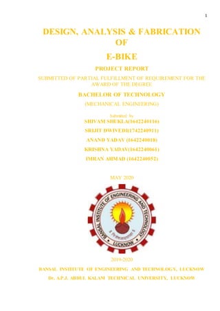
  • 1. 1 DESIGN, ANALYSIS & FABRICATION OF E-BIKE PROJECT REPORT SUBMITTED OF PARTIAL FULFILLMENT OF REQUIREMENT FOR THE AWARD OF THE DEGREE BACHELOR OF TECHNOLOGY (MECHANICAL ENGINEERING) Submitted by SHIVAM SHUKLA(1642240116) SRIJIT DWIVEDI(1742240911) ANAND YADAV (1642240018) KRISHNA YADAV(1642240061) IMRAN AHMAD (1642240052) MAY 2020 2019-2020 BANSAL INSTITUTE OF ENGINEERING AND TECHNOLOGY, LUCKNOW Dr. A.P.J. ABDUL KALAM TECHNICAL UNIVERSITY, LUCKNOW
  • 2. 1 DESIGN, ANALYSIS & FABRICATION OF E-BIKE PROJECT REPORT SUBMITTED OF PARTIAL FULFILLMENT OF REQUIREMENT FOR THE AWARD OF THE DEGREE BACHELOR OF TECHNOLOGY (MECHANICAL ENGINEERING) Submitted by SHIVAM SHUKLA(1642240116) SRIJIT DWIVEDI(1742242911) ANAND YADAV (1642240018) KRISHNA YADAV (1642240061) IMRAN AHMAD (1642240052) BANSAL INSTITUTE OF ENGINEERING AND TECHNOLOGY, LUCKNOW MAY 2020 2019-2020 BANSAL INSTITUTE OF ENGINEERING AND TECHNOLOGY, LUCKNOW Dr. A.P.J. ABDUL KALAM TECHNICAL UNIVERSITY, LUCKNOW BANSAL INSTITUTE OF ENGINEERING AND TECHNOLOGY, LUCKNOW
  • 3. 2 CANDIDATE'S DECLARATION I hereby certify that the work which is being presented in the project report entitled “E-BIKE ” by “SHIVAM SHUKLA” in partial fulfillment of requirements for the award of degree of B.tech (ME) submitted in the Department of ME at under “BANSAL INSTITUTE OF ENGINEERING AND TECHNOLOGY, LUCKNOW” AKTU, LUCKNOW, is an authentic record of my own work carried out during a period from JANUARY 2020 to MAY 2020 under the supervision of Mr. ADARSH PATEL. Signature of the Student This is to certify that the above statement made by the candidate is correct to the best of my/our knowledge. Signature of the SUPERVISOR (S) The B.tech Viva –Voice Examination of SHIVAM SHUKLA has been held on ____________ and accepted. Signature of Supervisor(s) Signature of External Examiner Signature of H.O.D. ABSTRACT
  • 4. 3 During the revolution for the eco-friendly technologies bicycles were the most depended modes of transportation, along with this the consideration of the increase in fuel price and the environmental factors we must admit that it is far more better to use a bicycle over a motor vehicle for short distance travelling. Imagine how useful would the bicycle be if even the small effort applied by man for climbing slopes and riding on rough terrain is reduced in it. We thought the same way to develop the basics of our project “The e-Bike”. The unit developed by us is a combination of the standard geared bicycle with an electric power motor cum alternator that would assist the rider throughout his journey. The system is modified in such a way that the rider can make choice of which mode he prefers i.e. he can either choose the bicycle to be driven completely with the electric motor or he can choose it to be driven manually by himself. The idea of mounting the motor cum alternator assembly onto a geared bicycle was to reduce the effort to-be applied for extra little weight that the rider will have to take along with the bicycle. Detailed study about the gross weight has been mentioned inside the report. The unit has been designed in such a way that people of any age group can depend on it. Our idea of implementation of the project was mainly biased towards providing inter college transportation system and to reduce the use of automobiles inside the as a tribute to the “GREEN ENERGY”. KEYWORDS:Hybrid bicycle; PMDC motor cum alternator; flywheel; multi-crank freewheel; sprockets; base plates.
  • 5. 4 LIST OF FIGURE FIGURE NO. FIGURE NAME PAGE.NO. 01. DC MOTOR 10 02. BATTERY 11 03. CHAIN DRIVE 12 04. BRAKING SYSTEM 12 05. VARIOUS TYPE OF SPROCKETS 13 06. E-BIKE FAST DIAGRAM 14 07. HOUSE OF QUALITY ANALYSIS 15 08. MOTOR DECISION MATRIX 16 09. E-BIKE PARTS & ACCESSORIES 18 10. (a) PMDC MOTOR (CROSS-SECTION) 21 (b) PMDC MOTOR (CROSS-SECTION) 11. FLY WHEEL CAD DRAWING 21 12. CAD DRAWING OF MULTI CRANCK 22 FREEWHEEL 13. (A) CAD DESIGN OF SPROCKETS 23-24 (B) CAD DRAWING OF SPROCKETS 14. CIRCUIT DIAGRAM & 25 ELECTRICAL CONNECTIONS 15. PROTOTYPE 26 16. EVOLUTION OF SCIENTIFIC PRODUCTION IN 28 RELATION TO THE ELECTRIC BICYCLE
  • 6. 5 17. TYPES OF SCIENTIFIC PRODUCTION 29 REFERRED TO THE ELECTRIC BICYCLE 18. DISTRIBUTION BY THEMATIC CATEGORY OF 29 SCIENTIFIC PRODUCTION IN RELATION TO ELECTRIC BICYCLE 19. GEOGRPHIC DISTRIBUTION BY COUNTRIES OF 30 SCIENTIFIC PRODUCTION IN RELATION TO ELECTRIC BICYCLES 20. CLOUD WORD OF THE WHOLE KEYWORDS 31 RELATED TO ELECTRIC BICYCLE 21. MAIN KEYWORDS USED BY THE COMMUNITIES 33 DETECTED IN THE TOPIC ELECTRIC BICYCLE 22. ELECTRIC BICYCLE KEYWORDS NETWORK & 33 THIER COMMUNITY DETECTION 23. AUTOMOTIVE ALTERNATOR 37 24. WYE CONNECTION STAR & DELTA 38 25. P-CHANNEL & N-CHANNEL MOSFETS 39 26. BATTERY CONNECTIONS 40 27. THOTTLE 41
  • 7. 6 ACKNOWLEDGEMENT I would like to place on record my deep sense of gratitude to Mr. ADARSH PATEL Dept. of Mechanical Engineering, B.I.E.T, Lucknow, India for his generous guidance help and useful suggestions. I express my sincere gratitude to Mr. ADARSH PATEL, HOD in Department of Mechanical Engineering B.I.E.T, Lucknow, for his stimulating guidance, continuous encouragement and supervision throughout the course of present work. I also wish to extend my thanks to Mr. VIMAL VISHWAKARMA for their insightful comments and constructive suggestions to improve the quality to the research work. I am extremely thankful to Prof. S.K AGRAWAL Group Director, B.I.E.T lucknow for providing me infrastructural facilities to work in without which this work would not have been possible. Name of Student- SHIVAM SHUKLA (1642240116) SRIJIT DWIVEDI (1742240911) KRISHNA YADAV (1642240061) ANAND YADAV (1642240018) IMRAN AHMAD (1642240052)
  • 8. 7 CONTENTS PAGE NO. Candidates declaration...............................................................................................................02. Abstract......................................................................................................................................03. List of figure..........................................................................................................................04-05. Acknowledgement.....................................................................................................................06. Chapter 1 : INTRODUCTION.....................................................................09-13. 1.1 Principle 1.2 Working medium 1.3 Operation 1.4 Components of E-bike 1.4.1 Dc motor 1.4.2 Platform 1.4.3 Battery 1.4.4 Chain drive 1.4.5 Braking system 1.4.6 Sprockets Chapter 2 : STRATEGIC GOALS AND DESIGN REQUIREMENTS..14-18. 2.1 Customer Requirements Analysis 2.2 Budget… 2.3 Initial Project Management Plan Chapter 3 : DESIGN AND IMPLEMENTATION OF E-BIKE..............19-27. 3.1 Hybrid systems 3.1.1 Basic components 3.2 Electrical system design 3.2.1 Electrical connections 3.3 Calculations 3.4 Working of prototype Chapter 4 : PRODUCTION.........................................................................28-33. 4.1 Evolution of Scientific Production 4.2 Types of Publications and Thematic Categories 4.3 Distribution of Publications by Countries and Institutions 4.4 Keyword Analysis 4.5 Analysis of the Interconnection between Keywords: Community Detection
  • 9. 8 Chapter 5 : DESIGN OF ELECTRIC BIKE.............................................34-37. 5.1 Design of shaft 5.2 Design of sprocket and chain for electric bike 5.3 Calculations of factor of safety 5.4 Advantages 5.5 Disadvantages Chapter 6 : TECHNICAL DISCRIPTION................................................37-42. 6.1 HARDWARE DESIGN 6.1.1 Automotive Alternator 6.1.2 MOSFETs Connections 6.1.3 Battery Connections 6.1.4 Throttle 6.2 CONTRIBUTION OF TEAM MEMBERS RESULT AND DISCUSSION..........................................................................43. CONCLUSION...................................................................................................44. Appendix 1-Technical Roles, Responsibilities, and Work Accomplished.........................45-46. Appendix 2- References..........................................................................................................47.
  • 10. 9 Chapter-1 Introduction and Background Energy crisis is one of the major concerns in today’s world due to fast depleting resources of petrol, diesel and natural gas. In combination with this, environmental decay is an additional factor which is contributing to the depletion of resources which is an alarming notification. Our paper proposes the solution for this above perilous problems. The system which we innovated is the Electric Bike. This project has various benefits both to the members of the team and also external benefits thereby making awareness of using alternative modes of transport. The Electric Bike which works on the battery that is powered by the motor is the general mode of transport for a local trip. The solar panels can be alternative source for this by adding it to the system. The Electric bike which will be running on battery, the power is supplied by the motor, thereby supplying this power to drive the other gear components. The main purpose of using this E-bike is that it is user friendly, economical and relatively cheap. The efficiency of this system undeniable compared to conventional modes of transport. The following table shows the specification of various electric bikes used in few countries: Table 1 Specifications of E-Bike in various countries Country Type of bike Speed limit in km/hr Watt Weight in kgs Age required in yrs Australia Pedal 25 250 None None Canada Hand 32 500 None Various China P/H 30 200 20 None Norway Pedal 25 250 None None Israel Pedal 25 250 30 14 UK Hand 27 250 40 14 Taiwan Hand 25 200 None None US Hand 25 750 None None China P/H 30 500 None None 1.1What is Electric Bike? The Electric bike is a bike which is driven with the help of battery which is coupled to electric motor. Main principle: It works on the principle that the electromotive force of an A.C. motor which receives electrical energy stored in D.C. battery is converted with the help of D.C. to A.C. converter. Working medium: Here for the motivation of prime mover the chemical reaction takes place from which an energizing current is evolved which is responsible for the working. 1.2 The working medium is sulphuric acid which is separated into columns of H ions and negative SO4 ions. When mixed with water. If the poles of the cell are connected by a load, the flow of the electrons is from negative to positive. A bivalent positive lead is produced from neutral lead when combined with bivalent negative of SO4 group to form lead sulphate. This results due to scarcity of electrons at negative pole. Through the electron supply a bivalent
  • 11. 10 positive lead is produced at positive pole from quadric valent positive lead. A combination of SO4 comes into existence thereby ruling the combination of O2 which leads to formation of PbSO4. The atoms of oxygen and hydrogen from electrolyte are released together to form water thereby decreasing the density of battery acid. 1.3-Operation:In this a DC waveform which is obtained id made sinusoidal due to operational transistorized D.C. to A.C. amplifying circuit by switching the electric energy in the form of electric current which flows from battery to D.C. to A.C. converter circuit. By using amplifier circuit the small A.C. current is amplified again. In order to drive the circuit through the condenser, this amplified current is fed to the stator winding of the A.C. motor. The condenser which is used acts as a storage of electric energy and delivers at the time of requirement. The sprocket wheel installed on motor shaft is driven by the motive power of the electric energy. The rear sprocket wheel is being rotated by the chain drive mechanism on which the other two remaining sprocket wheels are installed. The wheel is driven by the rear wheel installed on the rear sprocket. Thus the electric bike is mobilized by using electric power.  COMPONENTS OF E – BIKE The Electric bike consists of following components which are DC motor, Frame, Platform, Battery, Drive etc. (Barve, Design and Development of Solar Hybrid Bicycle, 2016) 1. Dc motor: The motor is having 250 watt. Capacity with maximum 2100 rpm. Its specifications are as follows: Current Rating: 7.5amp Voltage Rating: 48 Volts Cooling: Air – cooled Bearing: Single row ball
  • 12. 11 FIGURE-1 : DC MOTOR 2. Frame: The Frame is made up of M.S. along with some additional light weight components. The frame is designed to sustain the weight of the person driving the unit, the weight of load to be conveyed and also to hold the accessories like motor. Also it should be design to bear and overcome the stresses which may arise able to due to different driving and braking torques and impact loading across the obstacles. It is drilled and tapped enough to hold the support plates. 3. Platform: The Platform is designed with robust base so that it can hold the load along with the weight of the driving person uniformly. It is fabricated from Mild Steel at a specific angle in cross section and welded with a sheet of metal of specific thickness. The platform’s alignment is kept horizontal irrespective whether it is loaded or unloaded and this is directly bolted and welded to the frame. 4. Battery: The battery also acts as a condenser in a way that it stores the electrical energy produced by the generator due to electrochemical transformation and supply it on demand. Battery is also known as an accumulator of electric charge. This happens usually while starting the system.
  • 13. 12 FIGURE-2 : BATTERY 5. Chain Drive: A Chain is an array of links held together with each other with the help of steel pins. This type of arrangement makes a chain more enduring, long lasting and better way of transmitting rotary motion from one gear to another. FIGURE-3 : CHAIN DRIVE The major advantage of chain drive over traditional gear is that, the chain drive can transmit rotary motion with the help of two gears and a chain over a distance whereas in traditional many gears must be arranged in a mesh in order to transmit motion. 6. Braking System: For the braking system it is convenient to use braking system used in band brake system which consist of spring loaded friction- shoe mechanism, which driven with the help of hand leaver FIGURE-4 : BRAKING SYSTEM
  • 14. 13 7. Sprockets: The chain with engaging with the sprocket converts rotational power in to rotary power and vice versa. The sprocket which looks like a gear may differ in three aspects:  Sprockets have many engaging teeth but gears have only one or two.  The teeth of a gear touch and slip against each other but there is basically no slip page in case of sprocket.  The shape of the teeth are different in gears and sprockets. (Barve, Design and Development of Solar Hybrid Bicycle, March 2016) FIGURE-5 : VARIOUS TYPES OF SPROCKETS
  • 15. 14 Chapter-2 Strategic Goals and Design Requirement 2.1 Customer Requirements Analysis The first step taken during the product planning phase was the analysis and evaluation of the project requirements given by the customer or sponsor. To effectively plan goals and an efficient critical path, a design proposal needed to be identified quickly. The first step in understanding the sponsor’s requirements was to set up an interview to discuss how the design has the potential to positively impact society and to discuss design goals. My Team learned that the most important goal was the ability to make the design as inexpensive as possible. Other important goals were to maximize efficiency and power consumption by pulsing the rotor and stator coils, achieve a wide range of speeds, increase the torque at low speeds, and implement regenerative braking. In order to understand and implement a design that met all of the requirements, multiple analysis techniques were performed. One technique was the development of a FAST diagram in order to understand and define the product functionality and the scope of the project. Figure 6 below is the our team FAST diagram. FIGURE-6 : E-BIKE FAST DIAGRAM
  • 16. 15 The basic function of the design is to use the alternator to control the electric vehicle’s speed. This is done by either speeding up or slowing down the alternator. In order to speed up the alternator, the throttle needs to be applied. In order to speed up the alternator shaft, current needs to be applied to the stator and rotor at the quadrature angles. This is done using the microcontroller and the software logic to switch the MOSFETs that are connected to the stator and the rotor. In order to slow down the electric vehicle, the brake lever needs to be applied. Slowing down the alternator is achieved by slowing down the alternator shaft. This is done using regenerative braking. Regenerative braking is executed by drawing current from the alternator to charge the battery that is supplying the circuit and the alternator. This can be done by controlling the field using the microcontroller and the software. Another technique that was utilized was the House of Quality analysis technique. This analysis method proved to be quite useful because it helped our Team understand the Critical Customer Requirements for the design. This helped prioritize the project needs and gave direction for which specifications to look for when selecting components. The House of Quality Matrix is shown in Fig.7 FIGURE-7 : HOUSE OF QUALITY ANALYSIS
  • 17. 16 This type of analysis was very helpful because it was a tool used to assist in data based decision making. It also helped to reduce design uncertainty because by understanding the customer requirements and how the quality characteristics or measures affect them. It was easy to clarify how the data collected would help determine a best approach. It was also a good tool to determine which measurements would prove to be of higher importance for selecting a design that best matches all of the specifications. From the House of Quality, it was determined that efficiency and speed were the easiest customer requirements to analyze using the quality characteristics. One of the harder requirements to measure was the reliability. It was also noticeable that high output power and power dissipation had a strong inverse relationship because the more output power of the alternator that is measured, the lower the power loss or dissipation. Some of the other strong positive relationships as seen in the house of quality were high rpm and current draw, high current draw and output power, and high output power and high torque. Another useful piece of this type of analysis was being able to prioritize customer requirements. The most important customer requirements for this design were cost, efficiency, speed, and reliability. Once the main project goals were prioritized, project design functionality planning could begin. To make critical design component selections, decision matrices were developed which allowed for the comparison of different options in relation to the established design goals and sponsor requirements. The first major decision encountered was the type of motor to be used with the prototype. From the motor decision matrix in Figure 8, an automotive alternator clearly met the goals for the project over other available options, an AC motor or a brushless DC motor. As can be seen from the decision matrix below, the alternator is significantly better than its counterparts with regards to cost and speed. FIGURE-8 : MOTOR DECISION MATRIX
  • 18. 17 2.2 Budget One of the key constraints of this project was developing a design that is both cost effective and efficient. The most expensive portion of the project are the automotive alternators, which cost around 1400 to 2100rs. The use of these alternators instead of brushless DC motors will save at least 4200rs per motor. Like most of the parts that are required for this project, the automotive alternators were already provided to the team; therefore the cost is not tracked in the 35000rs budget, but will be included in the cost per unit budget. Additional parts that were needed include the diametrically magnetized magnet, the AMS AS5132 rotary sensor, the P -channel and N-channel power MOSFETs, terminal blocks, power recovery diodes, and an external throttle. Other hardware circuit components such as colour coded resistors, NPN and PNP transistors, Zener diodes, capacitors, heat sinks, and header pin connectors that were required for the MOSFET switching PCB were not included in the budget since they were obtained from the ECE shop at no cost. These circuit items were included in the cost per unit budget. In order to have the opportunity to implement design changes throughout the design process, extra components were ordered just in case components were damaged during testing. The table below shows the cost of all of the components ordered by my team throughout the design process. The total prototype design cost was 23277.8, which is within the 35000 budget for the semester. The cost of the PCB fabrication, 10 AWG wiring used for the stator coils and battery connections, two 12V batteries, and all other hardware components mentioned above. This is because these components were obtained from the sponsor or from the ECE shop. A majority of the prototype design costs were shipping costs. For example, the shipping cost for 26.6rs magnets was greater than the product cost. For the per unit production cost, the cost was calculated without the shipping costs of the parts. A per unit production cost was also calculated below to show the cost to make one prototype E-bike motor and controller. It is easy to see that the cost of one production unit is significantly lower than the cost to make the prototype design. This is due to the fact that additional components were ordered even though not all of them were necessary. For future production, terminal blocks like those used in the prototype design will not be necessary for attachment to the PCB from the stator coils. Prices for components such as the AMS sensor, recovery power rectifier, P-channel and N-channel MOSFETs, 10 AWG wire are much cheaper if bought in bulk quantity. For a production setting, all of these components will be purchased in bulk.
  • 19. 18 2.3 Initial Project Management Plan The initial project timeline consisted of seven main phases. These phases include project definition, research of new designs, development of conceptual designs, initial prototype preparation, initial testing, initial prototype construction, and final design construction. The project schedule and project timing was organized the seven main phases, which were further broken down into tasks. These tasks consisted of a start date and an end date. The project schedule consisted of a critical path. Tasks on the critical path could not be started unless the task before was completed. These tasks were the most critical to the project because any delay caused a delay to the whole project. It was important to try to shift the critical path. For the most part, The only modification came near the end of the design process in the “Construct Final Design” phase. Since the team decided to go with one PCB design, the “design PCB layout” and “PCB fabrication/soldering” tasks were moved to the “Construct Initial Prototype” phase. The project prototype and final design were very similar, and the PCB was fabricated before testing efficiency. This was because in order to run and test the high current portion of the circuit, a PCB needed to be fabricated. A breadboard could not be used for these tests. FIGURE-9 : E-BIKE PARTS AND ACCESSORIES
  • 20. 19 Chapter-3 Design and Implementation of E-Bike Global warming and scarcity of traditional resources are becoming major problems in the current scenario. Due to the economic challenges India is facing in automotive sector the hybrid bicycle market has a huge growth potential. People try to move towards "clean" energies. These facts among others will leverage the electric bicycle industry on the top of the agendas not only in India. Moreover the vision of an electric engine, which supports the muscular strength, became reality. Bicycles with such a supporting electric engine belong to the innovative vehicles, which are wholeheartedly suitable for everyday life. In face of continuous climate discussions and permanent traffic jams, electric bikes have the potential of solving such issues and making a more energy efficient and environment friendly mobility possible. Accordingly a continuous trend towards electric bicycles can be expected simultaneously in whole of India. So it becomes very necessary to manufacture the electric cycles so cheaply that the common people in our country can afford to buy it. The currently existing electric scooters are far more costly and due to budgetary constraints a middle class person cannot afford such a locomotive at his place. Along with the development of technologies the theory must be also implemented to design and manufacture a product that can be sold off at a greater frequency, which has a very low production cost and one that is of good quality. In order to implement all the above ideas, we planned to make the design and product in such a manner that it can be completed with the existing “E-Bikes” in the market. A. Background The basic idea is to attach a motor to the cycle for its motion. A motor that is powered by a battery and that can be switched on during difficult terrains and switched off and pedal to get the battery re-charged during motion in a flat terrain. The idea came into our mind as different stages of project planning, firstly we wanted to implement a simple moving system so the projection of cycle as a system came into our mind, and second stage was adding a necessarily useful component into it that can be beneficial in the future and for common people, falling into the current trend was that of hybrid system so we ended up planning to assemble a motor unit into the cycle drive. There were many issues that came up while making such a system major one of them being the power of the motor to be used, since no such previous systems were made we could not predict the type of motor which we should go for. Second thing being the weight factor, the addition of extra weight on to the system, which can cause discomfort to the rider while normal pedalling. Third was the type of battery to be used, we should go for a battery that has longer life, economically viable, and also has less maintenance issues. Fourth issue was that self-recharging a battery with a motor alternator unit that too with the simple cranking motion of the cycle was not viable, we had to utilize a mechanism that can come in handy here and that was by using the flywheel rotation technique.
  • 21. 20 B. MechanicalDesignandSystem Integration The main aim was to fabricate a prototype that would be very light and comfortable for the rider to handle . As the motor and other drive components would take in most of the free space in the system our design challenge was to make the motor-alternator unit as a single system. This was our major challenge, for this purpose we developed the motor cum alternator at its minimum possible size and also at the lowest possible cost. Mounting the battery was another challenge, the location of the mounting could have been anywhere in the rest of the space available near the motor or we could have used up the empty space near the carrier. Keeping in mind the comfort of the rider the battery casing was mounted behind the rider, near the carrier location. Looking at the complicated arrangement of the system one may easily think that the drive arrangement could have been completed in a single step i.e. the direct link from the motor to the drive. But the real fact is that this would make the cranking for self- recharging mechanism difficult, since the speed for alternator recharging cannot be achieved by simple cranking a flywheel has to be used to store the cranking energy and thus the rotation and cranking at normal cycling becomes easier. 3.1 HYBRID SYSTEMS A. Overview This section of the paper deals with the mechanical design of the system and the various parts used in the system integration. The power transmission system consists of the motor , the chain sprockets, flywheel, housing and the rear wheel. However, before we could select these components, we performed some basic calculations relating energy transfer through the system. Primarily we focused on the current requirements of the system, and a number of torque-speed relationships. Both the acceleration on flat ground and hill climbing ability of the system depend on how much torque can be delivered by the various system components. Before we could size the batteries, we needed to estimate when the motor would demand the most current and the duration that it would draw its peak current. These situations would be at start up (acceleration) and when climbing a gradient. The main components affected by the following calculations are the motor and the battery. B. Components of Hybrid System 1. PMDC MOTOR (Permanent magnet DC motor): Permanent magnet DC brushed motors (PMDC motors) consist of permanent magnets, located in the stator, and windings, located in the rotor The ends of the winding coils are connected to commutator segments that make slipping contact with the stationary brushes. Brushes are connected to DC-voltage supply across motor terminals. Change of direction of rotation can be achieved by reversal of voltage polarity. The current flow through the coils creates magnetic poles in the rotor that interact with permanent
  • 22. 21 magnet poles. In order to keep the torque generation in same direction, the current flow must be reversed when the rotor north pole passes the stator south pole. For this the slipping contacts are segmented. This segmented slip ring is called commutator. Figure 3(a) shows angular position just before commutation of rotor winding current and Figure 3(b) after it. FIGURE-10 (a): PMDC Motor (Cross-Section) FIGURE-10 (b): PMDC Motor (Cross-Section) 2. Flywheel: A flywheel is a rotating mechanical device that is used to store rotational energy. Flywheels have a significant moment of inertia and thus resist changes in rotational speed. The amount of energy stored in a flywheel is proportional to the square of its rotational speed. Energy is transferred to a flywheel by applying torque to it, thereby increasing its rotational speed, and hence its stored energy . Conversely, a flywheel releases stored energy by applying torque to a mechanical load, thereby decreasing its rotational speed. Flywheels are typically made of steel and rotate on conventional bearings; these are generally limited to a revolution rate of a few thousand RPM. Some modern flywheels are made of carbon fiber materials and employ magnetic bearings, enabling them to revolve at speeds up to 60,000 RPM. Our design, due to the simplicity of its application, uses a flywheel which is made up of cast iron having a diameter of 17cm.Carbon-composite flywheel batteries have recently been manufactured and are proving to be viable in real-world tests on main stream cars. Shows the CAD drawing of the flywheel. FIGURE-11 : FLY WHEEL CAD DRAWING
  • 23. 22 3. Housing: Housing is used for making an interconnection between the rotating flywheel and the sprocket at the other end. It is this sprocket from the rotating flywheel connected to a shaft that drives the multi crank free wheel. The housing is attached with a rubber bush to avoid the shocks. They are normally used in door hinges for making perpendicular movable connections. The ball bearing inside the housing chamber allows the free rotation of the connecting shaft inside the housing. DesignSpecifications:- Length: 1m; External Diameter: 0.7m; Internal Diameter: 0.5m; Thread Pitch:0.024m. 4. Multi-crank Freewheel: Multi crank freewheel is developed as alternate mechanism to drive the rear wheel from the motor power the crank is developed in such a way that the ball bearing has a special effect when rotation on one direction through motor happens the ball bearing external lock holds the moving pedal thus restricting its motion, on the other hand when the rotation with pedal happens the bearing engages with the pedal and thus the drive through cranking happens. For developing, the crank was attached with another crank of the same diameter so that there will not be any difference in the pedaling effect to the rider. DesignSpecifications:- Crank Diameter: 0.18m; Number of Teeth: 52 the CAD drawing of multi-crank freewheel. FIGURE-12 : CAD DRAWING OF MULTI CRANCK FREEWHEEL
  • 24. 23 5. Sprockets: A sprocket or sprocket-wheel is a profile wheel with teeth, cogs, or even sprockets that mesh with a chain, track or other perforated or indented material. The name 'sprocket' applies generally to any wheel upon which are radial projections that engage a chain passing over it. It is distinguished from a gear in that sprockets are never meshed together directly, and differs from a pulley in that sprockets have teeth and pulleys are smooth. Sprockets are used in bicycles, motorcycles, cars, tracked vehicles, and other machinery to transmit rotary motion between two shafts where gears are unsuitable or to impart linear motion to a track, tape etc. Perhaps the most common form of sprocket may be found in the bicycle, in which the pedal shaft carries a large sprocket-wheel, which drives a chain, which, in turn, drives a small sprocket on the axle of the rear wheel. Early automobiles were also largely driven by sprocket and chain mechanism, a practice largely copied from bicycles. Sprockets are of various designs, a maximum of efficiency being claimed for each by its originator. Sprockets typically do not have a flange. Some sprockets used with timing belts have flanges to keep the timing belt centered. Sprockets and chains are also used for power transmission from one shaft to another where slippage is not admissible, sprocket chains being used instead of belts or ropes and sprocket-wheels instead of pulleys. They can be run at high speed and some forms of chain are so constructed as to be noiseless even at high speed. FIGURE-13 (A): CAD DESIGN OF SPROCKETS
  • 25. 24 Sprockets (Front and Side Views) DesignSpecifications:- Sprocket 1 (connected with the motor) Number of Teeth: 16; Diameter: 70mm. Sprocket 2 (connected with housing) Number of Teeth: 16; Diameter: 70mm the CAD drawing of multi-crank freewheel. FIGURE-13 (B): CADDRAWING OF SPROCKETS 3.2 ELECTRICAL SYSTEM DESIGN A. Overview The PMDC motor had to be regulated by a mechanism which involved a DC motor driver .This driver had specifications able to withstand up to 20A which was key to this project as varying loads would undoubtedly draw more current. So the rated current rating had to be high enough to withstand this. The driver is controlled by an Arduino Board which receives input signals via. a potentiometer (variable resistance). The Arduino board was programmed in such a way that varying the resistance in the potentiometer would result in an equivalent value of bytes which the program could comprehend and translate to proportional DC motor speeds.
  • 26. 25 B. Programming The programming was done on the software accompanied with the Arduino Board. When the “initialise motor” command is used charge starts flowing to the motor through the driver. When the program enters the loop, the potentiometer values (read as resistance pulse values) gets translated to equivalent bytes that lets the Board allow charge to pass through the motor thus increasing/decreasing the speed. Once the loop is exited, the program goes back to initial value. C .ElectricalConnections There are different approaches to driving a motor when it comes to driving a motor with Arduino. If a simple relay is used to drive a motor it can only turn the motor on and off. In case a single transistor like TIP120 (BJT) or IRF510 (MOSFET) is used, it is possible to control the speed of the rotation. There exist smarter DC motor drivers (so called H-bridge) that can control the direction of rotation and even brake. An example of such a driver is MC33887 Motor Driver which is affordable and versatile. This driver can control a single DC motor with maximum consumption of 2.5A and peaks of 5A. Motor voltage can range from 5-28V which makes it an excellent general purpose motor driver shows the circuit diagram and shows the electrical connection. Electrical Connections Circuit Diagram FIGURE-14 : CIRCUIT DIAGRAM & ELECTRICAL CONNECTIONS
  • 27. 26 3.3. CALCULATIONS A. Maximum currentdrawn from the cycles at twostages:- 1. During Acceleration; 2. During Hill Climbing 1. During Acceleration the forces acting on the system are: Drag force; Friction from tires; Force due to gravity. There is a major change of energy from electrical to K.E+P.E K.E = ½.m.v2 Where the value of ‘v’ keeps varying. Electrical energy = V.I.T Final K.E = voltage rating x current required x time to accelerate Voltage provided=36v Maximum mass = 120Kg(value taken is considering mass of man 100 kg+unit wt. 20kg) K.E = ½ x 120 x (25)2 = 375500 W. (POWER CONSUMED) 375=36 x I x20(s), I=0.52A; 375=36 x Ix 40(s), I=0.26A; 375=36 x Ix 60(s), I=0.17A [These values shows the current drawn when unit reaches 25Km/hr. at various intervals] Current drawn from the unit is more when time taken is less and vice versa. Considering that the cyclist can achieve the25km/hr. mark in 60(s), the current drawn will be 0.17A. But practically the values varies from person to person hence an average value is calculated to be about = 0.3166 ≈ 0.32 A. 2. Gradient ascent requirements (During hill climbing) Gradient is given by, SinѲ=ΔH/Δx Maximum power drawn during hill climbing based on the calculation is 600W; hence the motor of that rating or more than that rating must be used. B. Selection of Speed and Gear Reduction For a desired top speed of 25Km/hr. Gear Ratio = 1:9 (drive: driven) Speed (motor) = 3100 rev/min x 27p/rev x 60 minutes/hr. x 1ft/12 inches x 1 mi/5280ft = 24.9 KM/Hr. Desired speed = 25km/hr. Therefore speed of motor/ desired wheel speed = 24.9/25 = 0.996̴0.9 (taking the lower limit). C. Motor Starting Current Motor starting current (from dead start) =3.44A. Motor starting current (cont. motion) =1.05A.
  • 28. 27 3.4 WORKING OF THE PROTOTYPE The 150 watt PMDC motor which gives a 1000 RPM at 12V and 15A rating was linked with a flywheel using the sprocket ratio at 16:40 (motor : flywheel) teeth ratio, the shaft from the flywheel was then linked to the sprocket on the other side with a housing. The drive from this sprocket to the multi crank freewheel is attached again at 16:52(sprocket: crank freewheel) teeth ratio. These ratios were selected for maximum efficient power transmission with minimal loss. The drive from this crank is directly linked with rear wheel sprocket that facilitates its motion. When the motor is switched ON, the motor draws current from the two dry cell batteries connected in parallel that would give an effective discharge of 12V and 14A. Since the motor uses maximum current (11 amp) during starting a battery of that specification was used. Later on as the effective speed increases the current drawn reduces to 1.77A. Figure shows the final assembled prototype of the hybrid bicycle. FIGURE-15 : PROTOTYPE Final Assembled Prototype The motion of the motor actuates the flywheel whose rotation in turn drives the shaft through the housing and make the sprockets at the other end move which would drive the multi crank and thus the rear wheel. It should be noted that while the motor is in working mode the pedals won’t rotate which would otherwise cause discomfort to the rider. For this to work we have added a ball bearing at the crank spot that would disengage the inner ring while motor is in rotation and engage them when the motor is switched off.
  • 29. 28 Chapter 4 PRODUCTION 4.1. Evolution of Scientific Production From 1973 to 2017, the search yielded 896 document results, whose temporal distribution is show in Figure. It must be noted that the search has no data prior to this date, for this reason 1973 is considered the first year of this search. It is observed that the increase begins in 2003, and 2008 is the year when scientific production increases significantly. These publications are written mostly in English in more than 90% of cases, although the Chinese language also appears strongly since 2001,with 7.5%, other languages are already anecdotal with less than 1% and included Japanese, Dutch, German, Polish, Russian, Spanish, and French. FIGURE-16 : Evolution of the scientific production in relation to the electric bicycle (1973-2017) 4.2. Types of Publications and Thematic Categories In the analysis of the means of scientific diffusion, generally, the most used means are journal, except in areas of novel research, where the search terms appear mostly in specialized scientific conferences. This is what occurs in our case, where conference papers account for the most part, 54% of the total, while articles in journals account for
  • 30. 29 43%. Figure shows the percentage of the types of scientific production distributed on the theme of electric bicycle. FIGURE-17 : Types of scientific production referred to the electric bicycle (1973–2017). The thematic categories in which the scientific work is classified show the approaches from which the problem under study is approached. In our case, it is observed that the principal categories are: Engineering (42%), Computer Science (12%), Energy (10%), Social Sciences (10%), and Medicine (4%). FIGURE-18 : Distribution by thematic category of scientific production in relation to electric bicycles
  • 31. 30 4.3. Distribution of Publications by Countries and Institutions Figure shows the geographical distribution of the countries with publications in this field. The top ten countries concerned about this issue, as reflected in their scientific production, are, by order China, United States, Taiwan, Italy, Germany, Japan, South Korea, Australia, Malaysia, and Canada. FIGURE-19 : Geographic distribution by countries ofscientific production in relation to electric bicycles Table 1 shows that the institutions with more than 8 publications, of the 16 represented, 10 are from China: Southeast University, Tongji University, Tsinghua University, Zhejiang University, Southwest Jiaotong University, Beijing JiaotongDaxue, Chang’an University, Jilin University, Chinese Academy of Sciences, and Nanjing University of Aeronautics and Astronautics. 2 are from the USA: University of Tennessee, Knoxville and UC Berkeley, while a number of countries produceone publication and include Italy (Politecnico di Milano), Australia (Monash University), Taiwan include Italy (Politecnico di Milano), Australia (Monash University), Taiwan (Kao Yuan University Taiwan), and Portugal (Universidade de Lisboa). If the total citations (TC) in these publications are observed, the Tsinghua University leads, followed by the University of Tennessee.
  • 32. 31 4.4. Keyword Analysis The analysis of the keywords identifies or summarizes the work of the researchers . This section analyses the keywords obtained from the main query described in the methodology section. In the overall articles obtained from the query, the frequency of appearance of each keyword has been obtained. In Figure , a word cloud has been represented where size and centrality show the importance of that keyword within the total publications, defined by the highest frequency of occurrence or the number of times it is repeated. If the main query is filtered by each of the major countries by number of publications, the main keywords of these countries are obtained. Therefore, the three main keywords of the top ten countries. The keywords of the countries that least resemble the rest are those of Japan and Australia, and both have a gender component that is very much present in their studies. On the other hand, if the main search is limited to a particular keyword, the frequency of occurrence of this keyword for each year can be obtained. Figure shows the evolution over time of the top three keywords. Note that the search is limited to the last ten years, from 2007 to 2017. This is due to the small difference existing in earlier years (note that in 2007 two of these keywords had no values). The keywords “Electric Vehicle” were almost always above the others but they have emerged mainly since 2015. The other two keywords, “Sporting Goods” and “Transportation”, were in the same rank until 2012. Since then, sporting goods began to distance itself upwards. In this part of the analysis, it is worth noting that the electric bicycle is no longer just an alternative for transportation, but a means of daily sports practice to improve health. Indeed, the electric bicycle is considered a vehicle. It is important to highlight this fact, because for many countries it is proposed as a solution to the problem of personal transport. On the other hand, in the US, “sporting goods” refers to items that are purchased for recreational purposes. FIGURE-20 : Cloud word of the whole keywords related to electric bicycle
  • 33. 32 4.5. Analysis of the Interconnection Between Keywords: Community Detection Considering a community as a system composed by multiple interdependent elements, with a very wide range of relationships that are variable and dependent, we could accept, conceptually, that communities are made up of a highly cohesive central core and peripheral spheres with unions increasingly weaker compared to the center. The central core would be structured by the most significant elements of the community, in terms of granting a definable individuality, evinced by the links between its constituents who share the strongest and most significant connections within the entire community complex. Communities or clusters are usually groups that are more likely to relate to each other than with members of other groups. Identifying communities is an interesting problem in our case because it will guide us around which way the main topics of the publications are grouped. For this specific analysis, we downloaded the keywords of each publication separately, generating a file line with up to six keywords used in each publication; this file was entered into a network analysis software that detected the main communities. Clusters with different colours have been shown and they are represented in the form of neural network. Each node is a keyword, and the thickness of the link between nodes is the frequency of that relationship. In the analysis of the publication of the electric bicycle, six communities have been detected using a community detection algorithm, and Table 3 shows their main keywords. To identify each cluster a proposed name is offered in the last column of the table. By order of importance they are: Transportation–Environment, Electrical engineering, Safety, Batteries, Sporting goods–Urban planning, and Mechanical engineering. Transport and environment is the first in order of importance, highlighting this cluster within world research, and above all the concern for air pollution in cities. As was expected, electrical engineering supports this technology, and it is quite logical that it ranks second. The risk factors for accidents have increased greatly with the increase in the number of electric bicycles, so the issue of safety appears as the third most important issue. Batteries rank fourth among the clusters, highlighting the improvement of batteries, especially
  • 34. 33 in charging systems and the increase in their autonomy. As mentioned above, it is surprising that the electric bicycle is part of the concept of sport, but its daily use undoubtedly promotes individual sport, and this can be a health enhancing sports routine. The mechanical approach is therefore the last of the categories. FIGURE-21 : Main keywords used by the communities detected in the topic electric bicycle FIGURE-22 : Electric bicycle Keywords network and their community detection
  • 35. 34 Chapter 5 DESIGN OF ELECTRIC BIKE 5.1 DESIGNING OF SHAFT BENDING: The force which develops across a specific cross section of the shaft, it generates stress at that point of cross section that are subjected to maximum loading. This internal or resisting moment gives rise to the stress called as bending stresses. Torsion: When the shaft which is twisted by the couple such that the axis of that shaft and the axis of the couple harmonize, that shaft is subjected to pure torsion and the stresses generated at the point of cross section is torsion or shear stresses. Combined Bending and Torsion: In actual practice the shaft is subjected to combination of the above two types of stresses i.e. bending and torsion. The bending stresses may occur due any one of the following reasons: 1. Weight of belt 2. Pull of belts 3. Eccentric Mounting of shafts/gears 4. Misalignment of shafts/gears On contrary, the torsional movement occurs due to direct or indirect twisting of the shaft. Hence at any given point on cross-section of the shaft, the shaft is subjected to both bending and torsional stresses simultaneously. Following stresses are taken in consideration while designing the shaft: Shaft design T = 36000 N mm T = 3.14 / 16 x σsx d3 Fs allowable = 80 N/mm2 6820 =3.14 x σsx d3/16 σs= 34.73 N/mm2 Material = C 45 (mild steel) σ ut= 320 N/mm2 ------------ PSG design data book. factor of safety = 2 σt= σb= σ ut/ fos = 320/2 = 160 N/mm2 σs= 0.5 σt = 0.5 x 160 = 80 N/mm2 σsis less then allowable so our shaft design is safe
  • 36. 35 5.2 Designof Sprocket and Chain for Electric Bike We know, TRANSMISSION RATIO = Z2 / Z1 = 66/11 = 6 For the above transmission ratio number of teeth on pinion and the number of teeth sprocket is in the range of 21 to 10, so we have to select number of teeth on pinion sprocket as 11 teeth. So, Z1 = 11 teeth SELECTION OF PITCH OF SPROCKET The pitch is decided on the basis of RPM of sprocket. RPM of pinion sprocket is variable in normal condition it is = 2100 rpm For this rpm value we select pitch of sprocket as 6.35mm from table. P = 6.35mm CALCULATION OF MINIMUM CENTER DISTANCE BETWEEN SPROCKETS THE TRANSMISSION RATIO = Z2 / Z1 = 66/11 = 6 which is less than 7 Dia. of small sprocket, Periphery = π × dia. Of sprocket 11 × 6.25 = π × D D = 11 × 6.25 / π D = 21.8 mm Dia. of sprocket, Periphery = π × dia. Of sprocket 66 × 6.25 = π × D D = 66 × 6.25/ π D = 131.3 mm So from table, referred from PSG Design Data book The minimum centre distance between the two sprocket = C’ + (80 to 150 mm) Where C’ = Dc1 + Dc2 2C’= 131.3 + 21.8 2C’ = 76.5 mm MINIMUM CENTER DISTANCE = 76.5 + (30 to 150 mm) MINIMUM CENTER DISTANCE = 170 mm CALCULATION OF VALUES OF CONSTANTS K1 K2 K3 K4 K5 K6 – (with help of PSG DesignData) Load factor K1 = 1.25 (Load with mild shock) Distance regulation factor K2 =1.25(Fixed center distance) Center distance of sprocket factor K3 =0.8
  • 37. 36 Factor for position of sprocket K4 = 1 Lubrication factor K5 = 1.5 (periodic) Rating factor K6 = 1.0 (single shift) 5.3 CALCULATION OF VALUE OF FACTOR OF SAFETY For pitch = 6.35 & speed of rotation of small sprocket = 2100 rpm Factor of Safety for this drive = 8.55 Calculation of Allowable Bearing Stress: For pitch = 6.35 & speed of rotation of small sprocket = 2100 rpm Allowable Bearing stress in the system = 2.87kg / cm2 =2.87 * 981/100 =28 N /mm2 Calculating Maximum Tension on Chain Maximum torque on shaft = Tmax= T2 = 6820 N-mm Where, T1 = Tension in tight side T2 = Tension in slack side O1, O2 = center distance between two shaft Sin ∝= R1 - R2 /O1O2 Sin ∝= 65.65 - 10.9 170Sin ∝= 0.33 ∝= 18.78 TO FIND  = (180 –2∝) X 3.14/180 = (180 –2*18.78) X 3.14/180 = 2.48 rad According to this relation, T1/T2 = e T1/T2 = e0.35 x 2.48 T1 = 2.38T2 We have, T = (T1 – T2) X R 6820 = (2.38 T2 – T2) X 65.65 T2 = 75.27 N T1 = 2.38 X 75.27 T1 = 179.16 N So tension in tight side = 179.16 N We know, Stress = force / area x 2 Stress induced = 179.16/ (3.14 * 32 / 4) x 2 Stress induced = 12.67 N /mm2 As induced stress is less than allowable stress =28N /mm2design of sprocket is safe
  • 38. 37 5.4 ADVANTAGES Less maintenance cost. Normal Drag/Pedal is possible when power is not in use. Deployable batteries – can be taken inside house. Cost of the unit is very low. Easy to carry since it is portable. Less energy consumed. High efficiency can be obtained if inverter is used. If using solar panel, free utilization of energy can be done.  5.5 DISADVANTAGES High intensity of wind load. High centre of gravity. Cannot tolerate drastic changes in environment. Needs Periodic Monitoring CHAPTER-6 TECHNICAL DISCRIPTION 6.1 Hardware Design 6.1.1 Automotive Alternator The automotive alternator is perhaps the most important component or piece of the design. Without the alternator, there would be no source of mechanical power to run the electric tricycle. After selecting an automotive alternator to be the motor for the design, it was important to select the correct stator coil orientation that best fit the design. The figure below shows a common automotive alternator and its main components.
  • 39. 38 FIGURE-23 : AUTOMOTIVE ALTERNATOR The main hardware components that utilized within the automotive alternator are the rotor and the stator. The rotor of the alternator consists of a coil of wire wrapped around an iron core. DC field current produces a magnetic field around the core. The stator is a set of coils fixed to the shell of the alternator. Magnetic field from the rotor couples to the stator coils producing current in the stator windings. These stator coils are placed 120 degrees apart, producing 3 separate phases. The automotive alternators used in this design are of the hybrid brushless variety, having no expensive, internal rare earth permanent magnets. Instead, the motors require that a small amount of current be passed through brushes to a coil in the rotor in order to magnetize it. Current is then applied to the outer stator coils in order to induce an electromagnetic force to turn the rotor. The stator has 36 coils around its perimeter. The test alternators have 36 coils that are wired into 3 phases connected in a “delta” pattern such that each phase has 12 coils and each coil is separated by 10 degrees around the stator. The first step in the hardware design process was to determine the most effective way to orient the stator coils in the alternator. As mentioned above, the alternator was originally connected in a delta configuration. Delta configuration allows for lower voltage but higher current. The figure below shows a delta connection and a Wye connection with a common. FIGURE-24 : WYE CONNECTIONS STAR & DELTA In order to precisely pulse only one stator coil at a time, the alternator was reoriented To a Wye connection with a common wire. This was less resistive than the delta connection and allowed for more current to pass through the stator windings providing higher RPMs. The first test that was run with the alternator before any hardware or software was developed was a connection of the rotor field coil to a 12V battery, and the connection of each stator phase to either 12V or ground. A current limiting resistor of 1Ω was placed from the active stator coil to ground in order to limit the current and the torque in the alternator. This was implemented strictly for testing purposes and was removed in the final design. This test was performed in order to find the alternator stepping states. This was a critical design procedure because the software code uses this stepping theory in order to know which stator coil to pulse in order to rotate the rotor shaft. When these connections were made, each stator phase rotated 10 degrees when connected to the batteries. This covered 30 degrees in 3 phases and by activating the same three phases with the opposite polarity, the next 30 degrees could be covered. This pattern then repeats 6 times every 60 degrees to make a full 360 degree rotation. Because of the Wye configuration of our motor, one
  • 40. 39 end of each stator coil is exposed as an external connection. These three external connections are arbitrarily labeled Black, Green, and Red. The other end of all three coils are connected together and exposed as a single “common” external connection. The following table describes the connections required to turn on on the 3 stator coils to rotate the rotor 60 degrees in one direction. 6.1.2 MOSFET Switching Circuit After the alternator pulsing states were understood, the next step in the design process was to develop a MOSFET switching schematic to interface with the microcontroller and the software in order to pulse specific stator coils with current at specific moments in time. P-channel and n-channel MOSFETs have the capability of turning on or off depending on the gate to source voltage difference. The figure below shows the circuit symbol for a p-channel MOSFET. FIGURE-25 : P-CHANNEL AND N-CHANNEL MOSFETs The p-channel MOSFETs are the top row of MOSFETs in the circuit diagram with their sources connected to the 12V supply line. The drains of the p-channel MOSFETs were connected to two LEDs (one red and one green) in parallel and oriented in reverse to simulate the stator coils. If the top LED turned on, then it was known that current was flowing from the left side of the circuit to the right side, and vice versa for the other LED. The n channel MOSFETs are the bottom row of MOSFETs with their sources connected to the ground line and their drains also connected to the stator coil LEDs. As mentioned earlier, in order to turn on the MOSFETs, a voltage needed to be applied to the gates of the MOSFETs. For the p-channel MOSFETs, the Vgs, or the gate to source voltage needs to be greater than 3V to turn on. Therefore, in the demo Team 9 shorted the gate and the source together to turn the p-channel MOSFET off. In order to turn it on, the gate voltage was driven by 5V. For the n-channel MOSFETs, they were turned off by shorting both the gate and the source to ground. In order to turn them on, a voltage of 5V was applied to the gate. For example, if the goal is to turn on LED A in the circuit diagram above, the p-channel MOSFET labeled “1” needs to be turned on, and the n-channel MOSFET labeled “2” needs to be turned on. This lets current flow from the source of “1” through the LED “A” and down to ground, or the source of “2”. This is how each stator state is pulsed with current and activated.
  • 41. 40 6.1.3 Battery Connections The terminal block on the left has connections to ground (negative terminal of the battery), negative slip ring of the rotor, positive slip ring of the rotor, and the 12V battery positive terminal. The 12V positive terminal and the positive slip ring of the rotor were shorted together since both the rotor and the circuit are both supplied with 12V. The second terminal block is for the connection to each of the stator coils. There are 4 phases in the Wye connected alternator with a common. These were named black, green, red, and common. In order to make sure that a secure and rugged connection was made to the battery terminals, eyelet connectors were used. Other hardware protection techniques were made as well. In order to make sure that only a specific amount of current was drawn by the circuit for the prototype, a 20A circuit breaker was placed at the negative terminal of the battery. Another protection requirement was to make sure that the MOSFETs were protected from heat. To meet this requirement, large metal heat sinks were attached to the drain tabs of each MOSFET. The figure below shows these heat sinks. Later in the design process, a heat sink was also added to the n-channel MOSFET in the rotor circuit. FIGURE-26 : BATTERY CONNECTIONS
  • 42. 41 6.1.4 THROTTLE A throttle was needed to provide a user interface to the motor. The throttle needed to be rugged and bike mountable. The throttle is the Electric Scooter Throttle, Type2 by Parts for Scooters shown in Figure 26. This throttle uses a Hall effect sensor, instead of the variable resistor sometimes found in electric throttles. Twisting the throttle varies the strength of the magnetic field adjacent to the sensor, which sends a corresponding voltage between .74V and 4.15V to the microcontroller. By using the hall effect sensor, the throttle is more rugged and reliable as there are no moving electrical components, in contrast to the variable resistor which can wear over time. FIGURE-27 : THROTTLE
  • 43. 42 6.2 CONTRIBUTIONOF TEAM MEMBERS  SHIVAM SHUKLA a. Team Leader b. Designer “Solid-Works drawings” c. Parts decider d. Tasks distributor e. Engineering concepts and analysis  SRIJIT DWIVEDI a. Calculation analysis b. Report organizer c. Workshop connections  KRISHNA YADAV a. Online and offline shopping b. Group discussion c. New ideas  ANAND YADAV a. Market expert b. Part installation c. Cutting and welding work  IMRAN AHMAD a. Prototype transportation b. Part installation
  • 44. 43 c. Calculation and work analysis RESULT & DISCUSSION Regarding the language, these publications are mostly written in English more than 90% of the time, but it is not surprising that the Chinese language appears for 7.5% of the total, which is due to the fact this country is the one that has the most electric bicycles in the world. In Figure, two major milestones for the electric bicycle are highlighted: the year 2005 with the appearance of the lithium ion battery and the year 2012, when 40,000,000 million electric bicycles were sold worldwide. As expected, the field of engineering leads the research, since it covers facets such as transport the development and manufacturing of a product , innovation in materials to lighten bicycles and electrical issues related to batteries . Computer science deals mainly with the design distribution of energy to the charging batteries , issues related to safety , behavior and Medicine to Accident Analysis and Prevention .About the analysis of the countries that most publish on this subject, they can be classified into three types of countries. First, the countries with high environmental awareness. Second, those which have a large population and where the electric bicycle is a sustainable form of mobility. And third, countries with a long tradition of the bicycle as a means of transport, such as Taiwan or China. The other block of countries with scientific interest in the electric bicycle is composed of 20 countries. Their number of publications in order are Portugal, the United Kingdom, India, the Netherlands, Thailand, Belgium, Spain, Singapore, Switzerland, and Romania. The same trend is observable for the top ten, who share great bicycle traditions, such as Belgium or the Netherlands, and countries with environmental concerns. For instance, the number of cities that offer a bike sharing program has enlarged quickly, and currently more than 800 exist from just a few in the late 1990s . The future trend includes the integration of e- bikes to share and the project Bici MAD, introduced in Madrid (Span) in June 2014, includes 2028 electric bicycles distributed among 165 stations. Therefore, bike-sharing is also an emerging topic of urban transport and sustainable mobility related research . This e-bike mobility will also be enhanced by bike lanes implemented in the cities. While e-bikes may mainly compete with cars in many countries, in the Netherlands it completes with regular bicycles as well, which are an even more sustainable transport mode. Hence, an important question that still needs to be addressed is to what extent the market share of thee-bike draws from all other available alternatives. Other policies are the granting of aid to purchase. For instance, in Spain, to enhance mobility with zero emissions in urban transport, the program PIMA AIRE 2 subsidizes the procurement of e-bikes and direct discounts of 200 are available . Regarding the main institutions dedicated to the research of this scientific field, as expected of the countries, research is led by Chinese institutions. The institutions are mainly dedicated to the problems of their countries, for example, Southeast University has focused its efforts on Transportation and energy. If one pay attention to the keyword analysis , one can observe how the central theme is electric, followed by battery and motor. From the main keywords by country the main keyword, Electric Vehicles, dominates the top five, as expected. And interestingly in China, the second keyword is Sporting Goods and the third Transportation. In the USA, they are more concerned with transport and then battery technology, Taiwan is design, Italy and Malaysia are Fuel Cells, Germany, Australia and Canada are Sporting Goods, Japan with gender concerns, and South Korea with electric and mechanical design. From the evolution of the main keywords , it is observed that the consideration of an electric vehicle clearly dominates the trend of the studies, and since 2013 sporting goods is a higher trend topic than transport. Nonetheless, these publications also have a great relationship with the transport issue .
  • 45. 44 The clusters identified by community detection are, by order of importance. Transportation/Environment, Electrical engineering, Safety, Batteries, Roads and streets, and Mechanical engineering. CONCLUSION After completing the scientometric analysis, it is observed that the top ten countries concerned about this issue, as reflected in their scientific production are, by order: China, United States, Taiwan, Italy, Germany, Japan, South Korea, Australia, Malaysia, and Canada. It can be deduced that there are these main trends: countries with a large number of inhabitants are interested in electric bicycles because they are a sustainable form of mobility due to their long tradition as a means of transport, and countries with high environmental awareness. Regarding the main institutions six are from China (Southeast University, Tongji University, Tsinghua University, Zhejiang University, Southwest Jiaotong University and Beijing Jiaotong Daxue), two are from the USA (University of Tennessee, Knoxville and UC Berkeley), one from: Italy (Politecnico di Milano), Australia (Monash University), and Taiwan (Kao Yuan University Taiwan). Thus, the main languages of these publications are English, as was expected as a scientific language; however, Chinese stands out in a high percentage. The data analyzed related to the electric bicycle shows an increase in scientific and technological interest in this subject. The countries through their research centers or universities have devoted a good part of their efforts to develop an efficient and high quality electric bicycle model by means of the latest technology. This is reflected mainly from the use of lithium batteries in 2005 and since 2012 by the increase in sales of electric bicycles. This was a phenomenon promoted by the attraction caused by the price, much less than a scooter, and by its speed and lightness in use, in addition to having a simple and inexpensive recharge. The most important part of this study has focused on finding out what scientific trends are observable in the research and how electric bicycle research is grouped. This has been obtained through the analysis of keywords. Thus, when they are analyzed together one can see that the electrical subject is the one that dominates, using keywords such as electric, motor or batteries. However, they stand out especially in the last ten years. Of the ten, three of them are notable: “Electric Vehicle” almost always occurs above the others but this trend has emerged mainly since 2015, “Sporting Goods” is in second place and “Transportation” arrives in third. It has been noted that the electric bicycle is not only an alternative for transportation, but also a way of practicing daily sports to promote healthy living. This research is classified into distinct areas: Engineering (42%), Computer Science (12%), Energy (10%), Social Sciences (10%), and Medicine (4%). From the point of view of mechanical engineering it is being investigated in the incorporation of new ultra-light and resistant materials, and from electrical engineering in batteries with more autonomy, and a lighter and faster recharge. Large cities, especially in countries with large populations such as China, or with bicycle transport traditions, such as Holland or Belgium, are betting on this means of transport to make their cities less polluting and for the sake of a healthier way of life. This is reflected in the large number of publications that relate to the electric bicycle as a means of transport and its consideration as a sporting good. Therefore, an increase in the number of electric bicycles in circulation is expected. Additionally, if the analysis is carried out with the relationship between the keywords of the publications studied, the main clusters can be obtained by means of a community detection algorithm. The obtained clusters were, in order of significance: Transportation/Environment, Electrical engineering, Safety, Batteries, Roads and streets, and Mechanical engineering. In short, the research in relation to electric bicycles every year incorporates new technologies that make more and more people bet on this alternative means of transport, which makes it compatible with a healthier lifestyle, is respectful to the environment, and will contribute to energy saving. More research is needed to improve the knowledge base on the use and safety of the e-bicycle, particularly on two key issues: firstly improving road safety and secondly
  • 46. 45 reducing the impact of conventional lead-acid batteries in favour of less environmentally polluting ones. APPENDIX-1 Technical Roles, Responsibilities, and Work Accomplished  SHIVAM SHUKLA The design team we established was partially split into two subgroups, hardware and software. This was to increase the efficiency of the team so that two parts of the project could be developed simultaneously. As an mechanical engineer, I was part of the hardware subgroup which was mainly focused on learning how the different alternator parts worked, developing a MOSFET switching circuit, and developing an efficient PCB layout for the final design. The first step taken during the semester was to determine how to make the alternator spin. To do this, I helped manually attached a 12V car battery to each phase of the stator coils to make the alternator act similar to a stepper motor. As the team leader, I also observed the whole work everyday and check all calculations and part dimensions. I also performed every week progress work to our co-ordinator sir. I also helped to installation of software in our system and helped to installed motor, automotive alternator and battery connections.  SRIJIT DWIVEDI Along with the project management role, I was also continuously involved with the technical portion of the project as the hardware design lead. Throughout the semester, I set up hardware meetings in order to discuss technical specifications and design issues. On the hardware side, I designed the MOSFET stator switching schematic along with the rotor circuit and the peripheral connections to the microcontroller on the EAGLE schematic software. After designing the schematic, I organized the components on the board file and correctly routed the PCB traces and bias. After the fabrication of the board, I was involved in the component soldering and also in the connection of the software and hardware. After connecting the hardware and running tests, I was in charge of trouble shooting the hardware in order to find simple adjustments that needed to be made. I basically worked on installation of electrical system and circuit design.  KRISHNA YADAV In this project, I basically works on e-bike parts shopping. I also express the new idea’s and technology about our project. Every last day of week, I invited group for discussion and share the project progress to each other. I was also help to installing MOSFETs. At this point we
  • 47. 46 were able to integrate the hardware and software subgroups to construct our prototype. The final steps in this project before design day are to optimize our software algorithm to make the motor run the most efficiently, as well as prepare the prototype for demonstration. . I also have been suggesting new design alterations such as slight adjustments to the stator quadrature angle based on alternator performance during testing. I was also actively involved with the stator and rotor pulsing theory.  ANAND YADAV In this project, I basically worked on part installation. Proper checking the all part dimension, his cutting and welding and after correction of all parts his installation was my main work. I also help to purchase the part from market in minimum price as possible. I also help to installation of MOSFETs. Once we figured out the sequence of the stator coils to make the alternator complete a full rotation we could begin to design the high voltage MOSFET switching circuit. The first step in this process was to verify the turn on voltage of the MOSFETs and determine how to safely use them.  IMRAN AHMAD In this project I basically work on calculation , part installation and analysis. Check the all part work properly or not. Check the proper speed calculation of motor and automotive alternator. I helped the transportation of final prototype. I helped to complete all type of installation with our team members. I also worked cutting and welding of rods and shafts. Installation of throttle, sensor and electrical connection was my main work in the project. To experiment with the MOSFETs, I helped create a proof of concept switching circuit with LEDs acting as the stator coils for safety purposes. Since the MOSFETs would be handing a lot of current we added heat sinks to dissipate the power lost to heat. APPENDIX-2 REFERENCES AMS AS5132 Rotary Sensor Data Sheet: http://ams.com/eng/content/download/254823/1001597/147615 Peripheral Driver Library: http://www.ti.com/lit/ug/spmu298a/spmu298a.pdf Microcontroller Data Sheet: http://www.ti.com/lit/ds/symlink/tm4c123gh6pm.pdf Hall Effect Sensor: http://www.edn.com/design/sensors/4406682/BrushlessDCMotorsPartIConstruction and Operating Principles Hyper fast Recovery Diode Datasheet:
  • 48. 47 http://www.mouser.com/ds/2/149/FFH75H60S244361.pdf P-Channel MOSFET Datasheet: http://www.mouser.com/ds/2/205/DS100024B%28IXTATHTP76P10T%29312838.pdf N-Channel MOSFET Datasheet: http://www.mouser.com/ds/2/196/IPP045N10N3%20G_Rev2.596667.pdf Automotive Alternator Schematic Illustration: http://www.alternativeenergytutorials.com/windenergy/pmdcgenerator.html Delta vs Wye: https://en.wikipedia.org/wiki/Deltawye_transformer Automotive Alternator Diagram: http://www.examiner.com/article/introductionto alternatorspartthreealternatorcomponents MOSFET Diagram: http://www.eeweb.com/companyblog/ixys/pchannelpowermosfetsandapplications Internet, wikipedia, & books Respected teachers, H.O.Ds, and co-ordinator sir. THE END