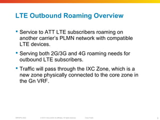
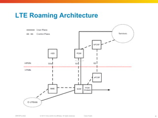
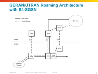
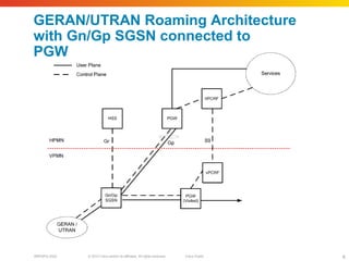
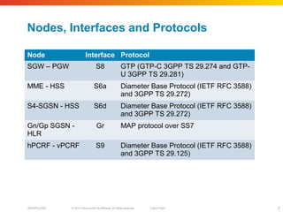
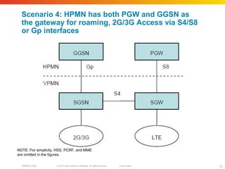
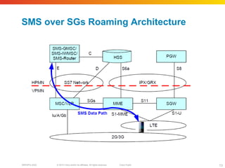
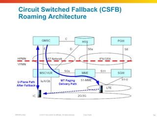
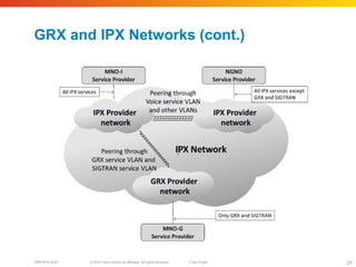
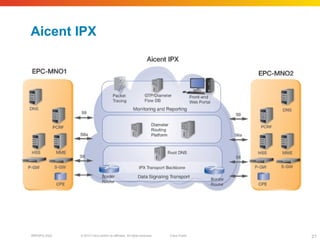
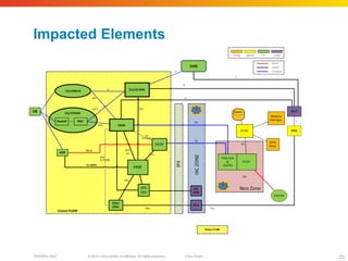
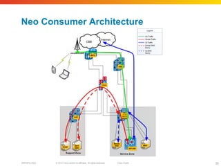
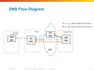
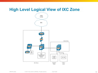
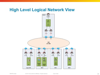
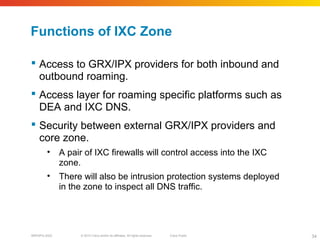
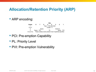
This scenario depicts a case where SGSN has Gp interface towards PGW and SGW has
S8 interface towards PGW. In this scenario, Inter-RAT handover is anchored at PGW.
HPMN may also have GGSN for internal use, but that is not used for roaming in this case.
This scenario depicts a case where SGSN has Gp interface towards PGW and GGSN, and
SGW has S8 interface towards PGW. In this scenario, 2G/3G data access will be provided
over Gp interface, and Inter-RAT handover is anchored at PGW.
The SGSN can select between using GGSN and PGW if the HPMN uses different APNs for
GGSN compared to PGW. If the HPMN uses the same APNs on both GGSN and PGW,
then VPMN SGSN must use UE-capability as follows: If UE is LTE capable, then PGW must
be selected, and if the UE is only 2G/3G capable, GGSN must be selected.
This scenario depicts a case where SGSN has S4 interface towards SGW, and SGW has
S8 interface towards PGW. In this scenario, Inter-RAT handover is anchored at SGW if
SGW doesn't change or PGW if SGW changes. HPMN may also have GGSN for internal
use, but that is not used for roaming in this case.
This scenario depicts a case where SGSN has S4 interface towards SGW and also Gp
interface towards GGSN, and SGW has S8 interface towards PGW. In this scenario, Inter-
RAT handover is anchored at SGW if SGW doesn't change, or PGW if SGW changes.
The SGSN can select between using GGSN and SGW/PGW if the HPMN uses different
APNs for GGSN compared to PGW. If the HPMN uses the same APNs on both GGSN and
PGW, then VPMN SGSN must use UE-capability as follows: If UE is LTE capable, then
SGW/PGW must be selected, and if the UE is only 2G/3G capable, GGSN must be
selected.
SMS over SGs is a means to provide C-Plane based SMS over LTE access without forcing
UE to fall back to overlay 2G/3G accesses. SMS over SGs is defined in 3GPP TS 23.272
[25].
If a VPMN operates a network comprising LTE plus GSM and/or UMTS access(es) and if
this VPMN provides a non-IMS SMS service as well as an LTE data service to visiting
subscribers, then it must support SMS over SGs.
When SMS over SGs is provided for roaming, existing roaming interfaces for SMS services
(E interface) will be used without any changes. Therefore, there are no new guidelines
required for SMS over SGs.
In some initial deployments, there will be no support of voice services on LTE. However,
operators still want users on LTE to access the voice calls. This can be achieved by
providing CSFB procedures. CSFB is defined in 3GPP TS 23.272 [25], in 3GPP TS 23.018
[27], and is introduced as an interim solution before VoLTE is deployed. Release 10
compliant CSFB implementation is recommended for voice fallback as some of Release 8
implementations are not deemed to be efficient enough.
If a VPMN operates a network comprising LTE plus GSM and/or UMTS access(es) and if
this VPMN provides a non-IMS voice service as well as an LTE data service to visiting
subscribers, then it must support CSFB for voice.
During the CSFB procedure, UE camping in LTE will be handed over to overlay 2G/3G
access right after the call request is made. CSFB can be used for voice, Location Services
(LCS) and call-independent supplementary services such as USSD.
When CSFB is provided for roaming, either the Roaming Retry procedure or the Roaming
Forwarding one can be implemented in the VPMN and the HPMN; it may impact the
roaming interfaces.
It is highly recommended to implement one or the other procedure since it increases the
Mobile Terminating Call (MTC) success rate. If the Roaming Retry procedure or the
Roaming Forwarding one is not implemented then the existing roaming interfaces for circuit
switched services will remain unchanged.
The IPX Network was originally conceived as an inter-Service Provider IP backbone created to
carry GTP-tunnels (GPRS Tunnelling Protocol) via the Gp interface between the GPRS Support
Nodes (GSNs) in different GSM Operators that is, data roaming. The Gp interface allowed
mobile end-users to make use of the GPRS/3G services of their home network while roaming in
a visited network. Later, Multimedia Messaging Service (MMS) interworking and Wireless Local
Area Network (WLAN) authentication data roaming were added as supported services. This
original inter-Service Provider IP backbone is in fact an Inter-PLMN (Public Land Mobile Network)
IP Backbone and was termed the GRX. The GRX model is used to interconnect in excess of 300
networks and has proven highly successful.
With the development of IP-based services, interworking of such services has become an industry wide challenge. The GRX model is applicable as an IP interworking solution; however the GRX specification does not meet all the requirements. It has been recognised that by adding interworking specific functionality to the GRX model and offering it to the industry, a common interconnect platform could be established for IP interworking. The enhanced GRX is called an IPX and is designed to support a variety of types of Service Providers in a secure and business sustainable way.
The core enhancements to the GRX are end-to-end Quality of Service and the introduction of the IPX Proxy which facilitates interconnect cascade billing and multi-lateral interconnect agreements.
The IPX introduces the requirement to support Quality of Service features end-to-end. That is, the parties involved in the transport of a service (up to the terminating Service Provider BG/firewall) are bound by end-to-end Service Level Agreements. The GRX service is an exception as this service is offered on IPX on best-effort basis.
A common DNS root database supports domain name resolution. This root database may be used by all IPX parties.
The IPX also introduces IPX Proxy elements. These Proxies may support interworking of specified IP services and make it possible to use cascading interconnect billing and a multilateral interconnect model.
To assist with the translation of Telephone Numbers to URI the common DNS root database of the IPX will support E.164 NUmber Mapping (ENUM) capability.
In the IPX, all user traffic, (that is, User Equipment (UE)-to-UE and UE-to-Server), is separated from Server-to-Server traffic. This is to fulfil the requirement of end users not being able to reach or "explore" the IPX network.
The IPX is isolated from the public Internet and security rules are defined to prevent unintended access to/from it.
IPX Providers should:
Support connections from Service Providers in various ways (Layers 1, 2 and 3).
Comply with IP addressing guidelines for Inter-Service Provider IP Backbone in IR.40.
Comply with DNS guidelines as specified in IR.67.
Offer DNS root service for contracted Service Providers.
Have BGP-4 routing capability.
Per Service Community: distribute all (valid) known routes to Service Providers.
Control which routes a Service Provider can advertise to a Service Community.
Offer interconnectivity to other IPXs (IPX peering).
Comply with Service Level Agreements.
Conform with security requirements laid out in IR.77.
Maintain user traffic separation.
Furthermore, but with the exception of the GRX service, an IPX Provider shall:
Support end-to-end QoS requirements, described in the end-to-end quality SLA and in this document.
Create the agreements required with other IPX Providers to fulfil the end-to-end SLA.
If Diameter Edge Agent is supported in the IPX network, then the IPX Provider must follow IR.88.
Separation of Service Communities on IPX Networks
IPX Provider shall maintain isolation between Service Communities on their IPX Network. This isolation can be logical (for example by VPNs on an IPX Network) or physical (that is, when the Service Provider connects to separate IPX Network, for example for GRX and an IPX Service).
Syniverse and Aicent will deploy a pair of premise routers that will connect via GE to the IXC routers in the IXC zone.
It is anticipated that there will be growth in the number of roaming specific services, especially when LBO is implemented. These service platforms will be connected to the IXC zone.
The IPS signature-matching inspection will be specific to DNS application attacks and exploits.
The Priority-Level AVP (AVP code 1046) is of type Unsigned 32. The AVP is used for deciding whether a bearer establishment or modification request can be accepted or needs to be rejected in case of resource limitations (typically used for admission control of GBR traffic). The AVP can also be used to decide which existing bearers to pre-empt during resource limitations. The priority level defines the relative importance of a resource request.
Values 1 to 15 are defined, with value 1 as the highest level of priority.
Values 1 to 8 should only be assigned for services that are authorized to receive prioritized treatment within an operator domain. Values 9 to 15 may be assigned to resources that are authorized by the home network and thus applicable when a UE is roaming.
The Pre-emption-Capability AVP (AVP code 1047) is of type Enumerated. If it is provided within the QoS-Information AVP, the AVP defines whether a service data flow can get resources that were already assigned to another service data flow with a lower priority level. If it is provided within the Default-EPS-Bearer-QoS AVP, the AVP defines whether the default bearer can get resources that were already assigned to another bearer with a lower priority level.
The following values are defined:
PRE-EMPTION_CAPABILITY_ENABLED (0)
This value indicates that the service data flow or bearer is allowed to get resources that were already assigned to another service data flow or bearer with a lower priority level.
PRE-EMPTION_CAPABILITY_DISABLED (1)
This value indicates that the service data flow or bearer is not allowed to get resources that were already assigned to another service data flow or bearer with a lower priority level. This is the default value applicable if this AVP is not supplied.
The Default-EPS-Bearer-QoS AVP (AVP code 1049) is of type Grouped, and it defines the QoS information for the EPS default bearer. When this AVP is sent from the PCEF to the PCRF, it indicates the subscribed QoS for the default EPS bearer and/or the retained QoS for the default EPS bearer in the PCEF. When this AVP is sent from the PCRF to the PCEF, it indicates the authorized QoS for the default EPS bearer.
The QoS class identifier identifies a set of IP-CAN specific QoS parameters that define QoS, excluding the applicable bitrates and ARP. When included in the Default-EPS-Bearer-QoS AVP, it shall include only non-GBR values.
The Allocation-Retention-Priority AVP is an indicator of the priority of allocation and retention for the default bearer.
AVP Format:
Default-EPS-Bearer-QoS::= < AVP Header: 1049 >
[ QoS-Class-Identifier ]
[ Allocation-Retention-Priority]
* [ AVP ]
The Pre-emption Vulnerability AVP (AVP code 1048) is of type Enumerated. If it is provided within the QoS-Information AVP, the AVP defines whether a service data flow can lose the resources assigned to it in order to admit a service data flow with higher priority level. If it is provided within the Default-EPS-Bearer-QoS AVP, the AVP defines whether the default bearer can lose the resources assigned to it in order to admit a pre-emption capable bearer with a higher priority level.
The following values are defined:
PRE-EMPTION_VULNERABILITY_ENABLED (0)
This value indicates that the resources assigned to the service data flow or bearer can be pre-empted and allocated to a service data flow or bearer with a higher priority level. This is the default value applicable if this AVP is not supplied.
PRE-EMPTION_VULNERABILITY_DISABLED (1)
This value indicates that the resources assigned to the service data flow or bearer shall not be pre-empted and allocated to a service data flow or bearer with a higher priority level.
The goal of standardizing a QCI with corresponding characteristics is to ensure that applications / services mapped to that QCI receive the same minimum level of QoS in multi-vendor network deployments and in case of roaming.
The ARP priority levels 1-8 should only be assigned to resources for services that are authorized to receive prioritized treatment within an operator domain (i.e. that are authorized by the serving network). The ARP priority levels 9-15 may be assigned to resources that are authorized by the home network and thus applicable when a UE is roaming.
NOTE:This ensures that future releases may use ARP priority level 1-8 to indicate e.g. emergency and other priority services within an operator domain in a backward compatible manner. This does not prevent the use of ARP priority level 1-8 in roaming situation in case appropriate roaming agreements exist that ensure a compatible use of these priority levels.
The APR dictates whether a bearer establishment/modification request can be accepted or rejected in the event of conflicts in demand for network resources. At the time of exceptional network resources limitations, such as handover, ARP can be used by the eNodeB to drop a flow with a lower ARP to free up capacity. ARP, however, has no effect on the network treatment received by the flow once the flow is successfully established.