
Recommended
More Related Content
What's hot
What's hot (20)
Similar to Gis ppt (gas insulated sub station) deepak kumar kannaujiya,
Similar to Gis ppt (gas insulated sub station) deepak kumar kannaujiya, (20)
Recently uploaded
Recently uploaded (20)
Gis ppt (gas insulated sub station) deepak kumar kannaujiya,
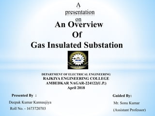
- 1. A presentation on An Overview Of Gas Insulated Substation DEPARTMENT OF ELECTRICAL ENGINEERING RAJKIYA ENGINEERING COLLEGE AMBEDKAR NAGAR-224122(U.P.) April 2018 Presented By : Guided By: Deepak Kumar Kannaujiya Roll No. - 1673720703 Mr. Sonu Kumar (Assistant Professor)
- 2. 2 Contents: Introduction Conventional substations (AIS) Limitations of AIS The need for GIS Introduction to GIS Properties of SF6 GIS Equipment's GIS assembly Advantages of GIS Demerits of GIS Future trends in GIS Conclusion References
- 3. 3 Introduction Gas Insulated Substation (GIS) is a compact, multicomponent assembly enclosed in a ground metallic housing in which the primary insulating medium is compressed SF6 gas. The compactness is with the use of SF6 gas, which has high dielectric strength. Gas Insulated Substations (GIS) can be used for longer times without any periodical inspections.
- 4. 4 AIS-Air Insulated Substation Air used as a dielectric. Normally used for outdoor substations. In very few cases used for indoor substations. Easy to expand (in case that space is not an issue) Excellent overview, simple handling and easy access. 4
- 5. 5 Limitations of AIS: Large dimensions due to statutory clearances and poor dielectric strength of air. Insulation deterioration with ambient conditions and susceptibility to pollutants. Wastage of space. Life of steel structures degrades. Seismic instability. Large planning & execution time. Regular maintenance of the substation required.
- 6. 6 GIS Benefits over AIS
- 7. 7 The need for G.I.S: Non availability of sufficient space. Difficult climatic and seismic conditions at site. Urban site (high rise building). High altitudes. Limitations of AIS.
- 8. 8 Gas Insulated Substation: Introduction: Compact, multi-component assembly. Enclosed in a ground metallic housing. Sulphur Hexafluoride (SF6) gas the primary insulating medium. (SF6) gas is superior dielectric properties used at moderate pressure for phase to phase and phase to ground insulation Preferred for voltage ratings of 72.5 kV, 145 kV, 300 kV and 420 kV and above. Various equipment's like Circuit Breakers, Bus-Bars, Isolators, Load Break Switches, Current Transformers, Voltage Transformers, Earthing Switches, etc. housed in metal enclosed modules filled with SF6 gas.
- 9. 9 Properties of SF6: Characteristics SF6 is colorlessly, odorless and a chemical neutral (inert) gas. SF6 is 5x heavier than air, is not toxic and has no dangerous components inside. SF6 is no hazardous material. SF6 has no eco-toxic potential. SF6 has no impact for the ozonosphere. Advantages for use in GIS The dielectric strength of SF6 gas at atmospheric pressure is approximately three times that of air. It is incombustible, non toxic, colorless and chemically inert. It has arc-quenching properties 3 to 4 times better than air at equal pressure.
- 10. 10 GIS Equipment's Circuit Breaker Current transformer Voltage transformer Feeder Disconnector and Earthing switch Bus bar Gas density Monitor
- 11. 72.5 kv GIS assembly 11
- 12. 12 Bus Bar To connect GIS modules that are not directly connected to each other, an SF6 bus consisting of an inner conductor and outer enclosure is used. The conductors made of aluminum or copper, depending on the current rating, are supported by gas tight insulator (for standard bay bus) or individual supporting insulators (for extended bus). 12
- 13. 13 Current Transformer The secondary windings are designed for metering or protection purposes. One terminal of each used secondary winding and one terminal of unused winding have to be earthed during the transformer operation (unused short- circuited also).
- 14. 14 Technical Parameters Of CT Technical parameters of CT Value Enclosure Single / separate phase wise Enclosure material Aluminum Alloy Rated voltage 72.5 KV/420 KV Metering(66kv) 600-300 / 1A Metering(400kv) 3000-2000-1000-500/1A
- 15. 15 Potential Transformer It is used for protection and measuring. They are based on the electromagnetic transformer principle, where primary and secondary winding galvanically separated from one another. Primary winding is wound on the top of the core and the secondary winding. The letter are connected to the terminals in the external terminal box through a gas-tight multiple bushing. Utilization of Sf6 gas as insulating medium, together with plastic foil in the winding. 15
- 16. Technical Parameters Of PT Enclosure Single / separate phase wise Enclosure material Aluminum Alloy Rated voltage 72.5 KV/420 KV Metering 66KV/110V Metering 400KV/110V 16
- 17. Transformer Gas insulated transformers, using incombustible SF6 gas as a insulation and cooling medium, enable to remove a fire fighting equipment from transformer room. Since gas insulated transformer does not need the conservator, the height of transformer room can be reduced. 17
- 18. Parameters Of Transformer Technical particulars 500 kV System 230 kV System 110 kV System Rated Voltage 550 kV (rms) 245 kV (rms) 145 kv (rms) Rated frequency 50 Hz 50 Hz 50 Hz Grounding Effectively Effectively Effectively earthed earthed earthed Rated current 4000A 3150A 2000A 18
- 19. Circuit Breaker A circuit breaker is an automatically operated electrical switch designed to protect an electrical circuit from damage caused by excess current from an overload or short circuit. Circuit breaker is of the single pressure type ,during interruption a compression piston in the chamber generates the gas pressure required to extinguish the arc between the contacts. Maintenance free up to 2000 times load breaking. Mechanically type tested for 10000 operations. 19
- 20. Technical Parameters Of CB Technical parameters of CT Value Particulars 66 kV/400 kV Enclosure Single / separate phase wise Enclosure material Aluminum Alloy Rated voltage 72.5 kV/420 kV Rated current 1600A/3150A Rated frequency 50 Hz Rated short-circuit breaking current 25 kA/40 kA rms Duration 3 sec Type of operating mechanism for CB Spring /combined 20
- 21. Disconnectors and Earthing Switches Disconnectors and earthing switches are often offered as a combination of both. The disconnector has a switching capability of bus-transfer current, small capacitive current as bus charging and small inductive current as transformer magnetizing current, if required. The task of an earthing switch is to earth de-energised parts of the switchgear and – in the case of multi-pole earthing switches – to short-circuit them at the same time. Disconnectors and earthing switches are normally motor or manual-operated. 21
- 22. Technical parameters of Disconnectors Particulars Parameters Enclosure Single/separate phase wise Enclosure material Aluminum Alloy Rated voltage 72.5 / 420 kV Rated current 1600 /3150 A Rated short-time current 25/ 40 kA rms Duration 3 sec Rated control and operating voltage 110/220 V DC Type of operating mechanism Motor operated 22
- 23. Technical Parameters Of Earthing Switch Technical parameters of E S Value Particulars 66kV/400kV Enclosure Single/separate phase wise Enclosure material Aluminum Alloy Rated voltage 72.5 /420 kV Rated short-time current 25/ 40 kA rms, 3 sec Rated peak withstand current 62.5 /100 kA peak Type of operating mechanism Motor operated 23
- 24. Gas Density Monitor Directly mounted on the enclosure. In case of gas leakage a micro-switch is actuated. • Thresholds for refilling (first stage). • lock-out alarm(second stage). 24
- 25. Demerits of GIS High cost compared to conventional outdoor sub-station. Excessive damage in case of internal fault. Long outage periods as repair of damaged part at site may be difficult. Requirements of cleanliness are very stringent. Dust or moisture can cause internal flashovers. Such sub-stations generally indoor. They need a separate building. This is generally not required for conventional outdoor sub-stations. Procurement of gas and supply of gas to site is problematic. Adequate stock of gas must be maintained. 25
- 26. Advantages of GIS Occupies very less space (1/10th) compared to ordinary substations. Hence, most preferred where area for substation is small (e.g. Cities) Most reliable compared to Air Insulated Substations. Number of outages due to the fault is less. Maintenance Free. Can be assembled at workshop and modules can be commissioned in the plant easily. 26
- 27. 27 Future Trends: Compact design of switch gear by using three phase modules. Use of vacuum circuit breaker cells in the medium high voltage GIS. Optimization of GIS design to allow easier maintenance. Development of DC GIS for incorporating into expanding national/international HVDC systems. Search for replacement gases for SF6. The most promising - an 80%/20% N2/SF6 mixture. Replacement of existing AIS by GIS will accelerate especially near urban centers.
- 28. 28 Conclusion: GIS – necessary for Extra HV & Ultra HV Some important areas to be studied include: More conservative design. Improved gas handling. Decomposition product management techniques. Achieving & maintaining high levels of availability require – more integrated approach to quality control by both users and manufactures.
- 29. References E. Mikes, H. Aeschbach et al. "Innovative GIS based solutions for substations" CIGRE SC23 Colloquium Venezuela, Paper 3.1, 2001. Hermann Koch “Gas Insulated Substations” Library Of Congress Cataloging-in-publication 2014 M.Bilal Latif “ Comparison of GIS substation over conventional substation “ , IEEE A. Edlinger, G. Mauthe, F. Pinekamp, D. Schlicht, W. Schmidt ,Disconnector switching of charging currents in metal-enclosed SF6-gas insulated switchgear at EHV, 1984. R. Witzman, "modelling of different GIS component", V Int. Symp. on HV Eng., 1987-Aug.-23-28. 29
- 30. 30