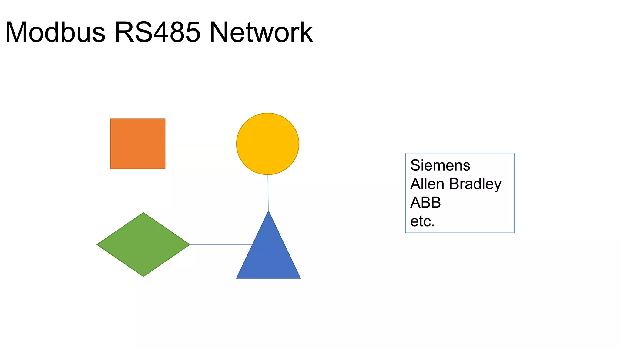
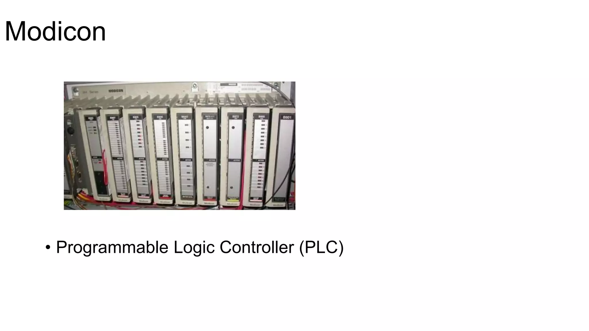
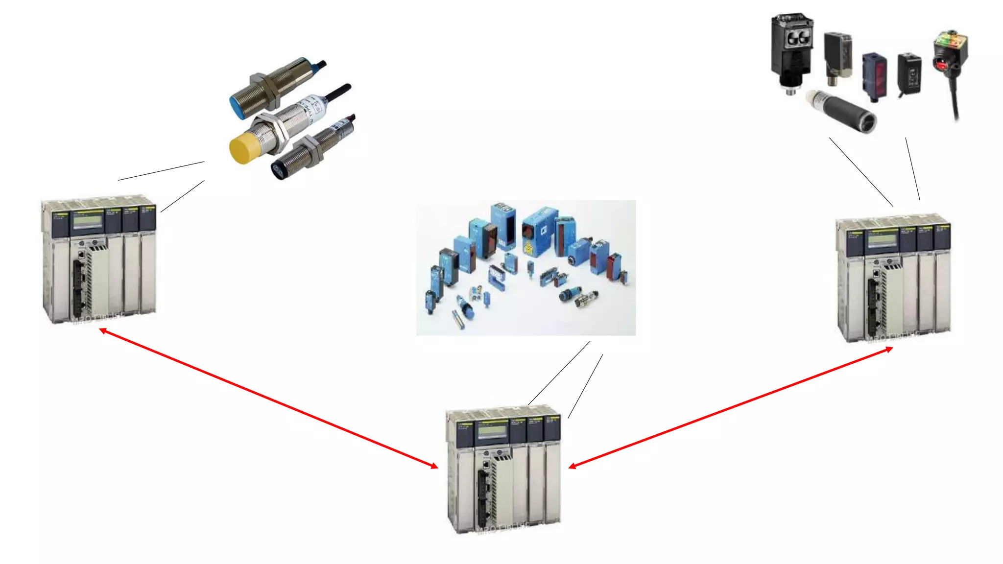
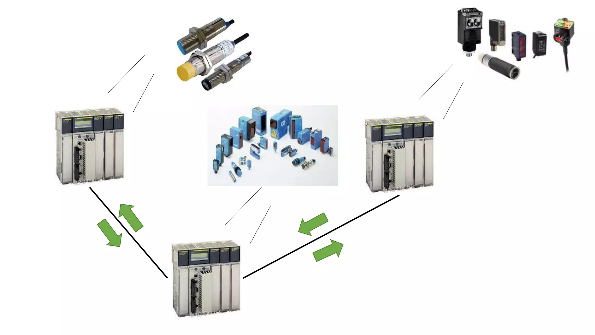
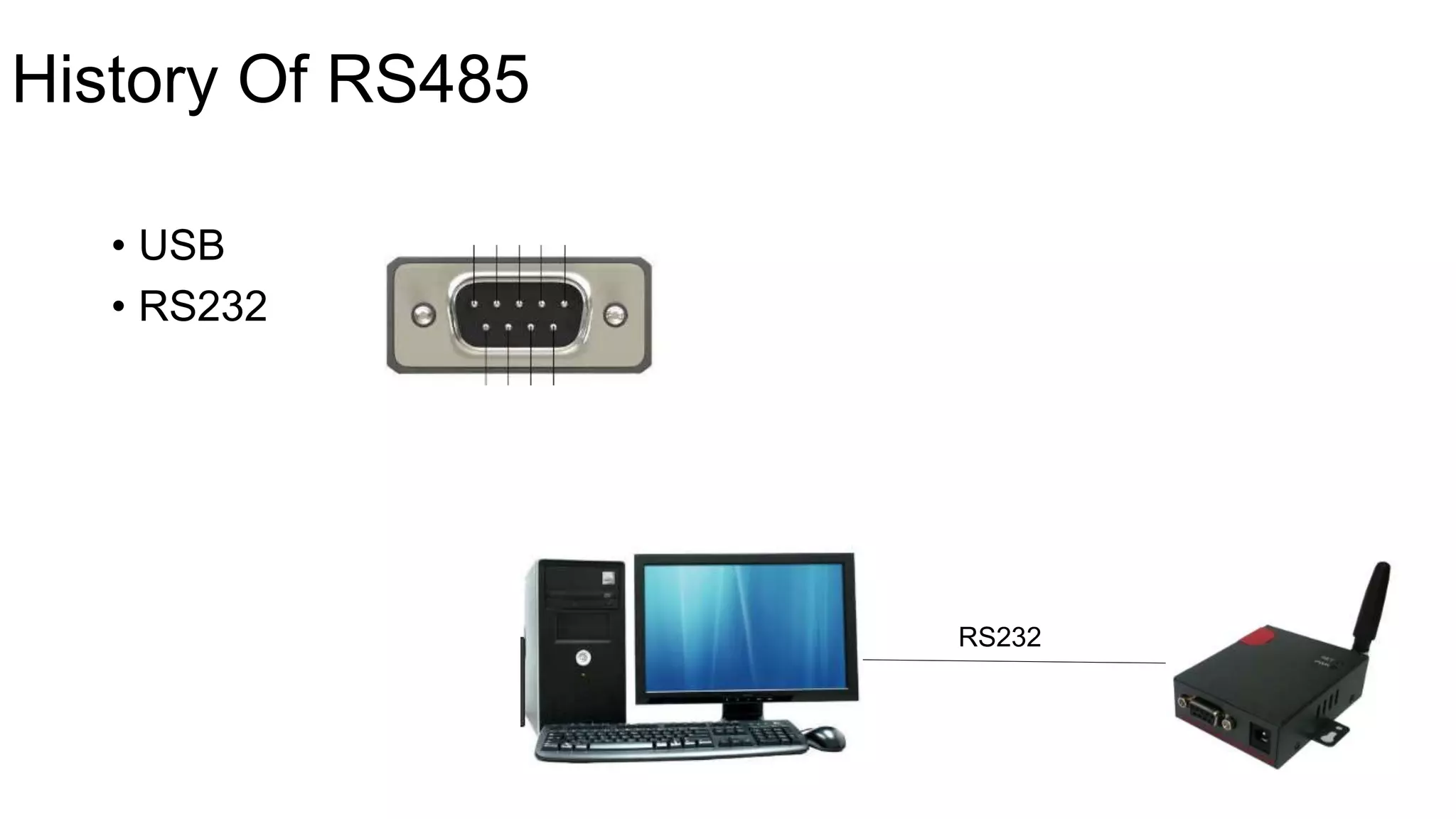
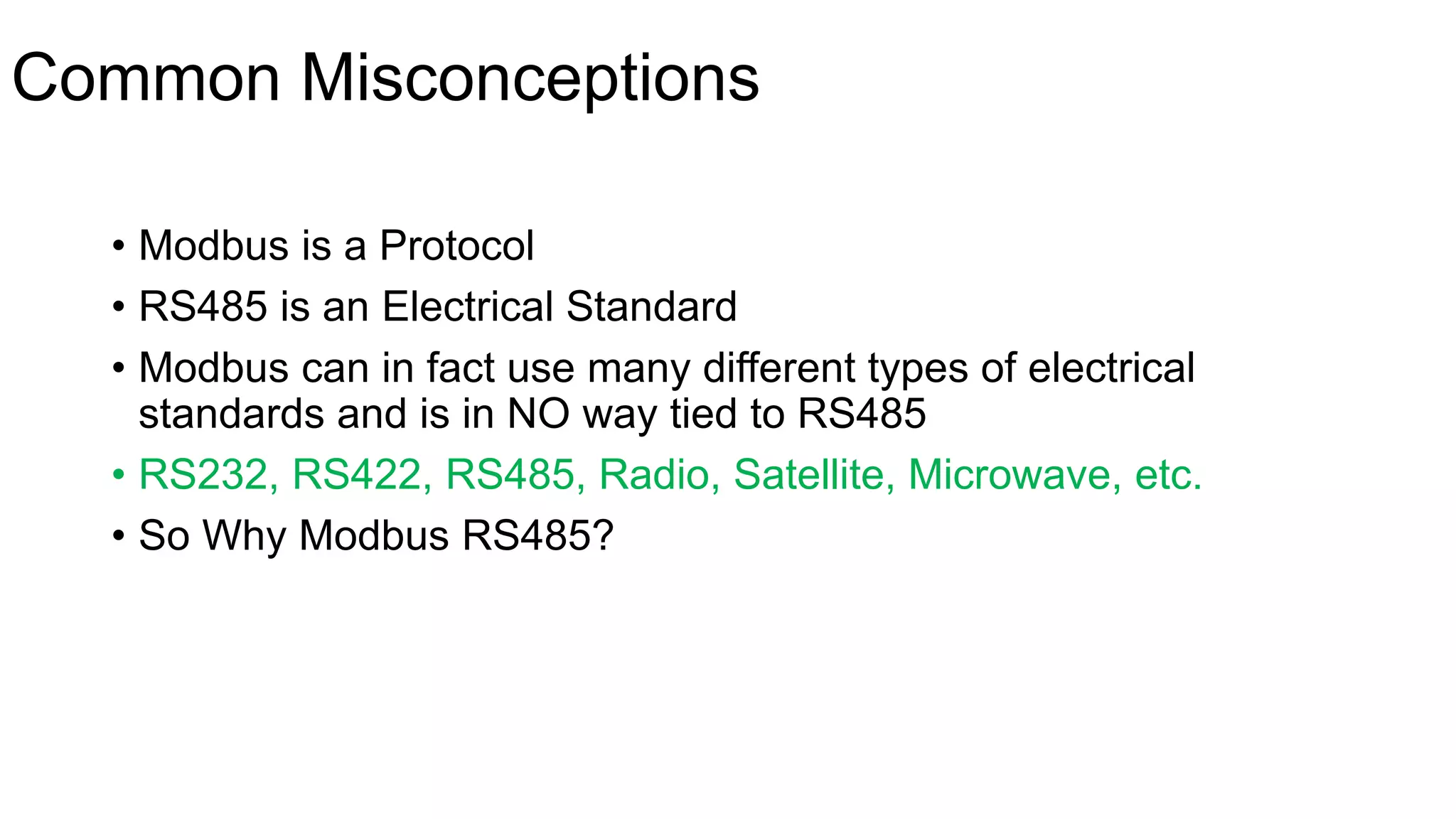
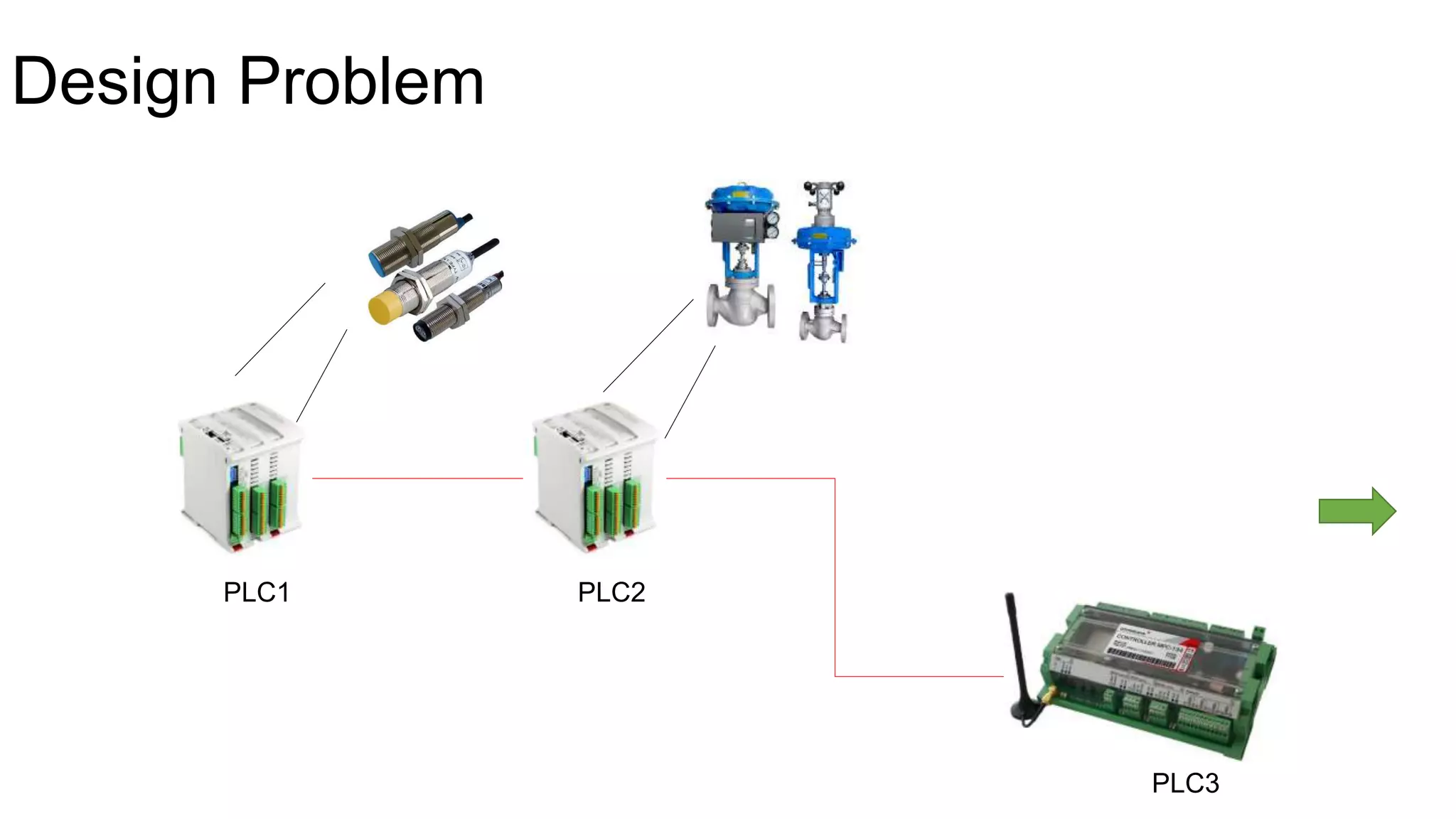
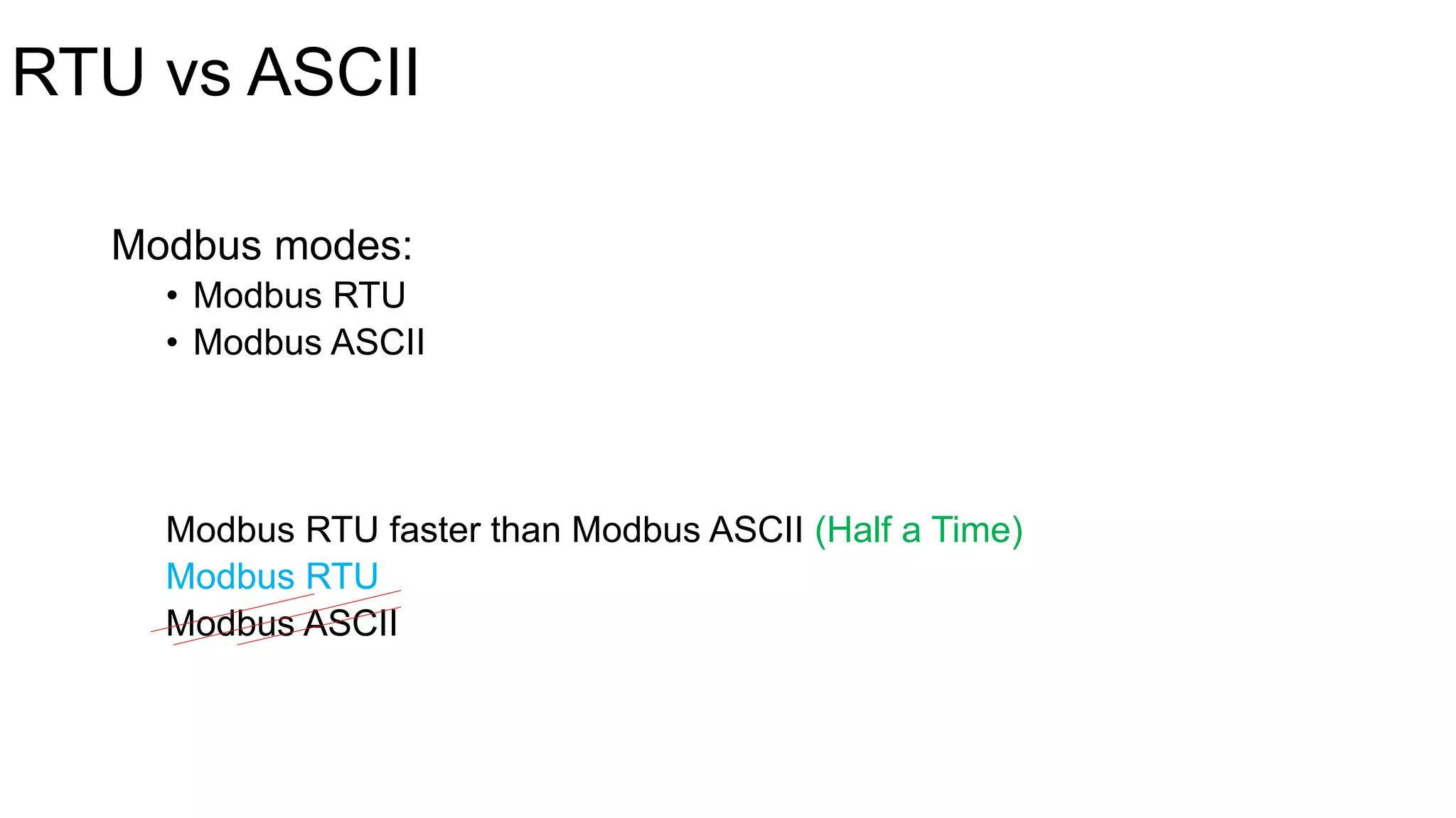
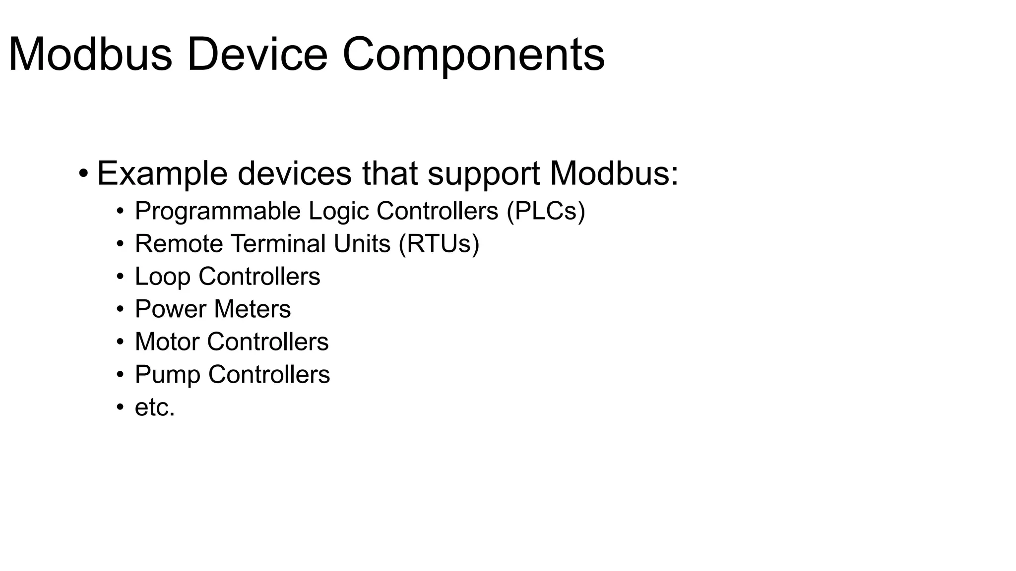
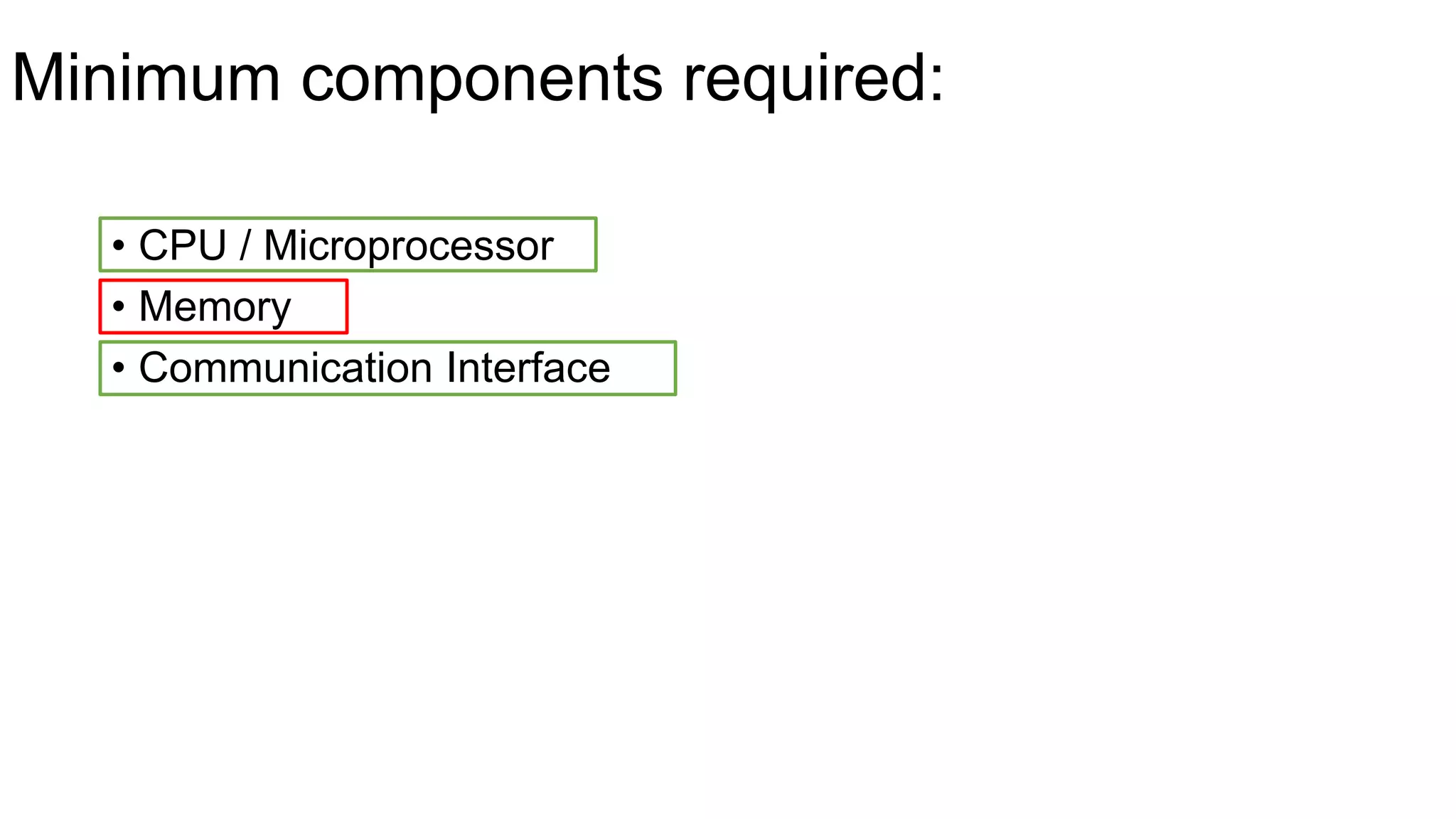
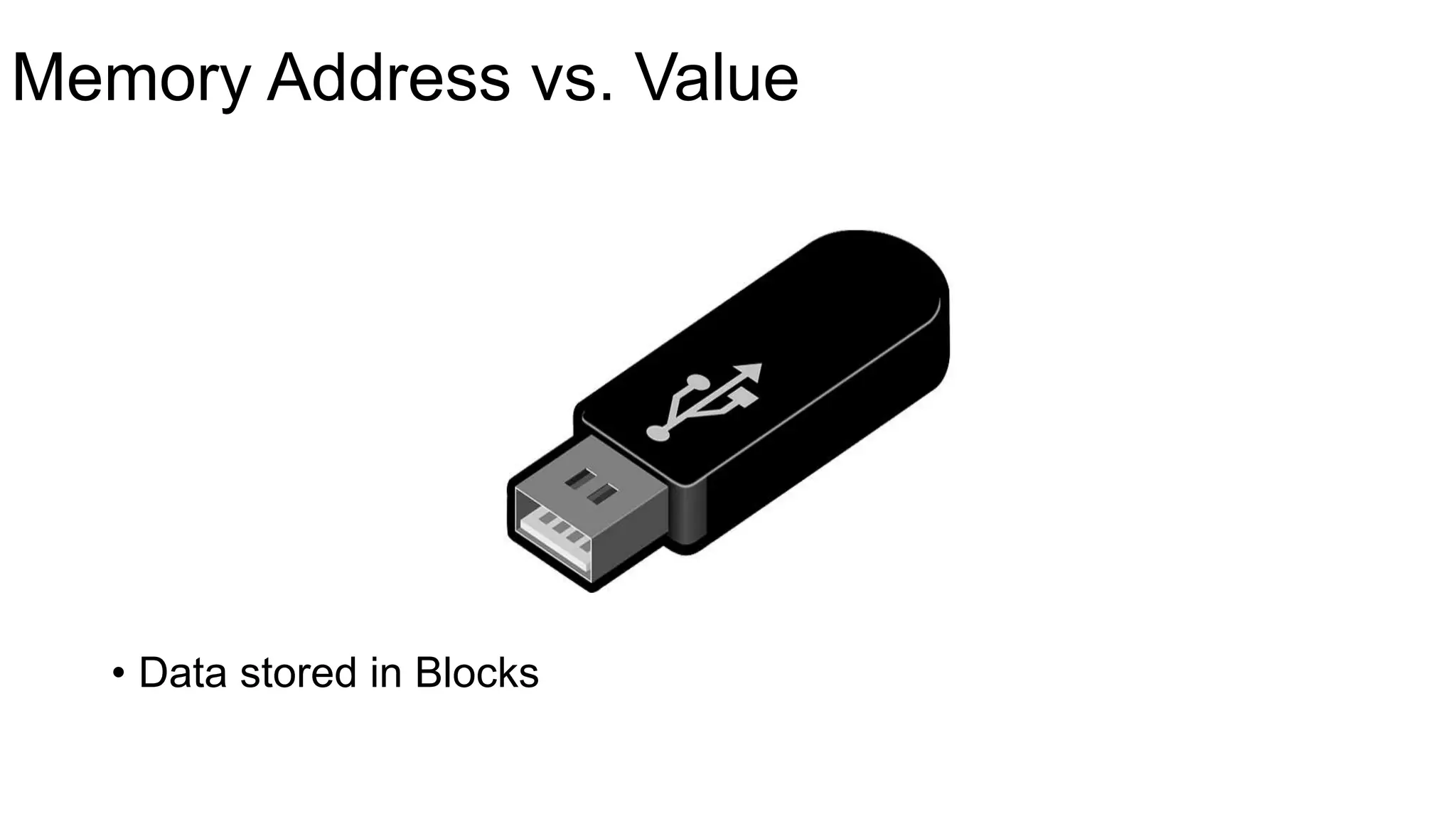
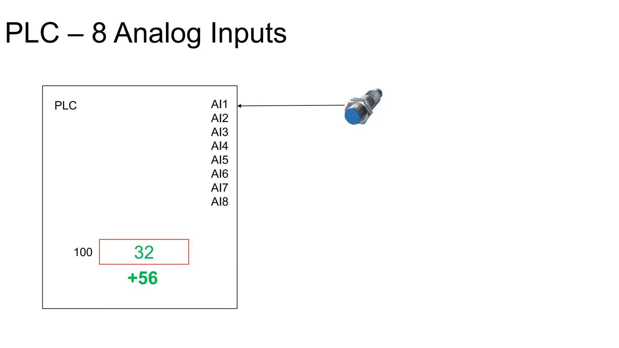
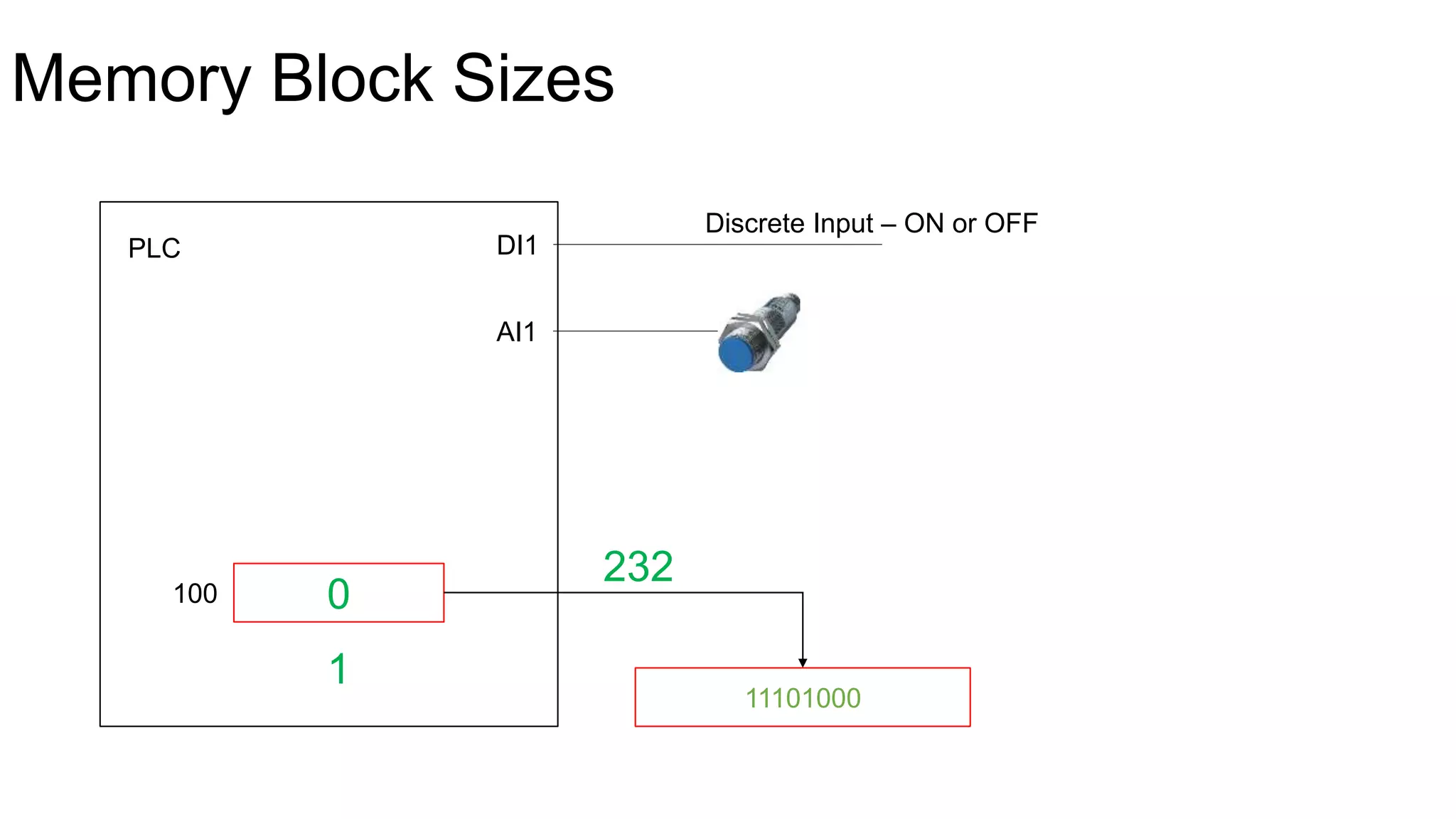
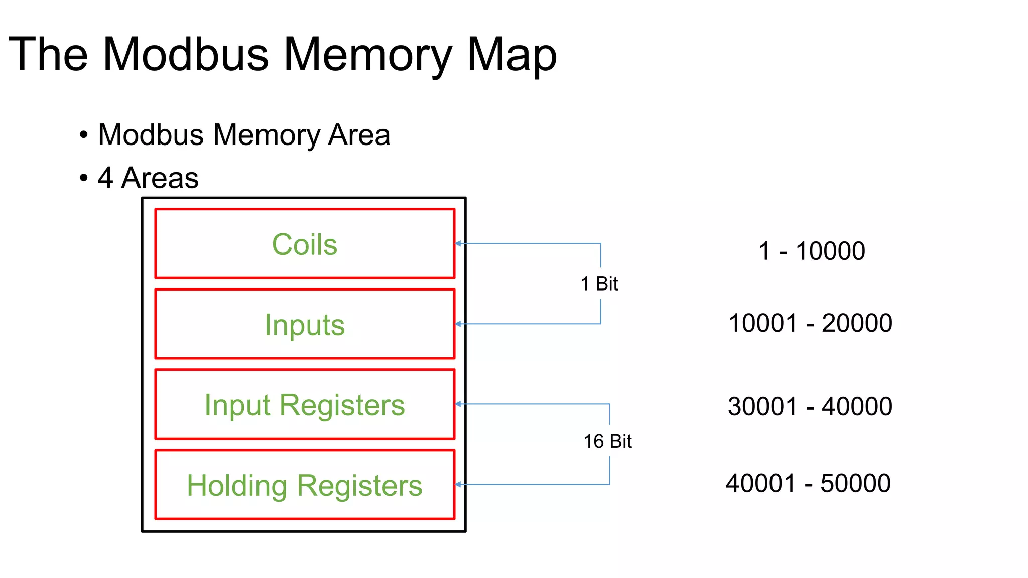
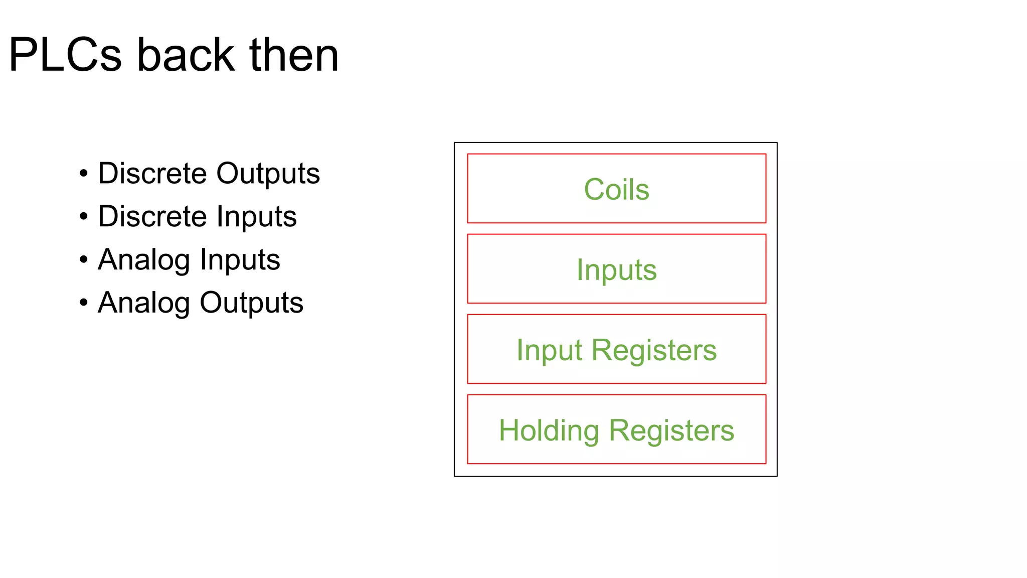
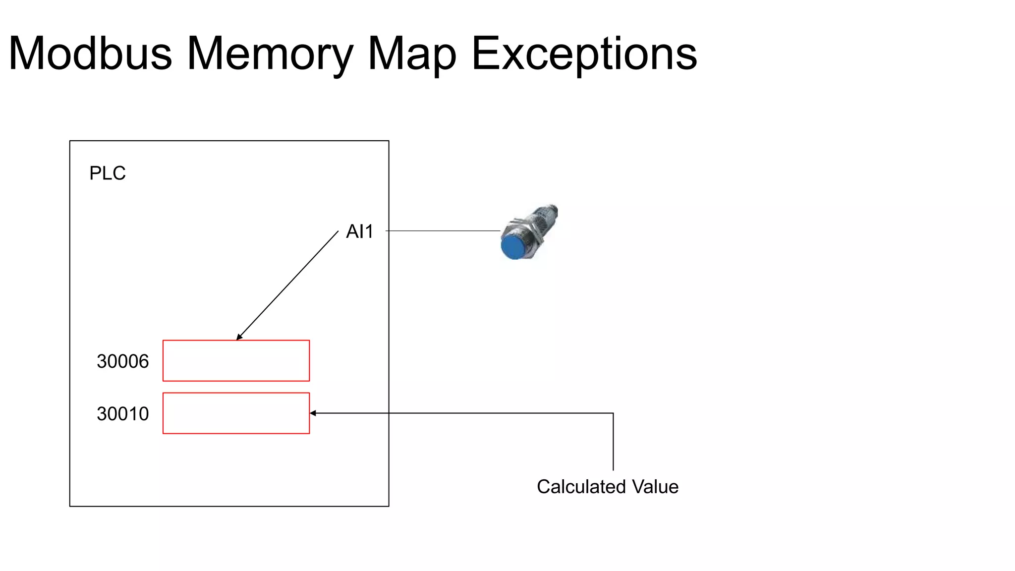
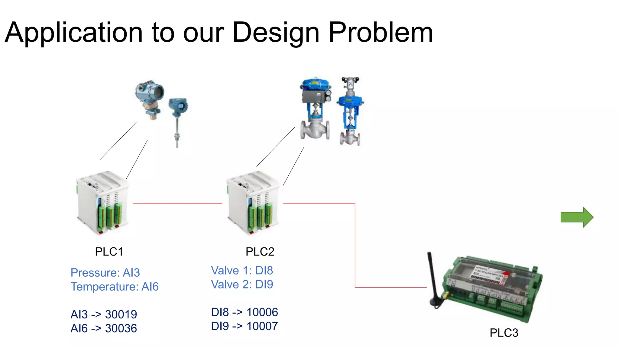
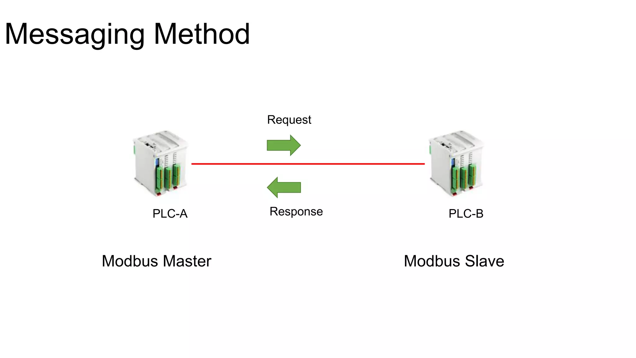
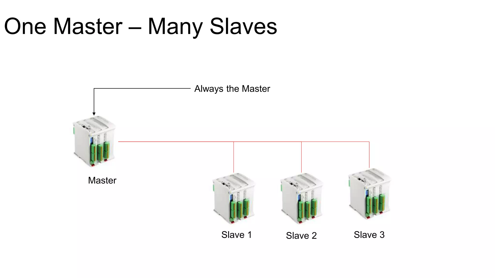
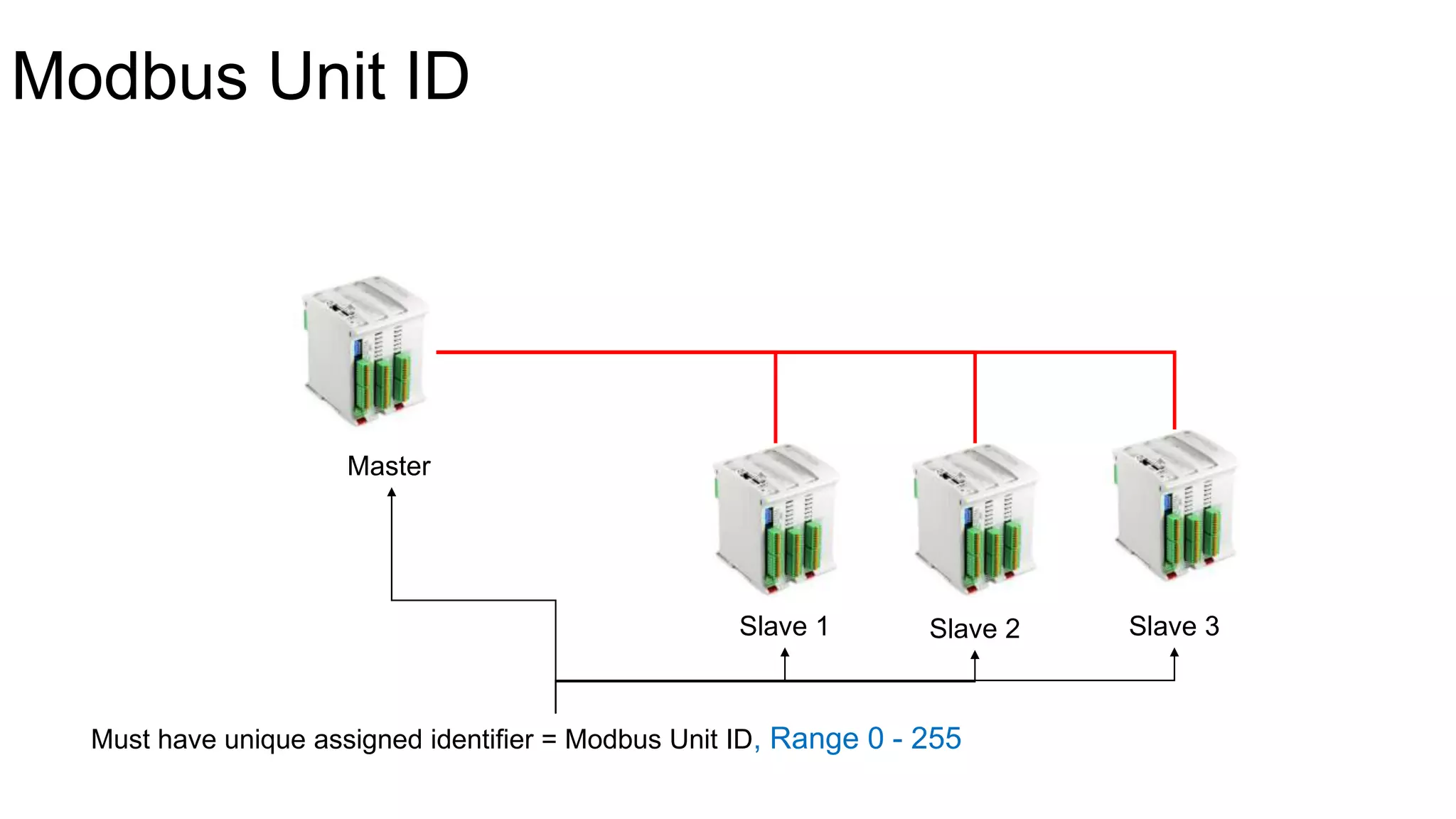
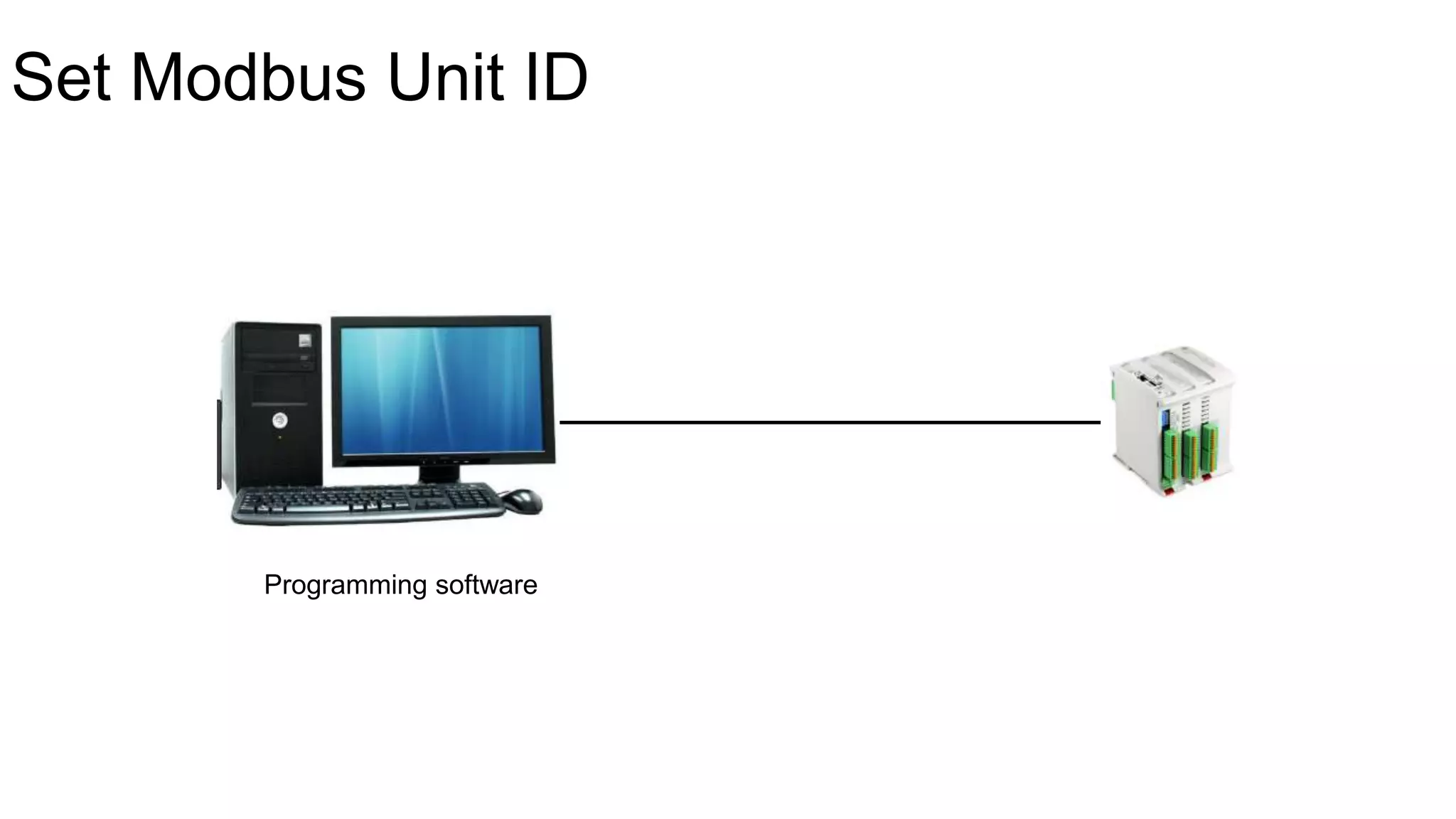
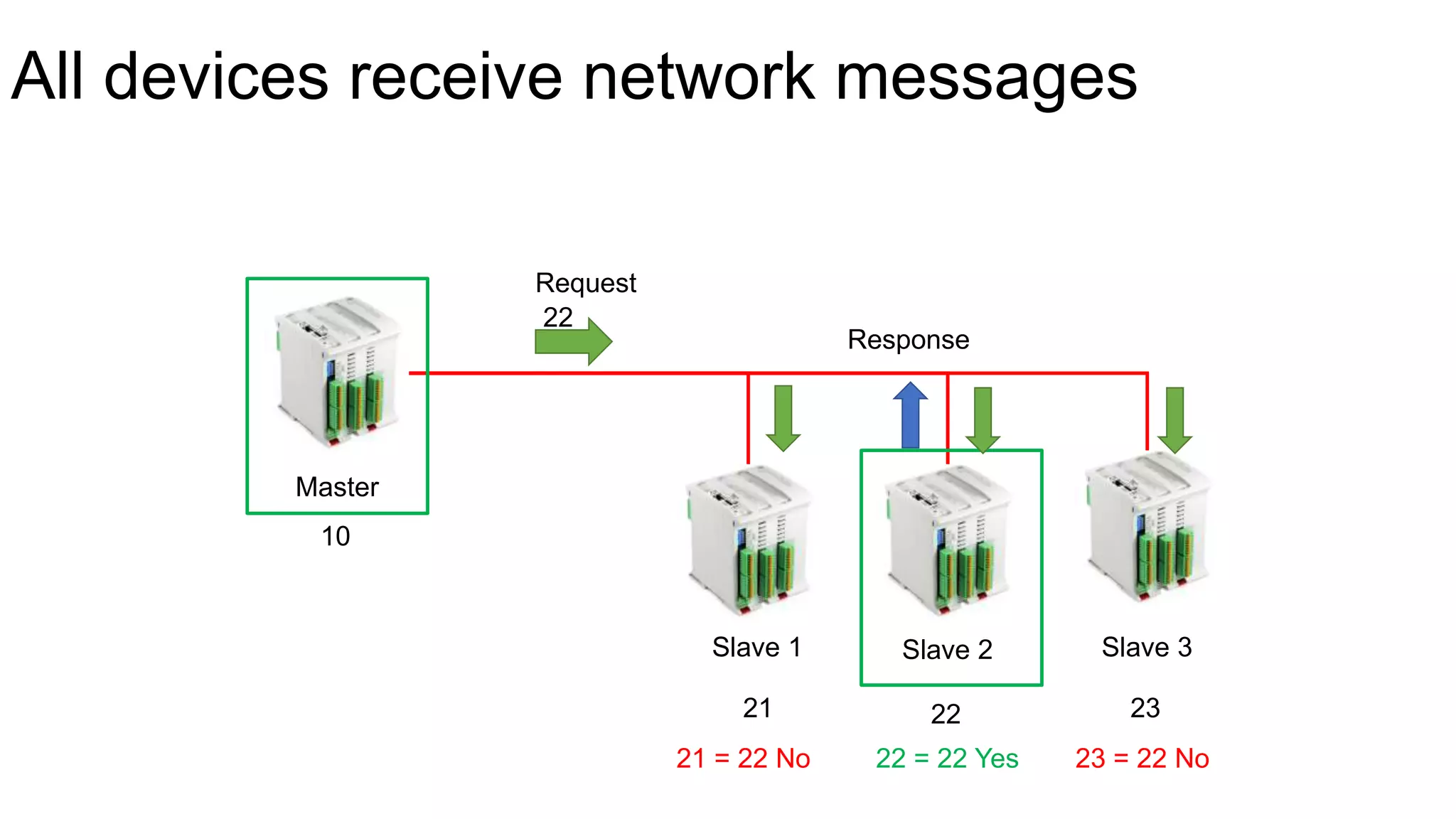
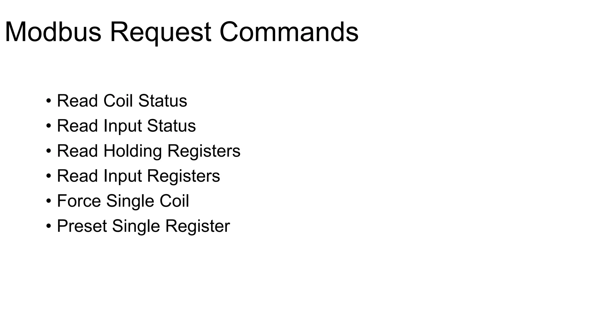
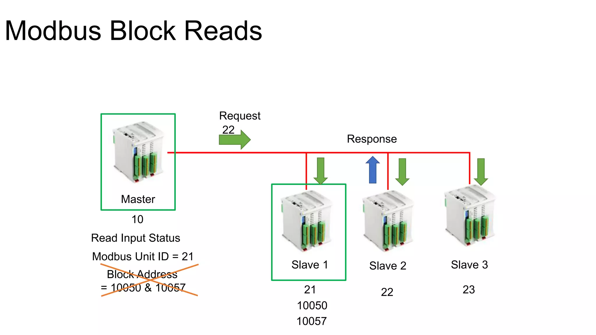
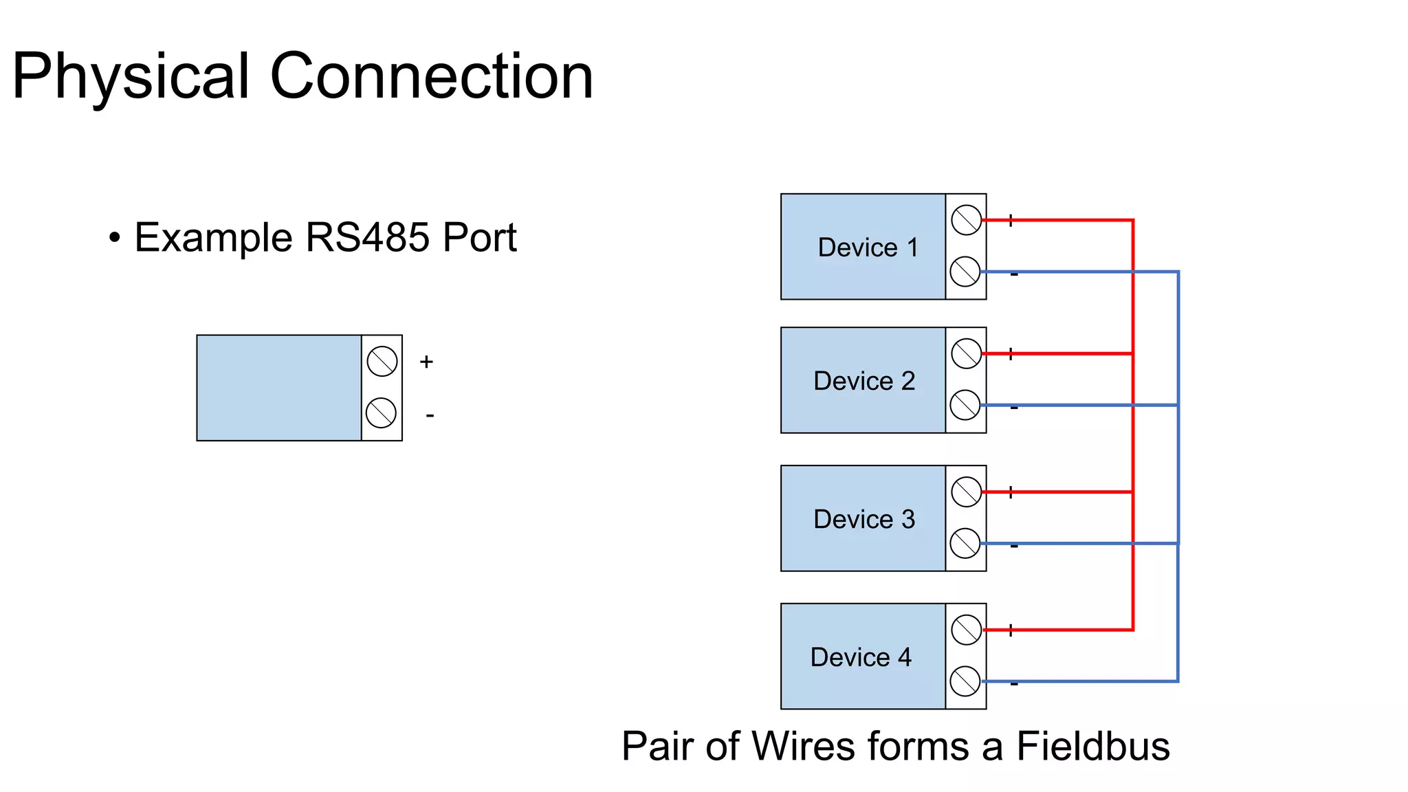
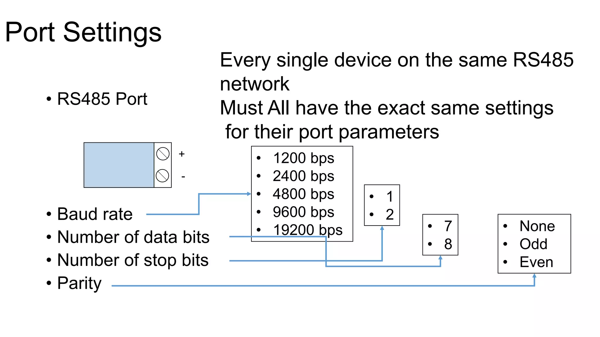
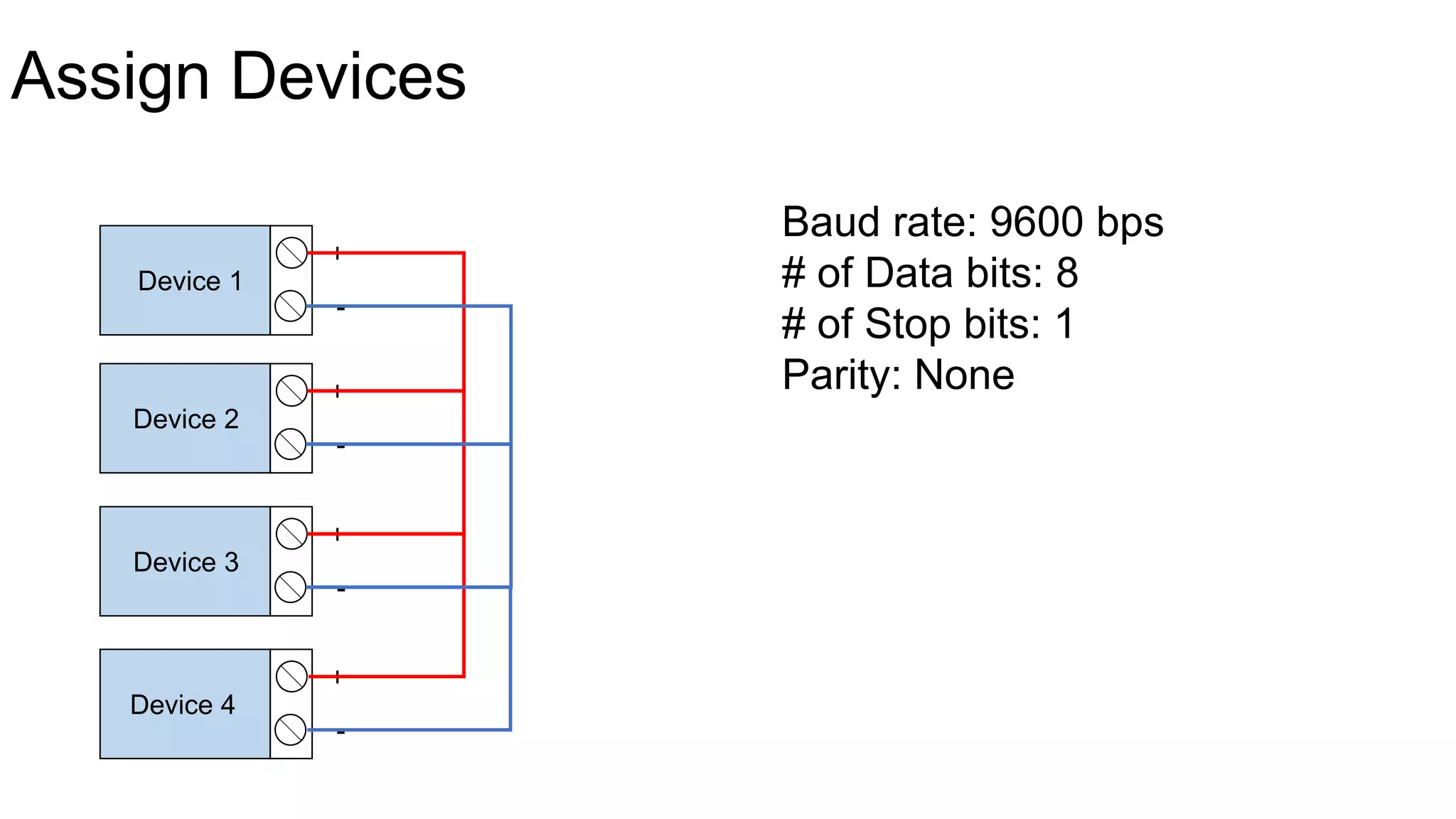
Modbus RS485
In One Video
Saif Ali
Modbus RS485 Network
Siemens
Allen Bradley
ABB
etc.
Modbus
• Still Most Popular Protocol
• Most Supported
• Theoretical and Practical
• Modbus RS485
• Marketable and Valuable
History of Modbus Protocol
• Distributed Control System (DCS)
Expensive to Purchase & Maintain
Lots of Cabling
High Maintenance
Modicon
• Programmable Logic Controller (PLC)
1979
• Modbus
• Modicon + Fieldbus = Modbus
Modbus
• FREE Open Standard
• Rapidly Adopted
• Many Different Manufacturers
History Of RS485
• USB
• RS232
RS232
RS232 Drawbacks
• Point-to-Point Standard Only
• Limited Distance - 50 Feet
• Susceptible to Electrical Noise
RS485 Features
• Point-to-Multipoint – Up to 32 Devices without Repeater
• 4000 feet
• Very Resistant to Electrical Noise
Common Misconceptions
• Modbus is a Protocol
• RS485 is an Electrical Standard
• Modbus can in fact use many different types of electrical
standards and is in NO way tied to RS485
• RS232, RS422, RS485, Radio, Satellite, Microwave, etc.
• So Why Modbus RS485?
Design Problem
PLC1 PLC2
PLC3
RTU vs ASCII
Modbus modes:
• Modbus RTU
• Modbus ASCII
Modbus RTU faster than Modbus ASCII (Half a Time)
Modbus RTU
Modbus ASCII
Modbus Device Components
• Example devices that support Modbus:
• Programmable Logic Controllers (PLCs)
• Remote Terminal Units (RTUs)
• Loop Controllers
• Power Meters
• Motor Controllers
• Pump Controllers
• etc.
Minimum components required:
• CPU / Microprocessor
• Memory
• Communication Interface
Memory Address vs. Value
• Data stored in Blocks
Memory Block
Memory Address
Memory Value
PLC – 8 Analog Inputs
PLC AI1
AI2
AI3
AI4
AI5
AI6
AI7
AI8
32100
+56
Memory Block Sizes
• Memory Sizes
• For Different Purposes
• Measured in Bits
• Bits = Binary + Digit >>> Can be 0 or 1
• More Bits = Higher Number
• 1 Bit
• 8 Bit
• 16 Bit
• 32 Bit
Memory Block Sizes
PLC DI1
Discrete Input – ON or OFF
0100
AI1
11101000
1
232
The Modbus Memory Map
• Modbus Memory Area
• 4 Areas
Coils
Inputs
Input Registers
Holding Registers
1 Bit
16 Bit
1 - 10000
10001 - 20000
30001 - 40000
40001 - 50000
PLCs back then
• Discrete Outputs
• Discrete Inputs
• Analog Inputs
• Analog Outputs
Coils
Inputs
Input Registers
Holding Registers
Modbus Memory Map Exceptions
PLC
AI1
30010
30006
Calculated Value
Determining I/O Mapping to Memory
PLC AI1
AI2
AI3
AI4
AI5
AI6
AI7
AI8
30007
31008
30020
Application to our Design Problem
PLC1 PLC2
PLC3
Pressure: AI3
Temperature: AI6
AI3 -> 30019
AI6 -> 30036
Valve 1: DI8
Valve 2: DI9
DI8 -> 10006
DI9 -> 10007
Messaging Method
PLC-A PLC-B
Request
Response
Modbus Master Modbus Slave
One Master – Many Slaves
Master
Slave 1 Slave 2 Slave 3
Always the Master
Modbus Unit ID
Master
Slave 1 Slave 2 Slave 3
Must have unique assigned identifier = Modbus Unit ID, Range 0 - 255
Set Modbus Unit ID
Programming software
All devices receive network messages
Master
Slave 1 Slave 2 Slave 3
10
21 22 23
Request
22
21 = 22 No 23 = 22 No22 = 22 Yes
Response
Modbus Request Commands
• Read Coil Status
• Read Input Status
• Read Holding Registers
• Read Input Registers
• Force Single Coil
• Preset Single Register
Modbus Block Reads
Master
Slave 1 Slave 2 Slave 3
10
21 23
Request
22
Response
22
10050
10057
Read Input Status
Modbus Unit ID = 21
Block Address
= 10050 & 10057
Modbus Block Reads
Master Slave 1
10050
10051
10052
10053
10054
10055
10056
10057
Read Input Status
Modbus Unit ID = 21
Start Address = 10050
Number of Blocks (length) = 8
Application to our Design Problem
PLC1 PLC2
PLC3
Master
Slave Slave
Pressure: 30019
Temperature: 30036
Valve 1: 10006
Valve 2: 10007
22 21
10
Read Commands
• PLC 2 – Memory blocks 10006 and 10007
• Read Input Status
• Modbus Unit ID = 21
• Start Memory blocks address = 10006
• Number of blocks = 2
Read Commands
• PLC 1 – Memory blocks 30019 and 30036
• Request #1
• Read Input Registers
• Modbus Unit ID = 22
• Start Memory blocks address = 30019
• Number of blocks = 1
• Request #2
• Read Input Registers
• Modbus Unit ID = 22
• Start Memory blocks address = 30036
• Number of blocks = 1
Physical Connection
• Example RS485 Port
+
-
+
-
+
-
+
-
+
-
Device 1
Device 2
Device 3
Device 4
Pair of Wires forms a Fieldbus
Port Settings
• RS485 Port
• Baud rate
• Number of data bits
• Number of stop bits
• Parity
+
-
Every single device on the same RS485
network
Must All have the exact same settings
for their port parameters
• 1200 bps
• 2400 bps
• 4800 bps
• 9600 bps
• 19200 bps
• 1
• 2
• 7
• 8
• None
• Odd
• Even
Assign Devices
+
-
+
-
+
-
+
-
Device 1
Device 2
Device 3
Device 4
Baud rate: 9600 bps
# of Data bits: 8
# of Stop bits: 1
Parity: None
Application to our Design Problem
PLC1 PLC2
PLC3
Master
Slave Slave
Pressure: AI3
Temperature: AI6
Valve 1: DI8
Valve 2: DI9
22 21
10
Baud rate: 9600 bps
# of Data bits: 8
# of Stop bits: 1
Parity: None
Thank You
By Saif Ali

Modbus RTU RS-485 مودباس بالعربي

  • 1.
    Modbus RS485 In OneVideo Saif Ali
  • 2.
  • 3.
    Modbus • Still MostPopular Protocol • Most Supported • Theoretical and Practical • Modbus RS485 • Marketable and Valuable
  • 4.
    History of ModbusProtocol • Distributed Control System (DCS) Expensive to Purchase & Maintain Lots of Cabling High Maintenance
  • 5.
  • 7.
    1979 • Modbus • Modicon+ Fieldbus = Modbus
  • 9.
    Modbus • FREE OpenStandard • Rapidly Adopted • Many Different Manufacturers
  • 10.
    History Of RS485 •USB • RS232 RS232
  • 11.
    RS232 Drawbacks • Point-to-PointStandard Only • Limited Distance - 50 Feet • Susceptible to Electrical Noise
  • 12.
    RS485 Features • Point-to-Multipoint– Up to 32 Devices without Repeater • 4000 feet • Very Resistant to Electrical Noise
  • 13.
    Common Misconceptions • Modbusis a Protocol • RS485 is an Electrical Standard • Modbus can in fact use many different types of electrical standards and is in NO way tied to RS485 • RS232, RS422, RS485, Radio, Satellite, Microwave, etc. • So Why Modbus RS485?
  • 14.
  • 15.
    RTU vs ASCII Modbusmodes: • Modbus RTU • Modbus ASCII Modbus RTU faster than Modbus ASCII (Half a Time) Modbus RTU Modbus ASCII
  • 16.
    Modbus Device Components •Example devices that support Modbus: • Programmable Logic Controllers (PLCs) • Remote Terminal Units (RTUs) • Loop Controllers • Power Meters • Motor Controllers • Pump Controllers • etc.
  • 17.
    Minimum components required: •CPU / Microprocessor • Memory • Communication Interface
  • 18.
    Memory Address vs.Value • Data stored in Blocks
  • 19.
  • 20.
    PLC – 8Analog Inputs PLC AI1 AI2 AI3 AI4 AI5 AI6 AI7 AI8 32100 +56
  • 21.
    Memory Block Sizes •Memory Sizes • For Different Purposes • Measured in Bits • Bits = Binary + Digit >>> Can be 0 or 1 • More Bits = Higher Number • 1 Bit • 8 Bit • 16 Bit • 32 Bit
  • 22.
    Memory Block Sizes PLCDI1 Discrete Input – ON or OFF 0100 AI1 11101000 1 232
  • 23.
    The Modbus MemoryMap • Modbus Memory Area • 4 Areas Coils Inputs Input Registers Holding Registers 1 Bit 16 Bit 1 - 10000 10001 - 20000 30001 - 40000 40001 - 50000
  • 24.
    PLCs back then •Discrete Outputs • Discrete Inputs • Analog Inputs • Analog Outputs Coils Inputs Input Registers Holding Registers
  • 25.
    Modbus Memory MapExceptions PLC AI1 30010 30006 Calculated Value
  • 26.
    Determining I/O Mappingto Memory PLC AI1 AI2 AI3 AI4 AI5 AI6 AI7 AI8 30007 31008 30020
  • 27.
    Application to ourDesign Problem PLC1 PLC2 PLC3 Pressure: AI3 Temperature: AI6 AI3 -> 30019 AI6 -> 30036 Valve 1: DI8 Valve 2: DI9 DI8 -> 10006 DI9 -> 10007
  • 28.
  • 29.
    One Master –Many Slaves Master Slave 1 Slave 2 Slave 3 Always the Master
  • 30.
    Modbus Unit ID Master Slave1 Slave 2 Slave 3 Must have unique assigned identifier = Modbus Unit ID, Range 0 - 255
  • 31.
    Set Modbus UnitID Programming software
  • 32.
    All devices receivenetwork messages Master Slave 1 Slave 2 Slave 3 10 21 22 23 Request 22 21 = 22 No 23 = 22 No22 = 22 Yes Response
  • 33.
    Modbus Request Commands •Read Coil Status • Read Input Status • Read Holding Registers • Read Input Registers • Force Single Coil • Preset Single Register
  • 34.
    Modbus Block Reads Master Slave1 Slave 2 Slave 3 10 21 23 Request 22 Response 22 10050 10057 Read Input Status Modbus Unit ID = 21 Block Address = 10050 & 10057
  • 35.
    Modbus Block Reads MasterSlave 1 10050 10051 10052 10053 10054 10055 10056 10057 Read Input Status Modbus Unit ID = 21 Start Address = 10050 Number of Blocks (length) = 8
  • 36.
    Application to ourDesign Problem PLC1 PLC2 PLC3 Master Slave Slave Pressure: 30019 Temperature: 30036 Valve 1: 10006 Valve 2: 10007 22 21 10
  • 37.
    Read Commands • PLC2 – Memory blocks 10006 and 10007 • Read Input Status • Modbus Unit ID = 21 • Start Memory blocks address = 10006 • Number of blocks = 2
  • 38.
    Read Commands • PLC1 – Memory blocks 30019 and 30036 • Request #1 • Read Input Registers • Modbus Unit ID = 22 • Start Memory blocks address = 30019 • Number of blocks = 1 • Request #2 • Read Input Registers • Modbus Unit ID = 22 • Start Memory blocks address = 30036 • Number of blocks = 1
  • 39.
    Physical Connection • ExampleRS485 Port + - + - + - + - + - Device 1 Device 2 Device 3 Device 4 Pair of Wires forms a Fieldbus
  • 40.
    Port Settings • RS485Port • Baud rate • Number of data bits • Number of stop bits • Parity + - Every single device on the same RS485 network Must All have the exact same settings for their port parameters • 1200 bps • 2400 bps • 4800 bps • 9600 bps • 19200 bps • 1 • 2 • 7 • 8 • None • Odd • Even
  • 41.
    Assign Devices + - + - + - + - Device 1 Device2 Device 3 Device 4 Baud rate: 9600 bps # of Data bits: 8 # of Stop bits: 1 Parity: None
  • 42.
    Application to ourDesign Problem PLC1 PLC2 PLC3 Master Slave Slave Pressure: AI3 Temperature: AI6 Valve 1: DI8 Valve 2: DI9 22 21 10 Baud rate: 9600 bps # of Data bits: 8 # of Stop bits: 1 Parity: None
  • 43.