
Recommended
More Related Content
Similar to Exam 086044RR - Modulation and Detection CircuitsWhen you.docx
Similar to Exam 086044RR - Modulation and Detection CircuitsWhen you.docx (20)
More from SANSKAR20
More from SANSKAR20 (20)
Recently uploaded
Recently uploaded (20)
Exam 086044RR - Modulation and Detection CircuitsWhen you.docx
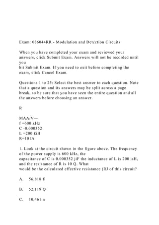
- 1. Exam: 086044RR - Modulation and Detection Circuits When you have completed your exam and reviewed your answers, click Submit Exam. Answers will not be recorded until you hit Submit Exam. If you need to exit before completing the exam, click Cancel Exam. Questions 1 to 25: Select the best answer to each question. Note that a question and its answers may be split across a page break, so be sure that you have seen the entire question and all the answers before choosing an answer. R MAA/V— f =600 kHz C -0.000352 L =200 £iH R=101A 1. Look at the circuit shown in the figure above. The frequency of the power supply is 600 kHz, the capacitance of C is 0.000352 jiF the inductance of L is 200 |aH, and the resistance of R is 10 Q. What would be the calculated effective resistance (RJ of this circuit? A. 56,818 fi B. 52,119 Q C. 10,461 n
- 2. D. 43,167 n 2. An unmodulated carrier has an amplitude of 5 V. When modulated, the maximum amplitude is 10 V. What is the modulation percentage? A. 50 percent B. 120 percent C. 30 percent D. 100 percent 3. In a standard AM transmission with 100 percent modulation, A. the sideband amplitude is 70.7 percent of the carrier amplitude. B. the sideband amplitude is one-eighth of the carrier amplitude. C. the sideband amplitude is one-fourth of the carrier amplitude. D. the sideband amplitude is 50 percent of the carrier amplitude. ^A/Wsr- f =600 kHz C =0,000352 fiF L=20QmH
- 3. R=ioy? 4. For the circuit shown in the figure above, what would be the calculated value of the inductive reactance (Xj)? (Round your answer to the nearest whole number.) A. 942 D. B. 1,057 a C. 754 a D. 598 a 5. A 1.5 MHz carrier frequency is amplitude-modulated by a 200 kHz sinewave audio signal. The bandwidth would be A. 4,000 kHz. B. 400 kHz. C. 405 kHz. D. 40 kHz. 6 . modulation is particularly adaptable to computer systems, data transmission, and space communications. A. Pulse-amplistude B. Pulse-position C. Phase
- 4. D. Pulse 7. Some methods of pulse modulation provide for transmission of a number of channels on a single carrier. That is accomplished by dividing the transmission time among the several channels, which is called A. damping. B. multiplexing. C. frequency-shift keying. D. duplexing. 8. A 1,200 kHz RF carrier is amplitude-modulated by a 500 Hz sinewave audio signal. The upper sideband frequency would be A. 1,195 kHz. B. 1,205 kHz. C. 120.5 kHz. D. 1,200.5 kHz. 9. In a Foster-Seeley phase shift discriminator, certain voltage conditions depend on whether the input signal is at, above, or below resonance. Look at the vector diagram shown in the figure above. Which of the following statements correctly describes the circuit represented by this vector diagram?
- 5. A. The input signal in this circuit is at resonance, and the discriminator's secondary voltages cancel each other. B. The input signal is above resonance, and no output signal will be produced. C. The output signal produced will be directly proportional to the frequency deviation of the input signal. D. The input signal is below resonance, and the output signal produced will be of opposite polarity. 10. In modulation, the position or spacing of an intelligence pulse relative to a reference point is its principle of operation. A. pulse-amplitude B. pulse-code C. pulse-position D. phase 11. An amplitude-modulated RF carrier is said to be percent modulated when it rises to double its peak value on a modulation crest (or peak). A. 50 B. 75 C. 25 D. 100
- 6. 12. Which of the following is used by a product detector? A. A ratio detector B. Amplitude limiting C. An oscillator for carrier reinsertion D. A special transformer M/VW f =600 kHz C =0.000352 pF L=2QQMH r = i o v? 13. For the circuit shown in the figure above, what would be the calculated value of Q for the circuit? A. 127.3 B. 94.2 C. 148.2 D. 75.4 14. In pulse-code modulation, numbers are used to represent the waveform's A. time. B. amplitude.
- 7. C. phase. D. frequency. R M/WV— f =600 kHz C =0,000352/jF L =200 juH R = 10 Vi 15. For the circuit shown in the figure above, what would be the calculated value of the circuit bandwidth? A. 7,958 Hz B. 9,925 Hz C. 3,714 Hz D. 1,047 Hz 16. All receivers that are designed for suppressed carrier reception must be able to A. block any trace of a carrier. B. reinsert a carrier frequency. C. eliminate one sideband. D. reduce modulation phase shift.
- 8. 17. In pulse-modulated systems, the interference caused by the operation of electronic switches is called A. jitters. B. dead air. C. envelope distortion. D. damped waves 18. An advantage of the ratio detector over the discriminator is that the ratio detector A. is cheaper to build. B. doesn't require a limiter. C. requires only two diodes. D. doesn't require an RF amplifier. 19 . modulation is based on the use of a coded series of bits that may be marks or spaces. A. Coded B. Pulse-position C. Pulse-code D. Pulse-amplitude 20. An unmodulated carrier has an amplitude of 10 V. When modulated, the maximum amplitude is 15 V. What's the modulation percentage?
- 9. A. 120 percent B. 50 percent C. 30 percent D. 100 percent 21. A 1,000 kHz RF carrier is amplitude-modulated by a 5,000 Hz sinewave signal. The upper sideband frequency would be A. 1,005 kHz. B. 995 kHz. C. 1,010 kHz. D. 1,005.5 kHz. 22. When a divide-by circuit is added to a PLL, the PLL can be used as a(n) A. AM detector. B. audio amplifier. C. amplitude limiter. D. frequency synthesizer. 23. The term that's used to express the amount of change from the frequency of the unmodulated carrier is
- 10. A. deviation. B. idling change. C. modulation index. D. detection. 24. Which of the following is a type of quanticized pulse modulation? A. Pulse-position modulation B. Pulse-amplitude modulation C. Pulse-quantity modulation D. Pulse-code modulation 25. The amount of modulation of a carrier is usually given as a modulation A. quantity. B. selection. C. percentage. D. maximum. End of exam Exam: 086045RR - Electronic Devices and Amplification
- 11. When you have completed your exam and reviewed your answers, click Submit Exam. Answers will not be recorded until you hit Submit Exam. If you need to exit before completing the exam, click Cancel Exam. Questions 1 to 20: Select the best answer to each question. Note that a question and its answers may be split across a page break, so be sure that you have seen the entire question and all the answers before choosing an answer. 1. A certain amplifier has an input of 3 Y and output of 12 V. The voltage gain is V. A. 12 B. lU C. 4 D. 3 2. If the secondary winding of a transformer has five times as many turns as the primary winding, the secondary voltage will be the primary voltage. A. five times B. one-fifth of C. twenty-five times D. the same as 3. The primary-to-secondary turns ratio of a certain
- 12. transformer is 3:12. The AC voltage across the secondary has been calculated as 30 V. What is the AC voltage across the primary? A. 14.08 V B. 12.43 V C. 7.5 V D. 10.25 V 4. In a typical op amp, what is the relation of the output impedance to the input impedance? A. The output impedance is less than the input impedance. B. The maximum gain is less than one. C. The two signals are in phase with each other. D. One signal is 90 degrees out of phase with the other. RELAY COIL NPN TRANSISTOR ¦o -o -o /
- 13. + = V 5. Look at the circuit illustrated in the figure above. When you use an NPN transistor as a relay driver as shown in the figure, the relay pulls in when the transistor A. emitter goes high. B. base goes low. C. collector goes high. D. collector goes low. 6. A DC amplifier will amplify signals down to a low- frequency limit of 7. A certain transformer has a primary-to-secondary turns ratio of 3 : 8. If the AC voltage across the transformer primaiy is 60 V, what would be the AC voltage across the secondaiy winding? 8. Look at the drawing shown in the figure above. When you see this drawing in a schematic diagram, you should recognize that it represents a/an A. 100 Hz. B. 0 Hz. C. 1,000 Hz. 0. 10 Hz.
- 14. A. 280 V B. 100 V C. 220 V D. 160 V A. step-up transformer. B. inverter. C. thermal relay. D. bridge rectifier. 9. A transformer has a 2 : 3 primary-to-secondary turns ratio. If the number of turns in the primary winding were doubled while the number of turns in the secondary stayed the same, the transformer would become a/an transformer. A. impedance B. step-up C. step-down D. isolation 10. The primary-to-secondary turns ratio of a certain transformer is 2:5. If the AC voltage across the transformer primary is 50 V, what would be the AC voltage across the secondary winding?
- 15. A. 290 V B. 235 V C 180 V D. 125 V 11. A three-stage amplifier produces gains of 15 dB per stage and has equal input and output impedances. The overall gain of the amplifier will be dB. A. 337.5 B. 225 C. 45 D. 30 12. The primary-to-secondary turns ratio of a certain transformer is 3 : 8. If the AC current in the primary is 16 A, what would be the calculated value of the secondary current? A. 2.5 A B. 4.8 A C. 9.2 A D. 6 A 13. A certain relay has a voltage rating of 20 V. The pull-in voltage of the relay should be about
- 16. V. A. 24 B. 3.6 C. 12 D. 7.2 14. The primary-to-secondary turns ratio of a certain transformer is 2 : 9. The AC voltage across the secondary has been calculated as 24 V. What is the AC voltage across the primary? A. 1.26 V B. 10.14 V C. 8.05 V D. 5.33 V 15. Which of the following is a passive component that's used to modify frequency response? A. A double-balanced modulator B. A regulated power supply C. An LC filter D. A radio receiver
- 17. 16. A technician wants to connect several amplifiers across a transmission line without loading down the line. Which of the following amplifiers would be the best choice for this application? A. Servo amplifiers B. Compression amplifiers C. Bridging amplifiers D. Limiter amplifiers 17. A characteristic of a push-pull amplifier is that it harmonics. A. increases the levels of odd B. reduces the levels of odd C. reduces the levels of even D. increases the levels of even 18. A certain transformer has a 6 : 1 turns ratio, and its secondary connects to a 10 Q impedance. What value of impedance is required at the primary of the transformer to provide a proper impedance match? A. 360 £2 B. 420 n C.300 Q D. 275 Q
- 18. 19. The usual results of applying negative feedback in an amplifier are distortion. A. reduced frequency response and less B. reduced frequency response and more C. better frequency response and less D. better frequency response and more 20. If an RF splitter has two output ports, how much theoretical loss is to be expected due to the shunt resistor and leakage? A. 6 dB B. 1 dB C. 9dB D. 3 dB End of exam Exam: 086027RR - Using Basic Oscilloscopes When you have completed your exam and reviewed your answers, click Submit Exam. Answers will not be recorded until you hit Submit Exam. If you need to exit before completing the
- 19. exam, click Cancel Exam. Questions 1 to 25: Select the best answer to each question. Note that a question and its answers may be split across a page break, so be sure that you have seen the entire question and all the answers before choosing an answer. 1. Which of the following scope probe connections should be used to make a measurement from an integrated circuit lead? A. An extender on the probe B. A direct probe connection C. A needle-tip probe D. A point-type probe contact 2. A waveform that's displayed on the screen of an oscilloscope is called a A. line. B. signal. C. trace. D. scan 3. What is the frequency of an AC signal that takes 50 (is to complete one cycle? A. 200 Hz B. 20 kHz
- 20. C. 12 kHz D. 2 kHz 4. You're about to make a measurement with an oscilloscope when you find that the trace appears to be very weak on the screen. Which of the following controls would you adjust to make the trace appear brighter? A. The slope control B. The focus control C. The level control D. The intensity control 5. What is the maximum AC input voltage (peak-to-peak) that most oscilloscopes can safely measure? A. 1,600 V-l ,800 V B. 1,000 V-l,400 V C. 800 V-l,000 V D. 600V-800V 6. One cycle of a sine wave contains five divisions. If the time base is set to one millisecond per division, how long will it take this sine wave to complete one cycle?
- 21. A. 50 milliseconds B. 0.5 millisecond C. 5 milliseconds D. 0.05 millisecond 7. What is the duty cycle of a square wave that's positive for two horizontal divisions and at zero volts for four horizontal divisions? A. 45 percent B. 25 percent C. 33 percent D. 65 percent 8. The amount of phase shift between input and output signals is important when measuring A. TRIAC circuits. B. servo circuits. C. SCR circuits. D. transistor circuits. 9. The horizontal sweep frequency signal that's used to move the electron beams across an oscilloscope screen is a type of A. triangular wave.
- 22. B. square wave. C. sine wave. D. sawtooth wave. 10. An AC voltage that's present on a DC power supply's output is called A. oscillation. B. distortion. C. flicker. D. ripple. 11. A DIP clip is usually used to measure A. integrated circuits. B. relays and solenoids. C. SCR circuits. D. high voltages. 12. To increase the vertical size of a 2 V square waveform that appears only one-half division high on your scope screen, you should adjust the A. volts per division control. B. time base control.
- 23. C. coupling switch to ADD. D. veitical position control. 13. In an amplifier circuit that contains a transistor in a common-emitter configuration, the phase shift between the input signal and the output signal will usually be A. 90 degrees. B. 30 degrees. C. 180 degrees. D. 60 degrees. 14. The deflection plates in a CRT are operated by a varying A. voltage. B. resistance. C. current. D. power. 15. A portable, battery-powered oscilloscope is very lightweight and can operate for many hours before its batteries need to be recharged. Which of the following screens would this oscilloscope contain? A. An LCD screen B. A plasma screen
- 24. C. An LED screen D. A CRT screen 16. If you viewed a digital clock frequency signal on an oscilloscope, what type of waveform would you see on the scope screen? A. A sawtooth wave B. A sine wave C. A triangular wave D. A square wave 17. You wish to measure the AC value of a composite signal made up of both AC and DC voltages. The coupling switch should be set to A. AC. B. DC. C. GND. D. EXT. 18. Your oscilloscope's test probe is placed in the 10X or 10:1 position. You measure a waveform as being 4 VAC peak-to-peak. What is the actual voltage at this test point? A. 40 VAC
- 25. B. 4 VAC C. 0.4 VAC D. 0.04 VAC 19. On an oscilloscope's graticule, the center horizontal line (the x-axis) represents units of A. phase. B. night. C. time. D. voltage. 20. A sine wave signal takes 0.01 second to complete one cycle. What is the frequency of this signal? A. 80 Hz B. 100 Hz C. 120 Hz D. 60 Hz 21. In a CRT, the direction of electron beam deflection depends on the A. polarity of the voltage that's applied to the deflection plates.
- 26. B. type of inert gas that the tube contains. C. amount of voltage that's applied to the deflection plates. D. size of the screen. 22. The major divisions on an oscilloscope's graticule are usually separated by a distance of A. l/4 inch. B. 1 centimeter. C. 1 millimeter. D. '/g inch. 23. A scope's time base is set to 0.05 ms per division. An AC waveform takes five divisions to complete one cycle. What is the frequency of the signal? A. 8 kHz B. 10 kHz C. 4 kHz D. 6 kHz 24. A waveform takes 0.0002 second (0.2 millisecond) to complete one cycle. What is the frequency of this signal? A. 200 hertz B. 5 kilohertz
- 27. C. 2 hertz D. 50 kilohertz 25. The connector that's used to attach a probe to an input terminal of a scope is called a(n) A. T-type connector. B. BNC connector. C. F-type connector. D. Phono style connector. End of exam Exam: 002908RR - Electronics Practical Exercise 8 When you have completed your exam and reviewed your answers, click Submit Exam. Answers will not be recorded until you hit Submit Exam. If you need to exit before completing the exam, click Cancel Exam. Questions 1 to 20: Select the best answer to each question. Note that a question and its answers may be split across a page break, so be sure that you have seen the entire question and all the answers before choosing an answer. SYMBOL A SYMBOL B SYMBOL C SYMBOL D
- 28. r SYMBOL E SYMBOL F SYMBOL G 1. Of the symbols that are represented in the figure, you would need to carefully observe the polarity if you were replacing A. symbol A, symbol C, symbol D, and symbol E. B. symbol A, symbol C, and symbol D. C. symbol A, symbol B, symbol C, symbol E, and symbol G. D. symbol A, symbol C, symbol E, and symbol G. signal. The labeled value is equal to 1.9 times the value of Ec. Which of the following statements about this waveform is correct? A. Increasing the frequency of the modulating signal will increase the number of sidebands. B. Only one sideband is generated because the carrier is undermodulated. C. There's still room to increase the amplitude of the modulating signal without introducing distortion. D. An infinite number of sidebands is generated because of overmodulation. PRIMARY SECONDARY
- 29. 1,920 Q Z- 30 Q 3. Look at the transformer in the figure. Suppose that the impedance in the secondary is reduced to 15 £1 To maintain an impedance match, the primary impedance must be A. reduced to 96012. B. reduced to 240 £2. C. increased to 3,840 Q. D. increased to 7,680 £2. POINT 1 POINT 2 POINT 3 POINT 4 POINT 5 4. In the figure above, suppose that the amplitude of the modulating signal was increased in amplitude. What effect would you expect to see on the modulated carrier wave? A. The resting frequency of the carrier will increase. B. The rate at which the frequency changes will increase. C. The amount of frequency shift of the carrier will increase. D. The amplitude of the modulated carrier will increase. PRIMARY SECONDARY Z= 1,920 0 Z = 30 Q 5. Look at the transformer in the figure. This transformer correctly matches the primary and secondary impedance. Which of the following statements about the turns ratio of this transformer is correct?
- 30. A. There are eight times as many turns in the primaiy as in the secondaiy. B. There are four times as many turns in the primaiy as in the secondary. C. There are eight times as many turns in the secondary as in the primary. D. There are four times as many turns in the secondaiy as in the primary. SIGNAL SOURCE sv/ div 6. When the oscilloscope probe is disconnected from the circuit in the figure, the trace becomes flat and moves up two divisions on the screen. This reaction indicates that A. a positive DC component is riding on the waveform. B. the oscilloscope is defective and can't be trusted. C. a negative DC component is riding on the waveform. D. the waveform contains a modulating signal of a much higher frequency. 7. Look at the circuit in the figure. This circuit is used to demagnetize a television picture tube each time
- 31. the set is turned on. The coil surrounds the tube and is energized with an alternating current that quickly decays to zero over a period of several seconds. Which of the following components would you expect to find connected in series with this coil? A. A step-up transformer B. A PTC thermistor C. A Hall-effect device D. A piezoelectric device COMPONENT COIL PLACED AROUND THE PICTURE TUBE OSCILLATOR 8. When you're working with the circuit shown in the figure above, which of the following oscilloscope controls would you adjust to display more cycles of the waveform on the screen? A. The time/cm control B. The horizontal sync control C. The horizontal positioning control D. The volts/division control
- 32. POINT 1 POINT 2 POINT 3 POINT A POINT 5 9. Look at the waveforms illustrated in the figure above. At what point (or points) will the carrier wave be at its idling frequency? A. At point 2 and point 4 B. At point 1, point 3, and point 5 C. At point 2 only D. At point 4 only OSCILLATOR 10. Look at the schematic diagram in the figure above. The oscillator shown generates a sine wave with a small DC component. The waveform produced by the oscillator is shown on the oscilloscope. The thermistor in the circuit has a positive temperature coefficient. What will happen to the waveform of this circuit if the temperature rises? A. The waveform will drift downward on the oscilloscope screen. B. The amplitude of the waveform will increase. C. The amplitude of the waveform will decrease. D. The waveform will drift upward on the oscilloscope
- 33. screen. SYMBOL A SYMBOL B SYMBOL C SYMBOL D r j SYMBOL E SYMBOL F SYMBOL G 11. Which of the symbols in the figure represent components that are able to generate a voltage? A. Symbol A, symbol C, and symbol G B. Both symbol A and symbol C C. Only symbol A D. Symbol A, symbol C, symbol E, and symbol G 12. Look at the schematic diagram in the figure above. Which of the following actions would result in a change in the meter reading? A. Changing the pressure or the light level B. Changing the light level or the temperature C. Changing the humidity or the temperature D. Changing the magnetic flux or the pressure SYMBOL A SYMBOL B SYMBOL C SYMBOL D n
- 34. y T SYMBOL E SYMBOL F SYMBOL G 13. Light is often used to couple signals between circuits in which noise pickup is a factor. Of the symbols that are represented in the figure, which of the following are likely to be used for this purpose? A. Symbol A, symbol B, symbol C, symbol E, and symbol G B. Symbol A, symbol C, symbol D, symbol E, and symbol G C. Symbol A and symbol B D. Symbol A, symbol C, and symbol E 14. In the figure, suppose that the amplitude of the modulating signal is increased so that the value of EMAX is equal t0 2"2 times the Yalue EC- which of tlie f0ll0wing statements about this waveform would be correct? A. The modulator now operates at a higher level of efficiency than before. B. All of the power in the waveform is now in the sidebands. C. The output power of the transmitter will be reduced. D. Sidebands are now generated that aren't representatives of the modulating signal.
- 35. 15. To center the waveform on the oscilloscope display in the figure above, which of the following controls would you use? A. The vertical sensitivity control B. The time base control C. The sync amplitude control D. The vertical positioning control © SYMBOL A SYMBOL B SYMBOL C SYMBOL D SYMBOL E SYMBOL F SYMBOL G 16. Which of the schematic symbols in the figure represents a varistor? A. None of the symbols shown in the figure represents a varistor. B. Both symbol A and symbol C C. Symbol F D. Symbol G division vertically and 5 microseconds per division horizontally. What's the frequency of this waveform? A. 100 kHz
- 36. B. 1,000 Hz C. 1 kHz D. 10 kHz 18. Look at the circuit in the figure. An oscilloscope is connected to the circuit and the waveform being measured is displayed on the scope screen. With the connections shown, the RMS of the voltage displayed on the screen must be A. 100 V. B. 7.07 V. C. 70.7 V. D. 3.53 V. SYMBOL A SYMBOL B SYMBOL C SYMBOL D n SYMBOL E SYMBOL F SYMBOL G 19. The schematic symbols for several components are illustrated in the figure. Which of the schematic symbols shown in the figure represents a phototransistor? A. Symbol E B. Both symbol C and symbol F C. Symbol B
- 37. D. None of the symbols shown in the figure represents a phototransistor. 20. The oscilloscope screen shown is set to display 5 volts per division vertically and 5 microseconds per division horizontally. What's the peak-to-peak amplitude of the waveform shown in the figure above? A. 5 V B. 10 V C. 70.7 V D. 7.7 V End of exam L i- 1- 1- n