Ndir gas sensing circuit
•Download as PPTX, PDF•
0 likes•170 views

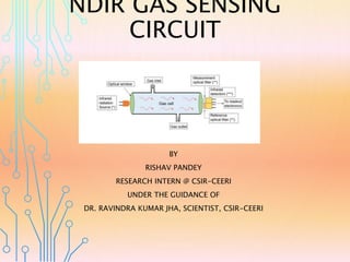
Explanation of the circuit diagram of basic NDIR system.

Recommended
More Related Content
What's hot
What's hot (20)
Similar to Ndir gas sensing circuit
Similar to Ndir gas sensing circuit (20)
More from Rishav Pandey
Recently uploaded
Recently uploaded (20)
Ndir gas sensing circuit
- 1. NDIR GAS SENSING CIRCUIT BY RISHAV PANDEY RESEARCH INTERN @ CSIR-CEERI UNDER THE GUIDANCE OF DR. RAVINDRA KUMAR JHA, SCIENTIST, CSIR-CEERI
- 2. NDIR GAS SENSING CIRCUIT
- 3. CIRCUIT COMPONENTS…. The following components are used to design a circuit diagram of basic NDIR system: 1. Lamp (An IR light source). 2. Active and Reference optical filters. 3. IR Detectors (consisting of Thermopiles and Thermistor) 4. Two AD8629 Operational Amplifiers. 5. One ADA4528-1 low noise amplifier. 6. One ADuCM360 analog microcontroller (consisting of ADCs, Muxes, etc) 7. One ADP7105 low drop regulator.
- 4. CIRCUIT EXPLANATION…. • The printed circuit board (PCB) is designed in an Arduino shield form factor and interfaces to the EVAL- ADICUP360 Arduino-compatible platform board. The signal conditioning is implemented with the AD8629 and the ADA4528-1 low noise amplifiers and the ADuCM360 precision analog microcontroller, which contains programmable gain amplifiers, dual 24-bit Σ-Δ analog-to digital converters (ADCs). • The thermopile sensor is composed of a large number of thermocouples connected usually in series or, less commonly, in parallel. The output voltage of the series connected thermocouples depends on the temperature difference between the thermocouple junctions and the reference junctions.
- 5. CONTINUED…. • The circuit uses the AD8629 op amp to amplify the thermopile sensor output signals. • The ADP7105 low dropout regulator generates a stable 5 V output voltage to drive the lamp, and is turned on and off by the ADuCM360. • In the NDIR application, pulsed and filtered IR light is applied to the series connected active junctions; the junctions are therefore heated, which in turn generates a small thermoelectric voltage. The temperature of the reference junction is measured with a thermistor.
- 6. REFERENCES…. • https://www.co2meter.com/ • https://en.gassensor.com.cn/ • https://www.analog.com/ • https://www.researchgate.net/