1. Raul Martinez, Electrical & Computer Engineering and Computer Science, Syracuse University, Syracuse, NY 13210
Carl Schultheiss, Collider-Accelerator Department: Collider Electric Power Supply Group, Brookhaven National Laboratory, Upton, NY 11973
This project was supported in part by the U.S. Department of Energy, Office of Science, Office of
Workforce Development for Teachers and Scientists (WDTS) under the Science Undergraduate
Laboratory Internships Program (SULI).
I’d personally like to thank the Collider-Accelerator Department, specifically the Collider Electrical
Power Supply Group, especially mentor, Carl Schultheiss, for his extensive support throughout my
project. I’d also like to thank BNL’s Office of Educational Programs, especially Noel Blackburn, Mike
Stegman, Sal Gonzalez, and Cindi Biancarosa for their support throughout my project and time at
Brookhaven National Lab.
ACKNOWLEDGEMENTS
Abstract
One of Brookhaven National Laboratory’s (BNL) highly used research facilities is the Relativistic Heavy
Ion Collider (RHIC). The RHIC’s main magnet power supply controls the current that steers its beams
around it’s rings and at the heart of this power system is the Phase-Locked Loop (PLL) & Silicon Control
Rectifier (SCR) Firing Board. This board uses a PLL to track the frequencies of the incoming power line
that is then used as clock signals to the SCR digital firing section of the board that control which SCR
pairs to fire; the SCR’s power the main magnet. Being active for almost two decades the RHIC’s
hardware has been used extensively and could be experiencing internal issues and without the board
functioning correctly the RHIC will not operate properly. Due to these potential issues a diagnostics
system was deemed necessary to be added to the board in order to provide internal real time data. This
diagnostic system needed to be designed so that it could read and write data from several different PLL,
SCR, and Murray Filter components every time a new set of data was available. That meant that the
diagnostics needed to be fast enough to read all of the data from the desired components and write
them into a memory block.
Designing The Diagnostic System
The overall goal for this diagnostic system was to check that the piece of hardware the system was
being implemented into, which in this case was the PLL and SCR Firing Board, and seeing if it was
operating correctly and properly executing the functions that it was programmed to do. We where
interested in finding out if the PLL itself was working correctly for this specific design, and the PLL
control system is composed of modules that include a low-pass filter, a numerical controlled oscillator, a
phase detector, and a phase accumulator. In order to check its functionality data had to be acquired
from different parts of the system so that is could be analyzed. Since this is a big system there are
multiple data paths that reason was that the multiplexer would allow for multiple inputs but only output
the data that was selected into memory, which is the next piece of the system. All the data that was
being outputted needed to be stored somewhere. Since the system sample rate was going to be the
frequency of the firing card which was around 44.2kHz, the memory needed to be big enough to take
enough samples every second and the samples where going to be 32-bit words. The multiplexer would
handle the data being written to memory and the next piece of the system would help select which
piece of data to be written and when it would be written. In order to do that a finite state machine
needed to be implemented into the system. The finite state machine would handle selecting which
p i e c e o f d a t a t o b e i n p u t t e d . B e l o w i s a b l o c k d i a g r a m o f t h e
system that was described. You can see which data points where important as well as the different
clocks that are running the system.
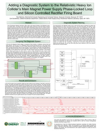
Results and Conclusion
Diagnostic System Planning
In the end, the Diagnostic System design is composed of three modules; a multiplexer, memory bank and
state machine. The first one is a 5:1 Multiplexer where the data was going read into. There where seven
signals that we were interested in but four of them whee16-bit outputs so they where concatenated at the
buss. The data would become valid at a rate of 44.8kHz. The next module is a 32 State Finite State Machine.
This state machine was going to act as the multiplexer’s select as well as the memory's enable and clock
depending on which state was the current state. The state machine would also generate a 19-bit address
t h a t w a s g o i n g t o b e s e n t i n t o t h e m e m o r y s o t h a t t h e
selected output data component could be read and written into a Memory Bank. The memory bank used for
the system was a 44900x32-bit Dual Port RAM that would then output what was written to the VME. Once
the system design plan was established the system was able to be programmed. The system was designed
and implemented using the Very High-Level Design Language-Verilog and the Altera Quartus II
programmable logic device (PLD) design software. The image below shows the final compiled version of the
Diagnostic System after everything was correctly connected; it is the system’s RTL diagram.
Adding a Diagnostic System to the Relativistic Heavy Ion
Collider’s Main Magnet Power Supply Phase-Locked Loop
and Silicon Controlled Rectifier Firing Board
In the end the system was successfully created and when loaded onto the hardware it was able to execute it’s
function. The system was loaded onto a testing card and put to use to check its operation. The system was able
to load the data wanted into the multiplexer and successfully write it onto the memory bank. The state machine
state transition timing was good and the multiplexer hold and set times where properly met so the data didn’t
get lost at the bus, The addresses generated by the state machine where properly incrementing and reset as
soon as the memory bank was filled and ready to be outputted. The image below shows a screenshot of a logic
analyzer that shows the system properly functioning. We can see the state transitions occurring at the rising
edge of the clock, as well as the state outputs which select that data from the multiplexer and enabled the RAM.
We can also see the proper data being loaded into the multiplexer. In the end the system properly worked and
executed its main functions. Now that it is finished it can be loaded onto any card and gather data. The system
application will allow the user to gather data and use it to analyze if the card is properly operating.