College Call Girls Nashik Nehal 7001305949 Independent Escort Service Nashik
UNIT 1 FINAL NOTES.pdf
1. Unit 1 Stepper Motor
EEE Dept-DrNGPIT
Constructional features –Principle of operation –Types – Torque predictions – Linear
Analysis – Characteristics – Drive circuits – Closed loop control – Concept of lead angle -
Applications.
Stepper Motor Basics
A stepper motor is an electric motor whose main feature is that its shaft rotates by
performing steps, that is, by moving by a fixed amount of degrees. This feature is obtained
thanks to the internal structure of the motor, and allows to know the exact angular position
of the shaft by simply counting how may steps have been performed, with no need for a
sensor. This feature also makes it fit for a wide range of applications.
What is a Stepper Motor : Types & Its Working
A stepper motor is an electromechanical device it converts electrical power into
mechanical power. Also, it is a brushless, synchronous electric motor that can divide a full
rotation into an expansive number of steps. The motor’s position can be controlled
accurately without any feedback mechanism, as long as the motor is carefully sized to the
application. Stepper motors are similar to switched reluctance motors. The stepper motor
uses the theory of operation for magnets to make the motor shaft turn a precise distance
when a pulse of electricity is provided. The stator has eight poles, and the rotor has six
poles. The rotor will require 24 pulses of electricity to move the 24 steps to make one
complete revolution. Another way to say this is that the rotor will move precisely 15° for
each pulse of electricity that the motor receives.
Construction & Working Principle: GENERAL
The construction of a stepper motor is fairly related to a DC motor. It includes a
permanent magnet like Rotor which is in the middle & it will turn once force acts on it. This
rotor is enclosed through a no. of the stator which is wound through a magnetic coil all
over it. The stator is arranged near to rotor so that magnetic fields within the stators can
control the movement of the rotor.
The stepper motor can be controlled by energizing every stator one by one. So the stator
will magnetize & works like an electromagnetic pole which uses repulsive energy on the
rotor to move forward. The stator’s alternative magnetizing as well as demagnetizing will
shift the rotor gradually &allows it to turn through great control.
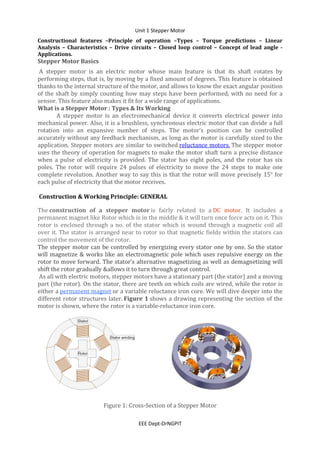
As all with electric motors, stepper motors have a stationary part (the stator) and a moving
part (the rotor). On the stator, there are teeth on which coils are wired, while the rotor is
either a permanent magnet or a variable reluctance iron core. We will dive deeper into the
different rotor structures later. Figure 1 shows a drawing representing the section of the
motor is shown, where the rotor is a variable-reluctance iron core.
Figure 1: Cross-Section of a Stepper Motor
3. Unit 1 Stepper Motor
EEE Dept-DrNGPIT
The Stepper Motors therefore are manufactured with steps per revolution of 12, 24, 72,
144, 180, and 200, resulting in stepping angles of 30, 15, 5, 2.5, 2, and 1.8 degrees per step.
The stepper motor can be controlled with or without feedback. A Stepper Motor or a step
motor is a brushless, synchronous motor which divides a full rotation into a number of
steps. Unlike a brushless DC motor which rotates continuously when a fixed DC voltage is
applied to it, a step motor rotates in discrete step angles.
Stepper motors work on the principle of electromagnetism. There is a soft iron or magnetic
rotor shaft surrounded by the electromagnetic stators. The rotor and stator have poles
which may be teethed or not depending upon the type of stepper. When the stators are
energized the rotor moves to align itself along with the stator (in case of a permanent
magnet type stepper) or moves to have a minimum gap with the stator (in case of a
variable reluctance stepper). This way the stators are energized in a sequence to rotate the
stepper motor.
The basic working principle of the stepper motor is the following: By energizing one or
more of the stator phases, a magnetic field is generated by the current flowing in the coil
and the rotor aligns with this field. By supplying different phases in sequence, the rotor can
be rotated by a specific amount to reach the desired final position. Once the stators of this
motor are energized then the rotor will rotate to line up itself with the stator otherwise
turns to have the least gap through the stator. In this way, the stators are activated in a
series to revolve the stepper motor.
Figure 2 shows a representation of the working principle. At the beginning, coil A is
energized and the rotor is aligned with the magnetic field it produces. When coil B is
energized, the rotor rotates clockwise by 60° to align with the new magnetic field. The
same happens when coil C is energized. In the pictures, the colors of the stator teeth
indicate the direction of the magnetic field generated by the stator winding.
Figure 2: Stepper Motor Steps
Step Angle
It is defined as the angular displacement of the rotor in response to each pulse.
Step angle = Difference of the rotor pitch and the stator pitch
Where, Stator pitch = 360/Number of stator poles
Rotor pitch = 360/Number of rotor poles
Smaller the step angle, greater the number of steps per revolution and higher
the resolution or accuracy of positioning obtained. The step angles can be as small as
0.72o or as large as 90o. But the most common step sizes are 1.8o, 2.5o, 7.5o and 15o.
Stepper Motor Types and Construction
4. Unit 1 Stepper Motor
EEE Dept-DrNGPIT
The performance of a stepper motor — both in terms of resolution (or step size), speed,
and torque — is influenced by construction details, which at the same time may also affect
how the motor can be controlled. As a matter of fact, not all stepper motors have the same
internal structure (or construction), as there are different rotor and stator configurations.
Rotor
For a stepper motor, there are basically three types of rotors:
Variable reluctance rotor: The rotor is made of an iron core, and has a specific shape that
allows it to align with the magnetic field (see Figure 1 and Figure 2). With this solution it
is easier to reach a higher speed and resolution, but the torque it develops is often lower
and it has no detent torque.
SINGLE STACK VARIABLE RELUCTANCE STEPPER MOTOR
The variable reluctance stepper has a toothed non-magnetic soft iron rotor. When the
stator coil is energized the rotor moves to have a minimum gap between the stator and its
teeth.
Fig. 3: Basic Diagram of Two-Phase Variable Reluctance Stepper Motor
The Stator is made up of silicon steel stampings with inward projected even or odd number
of poles or teeth. Each and every stator poles carries a field coil an exciting coil. In case of
even number of poles the exciting coils of opposite poles are connected in series. The two
coils are connected such that their MMF gets added .the combination of two coils is known
as phase winding.
The rotor is also made up of silicon steel stampings with outward projected poles and it
does not have any electrical windings. The number of rotor poles should be different from
that of stators in order to have self-starting capability and bi direction. The width of rotor
teeth should be same as stator teeth. Solid silicon steel rotors are extensively employed.
5. Unit 1 Stepper Motor
EEE Dept-DrNGPIT
Both the stator and rotor materials must have lowering a high magnetic flux to pass
through them even if a low magneto motive force is applied.
The teeth of the rotor are designed so that when they are aligned with one stator they get
misaligned with the next stator. Now when the next stator is energized, the rotor moves to
align its teeth with the next stator. This way energizing stators in a fixed sequence
completes the rotation of the step motor.
Fig. 4: Diagram Explaining Working of Variable Reluctance Stepper
The resolution of a variable reluctance stepper can be increased by increasing the number
of teeth in the rotor and by increasing the number of phases.
Fig. 5: Figure Showing Ways To Increase Resolution Of Variable Reluctance Stepper Motor
Its rotor is made out of slotted steel laminations and has no winding in it. The stator usually
is wound for three phases. The stator windings are excited with the help of an external
circuit in a specified sequence and the rotor seeks that position in which the reluctance
between the stator and the rotor is minimum. Figure shows a schematic representation of a
variable reluctance stepper motor having six salient poles (teeth) with exciting winding
around each of them. The rotor has four salient projections only. A circuit arrangement for
supplying current to the stator coils in proper sequence is shown in Figure.
Now in this motor, Stator pitch = 360/6 = 60o, Rotor pitch = 360/4 = 90o,
Therefore, Step angle, β = 90 – 60 = 30o
The step angle of this motor is 30o. It means it will move 30o on every application of stator
pulse and will take 360/30 = 12 steps to make a complete revolution.
6. Unit 1 Stepper Motor
EEE Dept-DrNGPIT
Modes of operation -1-phase ON or Full-step Operation
In this mode of operation, one stator phase is excited at one time.
When coil A – A’ is energized by closing switch S1, the rotor is subjected to an
electromagnetic torque and rotates until its axis coincides with the axis of MMF set up by
phase A and takes the position indicated in Figure (a).
Figure 6 (1) Full step operation
7. Unit 1 Stepper Motor
EEE Dept-DrNGPIT
Electrical Connection
Electrical connection of VR stepper as shown fig 6(1). Coil A and A‘ are connected in series
to form a phase winding. This phase winding is connected to a DC source with the help of
semiconductor switch S1.Similary B and B‘ and C and C‘ are connected to the same source
through semiconductor switches S2 and S3 respectively
When coil B – B’ is energized by closing switch S2 and opening S1, the rotor moves through
a full-step of 30o (step-angle) in the clockwise direction and takes the position indicated in
Figure(b).
Similarly, when coil C – C’ is energized by closing switch S3 and opening S2, the rotor moves
through a further step of 30o in the clockwise direction and takes the position indicated in
Figure(c).
Next, when coil A – A’ is energized again by closing switch S1 and opening S3, the rotor
rotates through a further step of 30o in clockwise direction and takes the position indicated
inFigure(d).
By now the total angle turned is 90o. As each switch is closed and the preceding one
opened, the rotor each time moves through a step of 30o.
By successively closing the switches in the sequence 1-2-3-1 and thus exciting stator
phases in sequence ABCA etc. the rotor will rotate clockwise in 30o steps.
If the switching sequence is reversed i.e. 3-2-1-3, the rotor will rotate in the anticlockwise
direction in 30o steps.
This is one type of stepping sequence. In this method, one phase is one at a time. That is,
when phase A is excited, all other phases are OFF. Similarly before exciting the next phase,
the first is turned OFF. The windings are excited one by one for a finite duration like a
wave, hence the name. Here is the stepping sequence diagram.
8. Unit 1 Stepper Motor
EEE Dept-DrNGPIT
Figure 6 (2) Full step operation
2-Phase-ON Mode
The full step sequence or the 2 phase ON sequence, is when two adjacent phase windings
are excited at a time so that the rotor is positioned at a point resultant to both the fields.
Here is the stepping sequence diagram.
Figure 7 Full step operation
In this mode, two stator phases are energized at a time.
When the two phases are excited simultaneously, the rotor is subjected to an
electromagnetic torque from both phases and comes to rest at a point midway between the
two adjacent full-step positions.
If the stator phases are energized in the sequence of AB, BC, CA etc. , the motor will move
in full steps of 30o (as in the 1-phase mode) but its rest positions will be at the
midpoint of the full-step positions.
9. Unit 1 Stepper Motor
EEE Dept-DrNGPIT
Half–step Operation
If we energize the stator in the sequence A, AB, B, BC, C etc. i.e. alternately in the 1-phase-
ON and 2-phase-ON modes the rotor will move in half step angles (30/2 = 15o in this case)
each
time.
10. Unit 1 Stepper Motor
EEE Dept-DrNGPIT
Figure 8(1) Half step operation
11. Unit 1 Stepper Motor
EEE Dept-DrNGPIT
Figure 8(2) Half step operation
Micro Stepping
Here the excitation current is varied gradually. When the rated current is applied to the
phase A and phase B is not excited, the rotor is at vertical position (step 1 of the above
diagram).
Now gradually the current to phase A is reduced and the current to phase B is gradually
increased. Hence the rotor will move by a small angle due to the resultant magnetic field
intensity of phase A and phase B.
When the current in phase A is further decreased and the current to the phase B is
increased the the rotor keeps moving clockwise in very small stepping angels. When the
magnitude of currents in both the phase A and phase B is equal then the magnetic field
intensity is equal and hence the rotor will be positioned in between the two phases (Step 2
of the above diagram).
Stepping motor is a digital actuator which moves in steps of θs in response to input pulses.
such incremental motion results in the following limitations of the stepper motor
Limited resolution
As θs is the smallest angle through which the stepper motor can move, this has an effect on
position accuracy of incremental servo system employing stepper motors because the
stepper motor cannot position the load to an accuracy finer than θs.
Mid frequency Resonance
A phenomenon in which the motor torque suddenly drops to a low value at certain pulse
frequencies as in fig 9(1).
A new principal known as micro stepping control has been developed with a view of
overcoming the above limitation .It enables the stepping motor to move through a tiny
micro step of size ∆ θs << θs full step angle is response to input pulses.
12. Unit 1 Stepper Motor
EEE Dept-DrNGPIT
Fig 9 (1) Mid frequency Resonance
In General view
The rotor takes a position as per excitation of winding:
In position (a) only winding A is energized.
In position (b) both the windings, A and B are energized.
In position (c), winding B is energized and so on.
Figure 9(2) stepper motor operation
MULTI STACK VARIABLE RELUCTANCE STEPPER MOTOR
A Multi Stack or m stack variable reluctance stepper motor is made up of m identical single
stack variable reluctance motor. The rotor is mounted on the single shaft. The stator and
rotor of the Multi Stack Variable motor have the same number of poles and hence, the
same pole pitch.
All the stator poles are aligned in a Multi-Stack motor. But the rotor poles are displaced by
1/m of the pole pitch angle from each other. The stator windings of each stack forms one
phase as the stator pole windings are excited simultaneously. Thus, the number of phases
and the number of stacks are same.
Consider the cross-sectional view of the three stack motor parallel to the shaft is shown
below.
13. Unit 1 Stepper Motor
EEE Dept-DrNGPIT
There are 12 stator and rotor poles in each stack. The pole pitch for the 12 pole rotor is 30,
and the step angle or the rotor pole teeth are displaced by 10 degrees from each other. The
calculation is shown below.
Let Nr be the number of rotor teeth and m be the number of stacks or phases.
Hence, Tooth pitch is represented by the equation shown
below.
As there are 12 poles in the stator and rotor, thus the value of Nr = 12. Now, putting the
value of Nr in the equation (1) we get
14. Unit 1 Stepper Motor
EEE Dept-DrNGPIT
The value of m= 3. Therefore, the step angle will be calculated by putting the value of m in
the equation (2).
When the phase winding A is excited the rotor teeth of stack A are aligned with the stator
teeth as shown in the figure below.
When phase A is de-energized, and phase B is excited, rotor teeth of the stack B are aligned
with the st ator teeth. The rotor movement is about 10 degrees in the anticlockwise
direction. The motor moves one step which is equal to ½ of the pole pitch due to change of
excitation from stack A to stack B. The figure below shows the position of the stator and
rotor teeth when the phase B is excited.
.
Similarly, now phase B is de-energized, and phase C is excited. The rotor moves another
step of 1/3 of the pole pitch in the anticlockwise direction. Again, another change in the
excitation of the rotor takes place, and the stator and rotor teeth align it with stack A.
However, during this whole process (A – B – C – A ) the rotor has moved one rotor tooth
pitch.
Multi Stack Variable Reluctance Stepper Motors are widely used to obtain smaller step
angles in the range of 2 to 15 degrees. Both the Variable reluctance motor Single Stack and
Multi Stack types have a high torque to inertia ratio.
Permanent magnet stepper motor: The rotor is a permanent magnet that aligns with the
magnetic field generated by the stator circuit. This solution guarantees a good torque and
also a detent torque. This means the motor will resist, even if not very strongly, to a change
of position regardless of whether a coil is energized. The drawbacks of this solution are
15. Unit 1 Stepper Motor
EEE Dept-DrNGPIT
that it has a lower speed and a lower resolution compared to the other types. Figure
10 shows a representation of a section of a permanent magnet stepper motor.
Figure 10: Permanent Magnet Stepper Motor
The rotor and stator poles of a permanent magnet stepper are not teethed. Instead the
rotor have alternative north and south poles parallel to the axis of the rotor shaft.
The rotor poles align with the stator teeth depending on the excitation of the winding. The
two coils AA’ connected in series to form a winding of Phase A. Similarly the two coil BB’ is
connected in series forming a phase B windings. The figure below shows 4/2 Pole
Permanent Magnet Stepper Motor.
16. Unit 1 Stepper Motor
EEE Dept-DrNGPIT
Fig. 11: Crossectional Diagram of Permanent Stepper Motor
In figure (a) the current flows start to the end of phase A. The phase winding is denoted by
A+ and the current by i+A. The figure shows the condition when the phase winding is excited
with the current i+A. The south pole of the rotor is attracted by the stator phase A. Thus, the
magnetic axis of the stator and rotor coincide and α = 0⁰
Similarly, in the figure (b) the current flows from the start to the end at phase B. The
current is denoted by i+B and the winding by B+. Considering the figure (b), the windings of
phase A does not carry any current and the phase B is excited by the i+B current. The stator
pole attracts the rotor pole and the rotor moves by 90⁰ in the clockwise direction. Here α =
90⁰
The figure (c) below shows that the current flows from the end to the start of the phase A.
This current is denoted by i–A and the winding is denoted by A–. The current i–A is opposite
to the current i+
A. Here, phase B winding is de-energized and phase A winding is excited by
the current i–A. The rotor moves further 90⁰ in clockwise direction and the α = 180⁰
Fig. 11: Crossectional Diagram of Permanent Stepper Motor
In the above figure (d), the current flows from end to starting point of phase B. The current
is represented by i–B and the winding by B–. Phase A carries no current and the phase B is
excited. The rotor again moves further 90⁰ and the value of α = 270⁰
Completing the one revolution of the rotor for making α = 360⁰ the rotor moves further 90
degrees by de-energizing the winding of phase B and exciting the phase A. In the
permanent magnet stepper motor the direction of the rotation depends on the polarity of
the phase current.The sequence A+, B+, A–, B–, A+ is followed by the clockwise movement of
the rotor and for the anticlockwise movement, the sequence becomes A+ B–, A–, B+, A+.
17. Unit 1 Stepper Motor
EEE Dept-DrNGPIT
The permanent magnet rotor with large number of poles is difficult to make, therefore,
stepper motors of this type are restricted to large step size in the range of 30 to 90⁰. They
have higher inertia and therefore, lower acceleration than variable stepper motors. The
Permanent Magnet stepper motor produces more torque than the Variable Reluctance
Stepper Motor.
When a stator is energized, it develops electromagnetic poles. The magnetic rotor aligns
along the magnetic field of the stator. The other stator is then energized in the sequence so
that the rotor moves and aligns itself to the new magnetic field. This way energizing the
stators in a fixed sequence rotates the stepper motor by fixed angles.
Fig. 12: Diagram Explaining Working Of Permanent Magnet Stepper Motor
The resolution of a permanent magnet stepper can be increased by increasing number of
poles in the rotor or increasing the number of phases.
Fig. 13 Figure Showing Ways to Increase Resolution Of Permanent Magnet Stepper Motor
The rotor made out of permanent magnet material is either of a salient pole or cylindrical
type. The stator has a two or three or four phase winding located in a slotted structure. The
number of slots per pole per phase is usually chosen as one in multipolar machines.
Permanent magnet stepper motors have found the widest application because they have
18. Unit 1 Stepper Motor
EEE Dept-DrNGPIT
good dynamic and static characteristics and a relatively high efficiency.
Figure shows a schematic representation of a 2-pole, 2-phase permanent magnet stepper
motor. In this case,
Rotor pitch = 360/2 = 180o
Stator pitch = 360/4 = 90o
Therefore, step angle β = 180 – 90 = 90o
Since in this case, step angle is 90o, therefore this motor is capable of making discrete steps
of 90o as soon as voltage pulses are applied to the two phases of the exciting winding in a
specified sequence.
The axis of the magnetic field can have four different positions corresponding to two
different directions of flow of current in phases A and B of the exciting winding.
As a result of interaction between the magnetic fields caused by the exciting winding and
the permanent magnet, electromagnetic torque is produced in such a way as to make the
rotor follow the axis of the stator magnetic field.
Hence, the application of each voltage pulse to the exciting winding makes the axis of the
stator field shift by 90o at every switching, thus causing the rotor to make discrete angular
displacements of 90o.
If the direction of current flow in any one of the phases of the exciting winding is reversed,
keeping the sequence of switching same, the direction of rotor movement would be
reversed.
Modes of Operation - 1-Phase ON Mode
In this mode of operation, only one phase is energized at a time.
Consider the figure shown above, here, phase A is energized with positive current ia+. Here,
θ = 0o, rotor moves to the position shown in Figure (a).
Figure 14 (1) . 1-phase mode Permanent Magnet Stepper Motor
Thereafter, phase B is energized with positive current ib+, the rotor moves a full step of
90o in the clockwise direction. Next, phase A is energized again but with negative current
19. Unit 1 Stepper Motor
EEE Dept-DrNGPIT
ia–, the rotor takes another a full step of 90o in the clockwise
direction.
Figure 14 (2) . 1-phase mode Permanent Magnet Stepper Motor
Similarly, phase B is energized again but with negative current ib–, the rotor takes another a
full step of 90o in the clockwise direction. After this, phase A is energized with positive
current ia+, the rotor rotates further a full step of 90o in the clockwise direction.
In this way, the rotor completes one revolution of 360o.
2-Phase ON Mode
In this mode of operation, both the phases are energized simultaneously. In this mode,
resulting steps are of the same size (i.e. 90o) but the rotor pole rests between the two
adjacent full-step positions.
20. Unit 1 Stepper Motor
EEE Dept-DrNGPIT
Half Step Operation
In this mode, 1-phase ON and 2-phase ON modes are used alternatively. The step size
becomes half of the full step (45o in this case) thereby increasing the resolution.
The advantages of a permanent magnet stepper motor are
It is compact and small in size, which makes it useful in many applications
Due to the absence of any external excitation, the losses are less
Due to the absence of any external excitation, the maintenance is less.
It can be connected to the external circuit, to control the speed of the motor
Sensors may be used to locate the rotor windings
Can be operated in a wide range of speed and torque.
Precise Control
The disadvantages of a permanent magnet stepper motor are
Due to limitations in permanent magnet, it cannot be used for high power
applications
Torque produced is limited
The life of a permanent magnet is limited.
Applications
The applications of a permanent magnet stepper motor are
Aeronautical industry
Robotics
Toys
Manufacturing
21. Unit 1 Stepper Motor
EEE Dept-DrNGPIT
Control industry
Mills and printing
Hence we have seen the working principle, constructional aspects, and applications of
the permanent magnet stepper motor.
Hybrid rotor: This kind of rotor has a specific construction, and is a hybrid between
permanent magnet and variable reluctance versions. The rotor has two caps with
alternating teeth, and is magnetized axially. This configuration allows the motor to have the
advantages of both the permanent magnet and variable reluctance versions, specifically
high resolution, speed, and torque. This higher performance requires a more complex
construction, and therefore a higher cost. Figure 15 shows a simplified example of the
structure of this motor. When coil A is energized, a tooth of the N-magnetized cap aligns
with the S-magnetized tooth of the stator. At the same time, due to the rotor structure, the
S-magnetized tooth aligns with the N-magnetized tooth of the stator. Real motors have a
more complex structure, with a higher number of teeth than the one shown in the picture,
though the working principle of the stepper motor is the same. The high number of teeth
allows the motor to achieve a small step size, down to 0.9°.
Figure 15: Hybrid Stepper Motor
Stator
The stator is the part of the motor responsible for creating the magnetic field with which
the rotor is going to align. The main characteristics of the stator circuit include its number
of phases and pole pairs, as well as the wire configuration. The number of phases is the
number of independent coils, while the number of pole pairs indicates how main pairs of
teeth are occupied by each phase. Two-phase stepper motors are the most commonly used,
while three-phase and five-phase motors are less common (see Figure 16 a, b).
22. Unit 1 Stepper Motor
EEE Dept-DrNGPIT
Figure 16 (a): Two-Phase Stator Winding (Left), Three-Phase Stator Winding (Right)
Figure 16 (b): Two-Phase, Single-Pole Pair Stator (Left) and Two-Phase, Dipole Pair Stator
(Right). The Letters Show the Magnetic Field Generated when Positive Voltage is Applied
between A+ and A-.
A hybrid stepper is a combination of both permanent magnet and the variable reluctance. It
has a magnetic teethed rotor which better guides magnetic flux to preferred location in the
air gap.
The construction of stator is similar to variable reluctance otherwise permanent magnet
stepper motor. In this motor, the rotor includes two equal stacks of flexible iron that is
connected to the two poles of an axially magnetized round permanent magnet.
The teeth of the rotor are connected over the poles of soft iron and this is placed on the
shaft. Therefore, these teeth become like a north pole and the South Pole based on the ends,
and these teeth are moved through some angle for the correct position of the rotor pole
using the stator.
23. Unit 1 Stepper Motor
EEE Dept-DrNGPIT
Fig. 17: Construction Of Two phase Hybrid Motor
The magnetic rotor has two cups. One for north poles and second for the south poles. The
rotor cups are designed so that that the north and south poles arrange in alternative
manner.
Fig. 18: Diagram Showing Internal Structure Of Magnetic Rotor In Hybrid Motor
24. Unit 1 Stepper Motor
EEE Dept-DrNGPIT
The Hybrid motor rotates on same principle of energizing the stator coils in a sequence.
Fig. 19: Diagram Explaining Working of Hybrid Stepper Motor
Full step
Half step
25. Unit 1 Stepper Motor
EEE Dept-DrNGPIT
Difference between Permanent Magnet, Variable Reluctance & Hybrid Stepper Motor
The difference between these three motors is discussed below in the tabular format.
Permanent Magnet Variable Reluctance Hybrid Stepper Motor
Step angle is larger or 7.5° Smaller or 1.8° Smaller or 1.8°
Design is Simple Moderate Complex
Response or Acceleration is
Slow Fast Fast
Detent Torque is yes No No
Output torque is moderate Low High
Noise is Quiet Loud Quiet
Speed or Pulse Rate is Low High High
Microstep is Yes No Yes
Hybrid Stepper Motor Advantages
The advantages of Hybrid Stepper Motor are as follows:-
The torque of this motor is high
It gives detent torque including de-energized windings
The step length is less
The efficiency of this motor is high at less speed.
The stepping rate is low.
Hybrid Stepper Motor Disadvantages
The disadvantages of the Hybrid Stepper Motor are as follows
These motors have high inertia
This motor weight is high due to the rotor magnet within the motor
The motor performance will be affected due to magnetic strength.
This motor is expensive
Applications
The Hybrid Stepper Motor applications are as follows
These motors are applicable in the production of automated devices, gauges &
machines used as cutting, labeling, packaging, filling, etc.
These are used in lane diverters, elevators, and conveyor belts.
These are used in security devices like CC cameras
26. Unit 1 Stepper Motor
EEE Dept-DrNGPIT
These are applicable for consumer electronics like printing machines, scanners,
digital cameras, etc.
These motors are used in the medical field for photography of digital dental, liquid
pumps, respirators, the machinery of blood analysis machinery, etc
Thus, this article discusses an overview of the hybrid stepper motor. It is very popular
because it provides good performance in terms of holding torque, speed, and step
resolution as compared with the permanent magnet rotor. But these are more expensive
when contrasted with PM stepper motors.
TERMINOLOGIES USED IN STEPPER MOTOR
1. Step angle
2. Resolution
3. Stepping rate
4. Hold position
5. Detent position
6. Stepping error
7. Position Error
1. Step angle (θs or β)
It is the angular displacement of rotor of a stepper motor for every pulse of excitation
given to the stator winding of the motor. it is determined by the number of teeth on the
rotor and stator, as well as the number of steps in the energisation sequence. It is given by
Where
m = Number of phases (m and q)
Nr- number of teeth on rotor.
Also, Θs=((Ns~Nr)/(Ns.Nr))*360
2. Resolution
It is the number of steps per revolution. It is denoted as S or Z. it is given by
Z=360/(Θs)
For variable reluctance motor Z=(q Nr) or (m Nr)
For PM motor and hybrid motor Z=2q Nr
Also , Z=(Ns.Nr)/(Ns~Nr)
Where Ns-number of teeth/poles on stator.
27. Unit 1 Stepper Motor
EEE Dept-DrNGPIT
3. Stepping Rate
The number of steps per second is known as stepping rate or stepping frequency.
4. Hold Position
It corresponds to the rest position when the stepper motor is excited or energized (this
corresponds to align position of VR motor)
5. Detent Position
It corresponds to rest position of the motor when it is not excited.
6. Stepping Error
Actual step angle is slightly different from the theoretical step angle. This is mainly due to
tolerances in the manufacture of stepper motor and the properties of the magnetic and
other materials used.
The error in the step angle is expressed as a percentage of the theoretical step angle.
%error= ((step angle – theoretical step angle)/theoretical step angle)*100
Percentage error is restricted to ± 5%.In some cases it is restricted to ±2%. The cumulative
error between the actual angular displacement and theoretical angular displacement is
expressed as a percentage of theoretical angular displacement. It is usually considered for
one complete cycle.
7. Positional Error
The maximum range of cumulative percentage of error taken over a complete rotation of
stepper motor is referred to as positional accuracy as shown in fig below.
28. Unit 1 Stepper Motor
EEE Dept-DrNGPIT
THEORY OF TORQUE PREDICTION
According to Faradays laws of electromagnetic induction
If the reluctance of magnetic circuit can be varied, inductance L and the flux linkages λ can
also be varied.
Consider a magnetic circuit as shown in fig. 2.29.
29. Unit 1 Stepper Motor
EEE Dept-DrNGPIT
The stator consists magnetic core with two pole arrangement. Stator core carries a coil.
Rotor is also made up of ferrous material. The motor core is similar to a salient pole
machine. Let the angle between the axis of stator pole and rotor pole be θ. let the angular
displacement be illustrated using fig. 2.29 (a, b and c).
Case 1: θ = 0
As shown in fig. 2.29 (a) the air gap between the stator and rotor is very very small.
Thereby the reluctance of the magnetic path is least. Due to minimum reluctance, the
inductance of the circuit is minimum. Let it be Lmax
Case 2 : θ = 450
As shown in fig. 2.29(b) in this only a portion of rotor poles cover the stator poles.
Therefore reluctance of the magnetic path is more than that of case 1.due to which the
inductance becomes less than Lmax .
Case 3: θ = 900
As shown in fig. 2.29(c) the air gap between the stator poles has maximum value. Thereby
reluctance has a value yielding minimum inductance. Let it be Lmax.
Variation in inductance with respect to the angle between the stator and rotor poles is
shown in fig. 2.30.
Derivation for reluctance torque
As per faradays law of electromagnetic induction an emf induced in an electric circuit
when there exists a change in flux linkages.
30. Unit 1 Stepper Motor
EEE Dept-DrNGPIT
Emf induced e is equal to rate of change of flux linkages / time
If the direction of current I is opposite to that of e, then the electric power is
transferred from the source to the inductor. On the other hand, if the direction of current I
is same as that of e, then the source gets the electrical power from the inductor.
On the basis of magnetic circuit/field theory it is known that the stored energy in a
magnetic field.
The rate of change of energy transfer due to variation in stored energy or power due to
variation in stored energy.
Mechanical power developed/consumed = power received from the electrical
source – power due to change in stored energy in the inductor
Power received from the electrical source = ei
35. Unit 1 Stepper Motor
EEE Dept-DrNGPIT
MICRO STEPPING CONTROL OF STEPPING MOTOR
Figure 8(2) Half step operation
Micro Stepping
Here the excitation current is varied gradually. When the rated current is applied to the
phase A and phase B is not excited, the rotor is at vertical position (step 1 of the above
diagram).
Now gradually the current to phase A is reduced and the current to phase B is gradually
increased. Hence the rotor will move by a small angle due to the resultant magnetic field
intensity of phase A and phase B.
When the current in phase A is further decreased and the current to the phase B is
increased the rotor keeps moving clockwise in very small stepping angels. When the
magnitude of currents in both the phase A and phase B is equal then the magnetic field
intensity is equal and hence the rotor will be positioned in between the two phases (Step 2
of the above diagram).
Stepping motor is a digital actuator which moves in steps of θs in response to input pulses.
such incremental motion results in the following limitations of the stepper motor
Limited resolution
As θs is the smallest angle through which the stepper motor can move, this has an effect on
position accuracy of incremental servo system employing stepper motors because the
stepper motor cannot position the load to an accuracy finer than θs.
Mid frequency Resonance
A phenomenon in which the motor torque suddenly drops to a low value at certain pulse
frequencies as in fig. new principal known as micro stepping control has been
developed with a view of overcoming the above limitation .It enables the stepping motor
to move through a tiny micro step of size ∆ θs << θs full step angle is response to input
pulses.
36. Unit 1 Stepper Motor
EEE Dept-DrNGPIT
Mid frequency Resonance
Principle of micro stepping
Assume a two phase stepper motor operating in ‗one phase ON‘ sequence. Assume also
that only B2 winding is On and carrying current IB2 = IR, the rated phase current. All the
other winding are OFF. In this state the stator magnetic field is along the positive real axis
as show in fig (a). Naturally the rotor will also as be in θ = 0° position.
When the next input pulse comes, B2 is switched OFF while A1 is switched ON.In this
condition IA1= IR while all the phase current are zero. As a result the stator magnetic field
rotates through 90 in counter clockwise direction as show in fig (a).
The rotor follows suit by rotating through 90° in the process of aligning itself with stator
magnetic field. Thus with a conventional controller the stator magnetic field rotates
through 90° when a new input pulse is received causing the rotor to rotate full step.
However in micro stepping we want the stator magnetic field to rote through a small angle
θs << 90° in respect to input pulse. This is achieved by modulating the current through
B2 and A1 winding as show in fig (b) such that
IA1= IR sin θ
IB1= IR cos θ
Then the resulting stator magnetic field will be at an angle θ ° with respect to the positive
real axis. consequently the rotor will rotate through an angle θs << 90° .
This method of modulating current through stator winding so as to obtain rotation of
stator magnetic field through a small angle θ °
Microstepping can be seen as a further enhancement of half-step mode, because it allows to
reduce even further the step size and to have a constant torque output. This is achieved by
controlling the intensity of the current flowing in each phase. Using this mode requires a
more complex motor driver compared to the previous solutions. Figure 14 shows how
microstepping works. If IMAX is the maximum current that can flow in a phase, starting from
37. Unit 1 Stepper Motor
EEE Dept-DrNGPIT
the left, in the first figure IA = IMAX and IB = 0. In the next step, the currents are controlled to
achieve IA = 0.92 x IMAX and IB = 0.38 x IMAX, which generates a magnetic field that is rotated
by 22.5° clockwise compared to the previous one. This step is repeated with different
current values to reach the 45°, 67.5°, and 90° positions. This provides the ability to reduce
by half the size of the step, compared to the half-step mode; but it is possible to go even
further. Using microstepping helps reaching very high position resolution, but this
advantage comes at the cost of a more complex device to control the motor, and a smaller
torque generated with each step. Indeed, the torque is proportional to the sine of the angle
between the stator magnetic field and the rotor magnetic field; therefore, when the steps
are smaller, the torque is smaller. This may lead to missing some steps, meaning the rotor
position does not change even if the current in the stator winding has.
Microstepping
CHARACTERISTICS OF STEPPER MOTOR
Stepper motor characteristics are divided into two groups
Static characteristics and Dynamic characteristics
1. Static characteristics
It is divided into two charteristics.
(i)Torque Angle curve or Torque displacement characteristics
(ii) Torque current characteristics or Torque displacement characteristics
(i)Torque-Angle curve
Torque angle curve of a step motor is shown in below fig. it is seen that the Torque
increases almost sinusoid ally, with angle Θ from equilibrium.
38. Unit 1 Stepper Motor
EEE Dept-DrNGPIT
Holding Torque (TH)
It is the maximum load torque which the energized stepper motor can withstand without
slipping from equilibrium position. If the holding torque is exceeded, the motor suddenly
slips from the present equilibrium position and goes to the static equilibrium position.
It is the maximum load torques which the energized stepper motor can withstand without
slipping from the equilibrium position.
If the holding torque is exceeded the motor suddenly slips from the present equilibrium
position and goes to the next static equilibrium position.
It is the maximum load torque upto which the energized stepper motor can withstand
without slipping.
It is due to residual magnetism and it is 5-10% of holding torque. It is a fourth harmonic
torque also known as caging torque.
Detent torque (TD):
It is the maximum load torque which the un-energized stepper motor can withstand
slipping. Detent torque is due to magnetism, and is therefore available only in permanent
magnet and hybrid stepper motor. It is about 5-10 % of holding torque.
Torque current curve
A typical torque curve for a stepper motor is shown in fig. It is seen the curve is initially
linear but later on its slope progressively decreases as the magnetic circuit of the motor
saturates.
Torque constant (Kt)
Torque constant of the stepper is defined as the initial slope of the torque-current (T-I)
curve of the stepper motor. It is also known as torque sensitivity. Its units N-mA, kg-cm/A
2. Dynamic characteristics
A stepper motor is said to be operated in synchronism when there exist strictly one to one
correspondence between number of pulses applied and the number of steps through which
the motor has actually moved. There are two modes of operation.
39. Unit 1 Stepper Motor
EEE Dept-DrNGPIT
It gives the information regarding the torque stepping rate.The characteristics relating to
motors which are in motion(or) about to start are called dynamic characteristics.
Selection of stepping rate is important for proper controlling of stepper motor.
A stepper motor is said to be operating in synchronism when there exists strictly one to
one correspondence between number of pulses applied and the number of steps through
which the motor has actually moved. In stepper motors when the stepping rate increases,
the rotor gets less time to drive the load from one position to other. If stepping rate is
increased beyond certain limit, the rotor cannot follow the command and starts missing
pulses.
Two modes of operation:
(i) Start stop mode
(ii) Slewing mode
(i) Start stop mode
This start stop mode is also called as pull in curve (or)
single stopping rate mode.
In this mode of operation, a second pulse is given to the
stepper motor only after the rotor attained a steady (or) rest
position due to first pulse
The region of start-stop mode of operation depends on the
torque developed and the stepping rate (or) stepping
frequency of the stepper motor.
Start-Stop mode Also called as pull in curve or single stepping mode.
Slewing mode
In start –stop mode the stepper motor always operate in synchronism and the motor can
be started and stopped without using synchronism. In slewing mode the motor will be in
synchronism, but it cannot be started or stopped without losing synchronism. To operate
the motor in slewing mode first the motor is to be started in start stop mode and then to
slewing mode. Similarly to stop the motor operating in slewing mode, first the motor is to
be brought to the start stop mode and then stop.
Start Stop mode
Start stop mode of operation of stepper motor is shown in fig.2.35 (a).In this second pulse
is given to the stepper motor only after the rotor attained a steady or rest position due to
first pulse. The region of start-stop mode of operation depends on the operation depends
on the torque developed and the stepping rate or stepping frequency of stepper motor.
40. Unit 1 Stepper Motor
EEE Dept-DrNGPIT
pulse is given to the stepper motor only after the rotor attained a steady or rest position
due to first pulse. The region of start-stop mode of operation depends on the operation
depends on the torque developed and the stepping rate or stepping frequency of stepper
motor.
TORQUE-SPEED CHARACTERISTICS
Torque developed by the stepper motor and stepping rate characteristics for both modes
of operation are shown in fig. The Torque pulse rate Characteristics of a Stepper
Motor gives the variation of an electromagnetic torque as a function of stepping rate in
pulse per second (PPS). There are two characteristic curves 1 and 2 shown in the figure
below. Curve one is denoted by a blue colour line is known as the Pull-in torque. It shows
the maximum stepping rate for the various values of the load torque at which the motor
can start, synchronise, stop or reverse.
41. Unit 1 Stepper Motor
EEE Dept-DrNGPIT
similarly, the curve 2 represented by Red colour line is known as pullout torque
characteristics. It shows the maximum stepping rate of the motor where it can run for the
various values of load torque. But it cannot start, stop or reverse at this rate.
Let us understand this with the help of an example, considering the above curve.
The motor can start, synchronise and stop or reverse for the load torque ƮL if the pulse rate
is less than S1. The stepping rate can be increased for the same load as the rotor started the
rotation and synchronised. Now, for the load ƮL1, after starting and synchronising, the
stepping rate can be increased up to S2 without losing the synchronism.
If the stepping rate is increased beyond S2, the motor will lose synchronism. Thus, the area
between curves 1 and 2 represents the various torque values, the range of stepping rate,
which the motors follow without losing the synchronism when it has already been started
and synchronised. This is known as Slew Range. The motor is said to operate in slewing
mode.
the curve ABC represents the "pull in" characteristics and the curve ADE represents the
"pull-out" characteristics.The area OABCO represents the region for start stop mode of
operation. At any operating point in the region the motor can start and stop without losing
synchronism. The area ABCEDA refers to the region for slewing mode of operation. At any
operating point without losing synchronism to attain an operating point in the slewing
mode at first the motor is to operate at a point in the start-stop mode and then stepping
rate is increased to operate in slewing mode, similarly while switching off it is essential to
operate the motor from slewing mode to start-stop mode before it is stopped.
Pull in torque
It is the maximum torque developed by the stepper motor for a given stepping rate in the
start-stop mode of operation without losing synchronism. In the fig.2.36 LM represents the
pull in torque (i.e)TPI corresponding to the stepping rate F (i.e.) OL.
Pull out torque
42. Unit 1 Stepper Motor
EEE Dept-DrNGPIT
It is the maximum torque developed by the stepper motor for a given stepping rate in the
slewing mode without losing synchronism. In fig.2.36 LN represents the pull in torque (i.e.)
TPO corresponding to F (i.e.) OL.
Pull in range
It is the maximum stepping rate at which the stepper motor can operate in start-stop mode
developing a specific torque (without losing synchronism).In fig. 2.36 PIT represents pull in
range for a torque of T (i.e.) OP. This range is also known as response range of stepping rate
for the given torque T.
Pull out range
It is the maximum stepping rate at which the stepper motor can operate in slewing mode
developing a specified torque without losing synchronism. In fig.2.36 PIPO represents the
pull out range for a torque of T. The range PIPO is known slewing range.
Pull in rate (FPI)
It is the maximum stepping rate at which the stepper motor will start or stop without
losing synchronism against a given load torque T.
Pull out rate (FPO)
It is the maximum stepping rate at which the stepper motor will slew, without missing
steps, against load torque T.
Synchronism
This term means one to one correspondence between the number of pulses applied to the
stepper motor and the number of steps through which the motor has actually moved.
Mid frequency resonance
The phenomenon at which the motor torque drops to a low value at certain input pulse
frequencies.
DRIVE SYSTEM AND CONTROL CIRCUITRY FOR STEPPER MOTOR OR
DRIVER CIRCUITS
1. DRIVE SYSTEM
The stepper motor is a digital device that needs binary (digital) signals for its
operation .Depending on the stator construction two or more phases have to
be sequentially switched using a master clock pulse input. The clock
frequency determines the stepping rate, and hence the speed of the motor.
The control circuit generating the sequence is called a translator or logic
sequencer.
43. Unit 1 Stepper Motor
EEE Dept-DrNGPIT
The fig shows the block diagram of a typical control circuit for a
stepper motor. It consists of a logic sequencer, power driver and essential
protective circuits for current and voltage limiting. This control circuit enables
the stepper motor to be run at a desired speed in either direction. The power
driver is essentially a current amplifier, since the sequence generator can
supply only logic but not any power. The controller structure for VR or hybrid
types of stepper motor
2. LOGIC SEQUENCER
The logic sequencer is a logic circuit which control the excitation of the
winding sequentially, responding to step command pulses. A logic sequencer
is usually composed of a shifter register and logic gates such as NANDs, NORs
etc. But one can assemble a logic sequencer for a particular purpose by a
proper combination of JK flip flop, IC chips and logic gate chips.
44. Unit 1 Stepper Motor
EEE Dept-DrNGPIT
Two simple types of sequencer build with only two JK-FFs are shown in fig
2.39 for unidirectional case. Truth tables for logic sequencer also given for
both the directions.
Fig.2.25 A unidirectional logic sequencer for two phase on operation of a
two phase hybrid motor
The corresponding between the output terminals of the sequencer and the
phase windings to be controlled is as follows.
45. Unit 1 Stepper Motor
EEE Dept-DrNGPIT
If Q1 is on the H level the winding Ph A is excited and if Q1is on L level, Ph A is
not excited.
To reserve the rotational direction, the connection of the sequencer must be
interchanged. The direction switching circuits shown in fig 2.40 may be used
for this purpose. The essential functions being in the combination of three
NAND gates or two AND gates and a NOR gate.
3. Power Driver Circuit
The number of logic signals discussed above is equal to the number of phases
and the power circuitry is identical for all phases. Fig. 2.44(a) shows the
simplest possible circuit of one phase consisting of a Darlington pair current
amplifier and associated protection circuits. The switching waveform shown
in fig. 2.44(c) is the typical R-L response with an exponential rise followed by
decay at the end of the pulses.
In view of the inductive switching operation, certain protective elements are
introduced in the driver circuit. These are the inverter gate 7408, the forward
biased diode D1 and the freewheeling diode D. The inverter IC provides some
sort of isolation between the logic circuit and the power driver.
There are some problems with this simple power circuit. They can be
understood by considering each phase winding as a R-L circuit shown in fig.
2.44(b) subject to repetitive switching. On application of a positive step
voltage, the current rises exponentially as
Where I=V/R – rated current and
Ԏ=L/R winding time constant.
46. Unit 1 Stepper Motor
EEE Dept-DrNGPIT
In practice, the time constant Ԏ limits the rise and fall of current in the
winding. At low stepping rate the current rises to the rated value in each ON
interval and falls to zero value in each OFF interval. However as the switching
rate increases, the current is not able to rise to the steady state, nor fall down
to zero value with in the on/off time intervals set by the pulse waveform. This
in effect, smoothens the winding current reducing the swing as shown in fig.
2.45. As a result the torque developed by the motor gets reduced considerably
and for higher frequencies, the motor just ‗vibrates‘ or oscillates within one
step of the current mechanical position.
47. Unit 1 Stepper Motor
EEE Dept-DrNGPIT
In order to overcome these problems and to make improvement of current
build up several methods of drive circuits have been developed.
For example when a transistor is turned on to excite a phase, the power
supply must overcome effect of winding inductances has tendency to oppose
the current built up. As switching frequency increases the position that the
buildup time takes up within the switching cycle becomes large and it results
in decreased torque and slow response.
4. Improvement of current buildup/special driver circuit
(a) Resistance drive (L/R drive)
Here the initial slope of the current waveform is made higher by adding
external resistance in each winding and applying a higher voltage
proportionally. While this increases the rate of rise of the current, the
maximum value remains unchanged as shown in fig. 2.46.
The circuit time constant is now reduced and the motor is able to develop
normal torque even at high frequencies. The disadvantage of this method
48. Unit 1 Stepper Motor
EEE Dept-DrNGPIT
is Flow of current through external resistance causesI2R losses and heating.
This denotes wastage of power as far as the motor is concerned.
In order to reach the same steady state current IR as before, the voltage
required
To be applied is much higher than before. Hence this approach is suitable for
small instrument stepper motor with current ratings around 100 mA, and
heating is not a major problem.
(b) Dual voltage driver (or) Bi-level driver
To reduce the power dissipation in the driver and increase the performance
of a stepping motor, a dual-voltage driver is used. The scheme for one phase is
shown in fig. 2.47.
When a step command pulse is given to the sequencer, a high level signal will
be put out from one of the output terminal to excite a phase winding. On this
signal both T1 and T2 are turned on, and the higher voltage EHwill be applied
to the winding. The diode D1 is now reverse biased to isolate the lower
voltage supply. The current build up quickly due to the higher voltage EH. The
time constant of the monostable multivibrator is selected so that transistor T1
is turned off when the winding current exceeds the rated current by a little.
After the higher
49. Unit 1 Stepper Motor
EEE Dept-DrNGPIT
Voltage source is cut off the diode is forward biased and the winding current
is supplied from the lower voltage supply. A typical current wave form is
shown in fig. 2.48.
When the dual voltage method is employed for the two phase on drive of a
two phase hybrid motor, the circuit scheme will de such as that shown in
fig.2.49. Two transistor T 1 &T 2 and two diodes D1 and D2 are used for
switching the higher voltage. In dual voltage scheme as the stepping rate is
increased, the high voltage is turned on for a greater percentage of time.
This drive is good and energy efficient. However it is more complex as it
requires two regulated power supplies EH& EL end two power transistor
switches Tr1 & Tr2 and complex switching logic. Hence it is not very popular.
(c)Chopper drive
Here a higher voltage 5 to 10 times the related value is applied to the phase
winding as shown in fig.2.50(a) and the current is allowed to raise very fast.
50. Unit 1 Stepper Motor
EEE Dept-DrNGPIT
As soon as the current reaches about 2 to 5% above the rated current, the
voltage is cut off ,allowing the current to decrease exponentially. Again as the
current reaches some 2 to 5% below the rated value, the voltage is applied
again. The process is repeated some 5-6 times within the ON period before the
phase is switched off. During this period the current oscillates about the rated
value as shown in fig. A minor modification is to chop the applied dc voltage at
a high frequency of around 1khz, with the desired duty cycle so as to obtain
the average on-state current equal to the rated value.
The chopper drive is particularly suitable for high torque stepper
motors. It is ener4gy efficient like the bi-level drive but the control circuit is
simpler.
(d) Problems with driver circuits
A winding on a stepping motor is inductive and appears as a combination of
inductance and resistance in series. In addition, as a motor revolves a counter
emf is produced in the winding. The equivalent circuit to a winding is hence,
such as that shown for designing a power driver one must take into account
necessary factors and behavior of this kind of circuit. Firstly the worst case3
conditions of the stepping motor, power transistors, and supply voltage must
be considered. The motor parameters vary due to manufacturing tolerance
and operating conditions. Since stepping motors are designed to deliver the
highest power from the smallest size, the case temperature can be as high as
about 100°c and the winding resistance therefore increases by 20 to 25 per
cent.
Suppressor circuits
These circuits are needed to ensure fast decay of current through the winding
when it is turned off. When the transistor in the above fig is turned off a high
voltage builds up to Ldi/dt and this voltage may damage the transistor. There
are several methods of suppressing this spike voltage and protecting the
transistor as shown in the following.
51. Unit 1 Stepper Motor
EEE Dept-DrNGPIT
(a) Diode suppressor
If a diode is put in parallel with the winding in the polarity as shown in fig. a
circulating current will flow after the transistor is turned off, and the current
will decay with time. In this scheme, no big change in current appears at turn
off, and the collector potential is the supply potential E plus the forward
potential of the diode. This method is very simple but a drawback is that the
circulating current lasts for a considerable length of time and it produces a
braking torque.
(b)Diode-Resistor suppressor
A resistor is connected in series with the diode as shown in fig to damp
quickly the circulating current. The voltage VCE applied to the collector at
turn-off in this scheme is
VCE=E+IRS+VD
Where E= supply potential
I= Current before turning off
Rs-resistance of suppressor resistor
VD-forward potential of diode
52. Unit 1 Stepper Motor
EEE Dept-DrNGPIT
A high resistance RS is required to achieve a quick current decay, but this
also results in a higher collector potential VCE, thus a transistor with a high
maximum voltage rating is necessary.
(a) Zener diode suppressor
In this zener diode are often used to connect in series with the ordinary diode
as shown in fig. Compared with preceding two cases zener diode which
provides negative bias causes the current to decay more quickly after turn off.
In addition to this, it is a merit of this method that the potential applied to the
collector is the supply potential plus the zener potential, independent of the
current. This makes the determination of the rating of the maximum collector
potential easy. However zeners are signal diodes, rather than power diodes.
Their power dissipation is limited to 5w. Consequently, this suppressor can be
used for very small instrument stepper motors of typical size 8 to 11.
Comparison of effects of various suppressor schemes of various
suppressor schemes
53. Unit 1 Stepper Motor
EEE Dept-DrNGPIT
(d)Condenser suppressor
This scheme is often employed for bifilar-wound hybrid motor. An
explanation is given for the given for the circuit shown in fig:
A condenser is put between ph A and ph A1. These condensers serve two fold
purposes.
1. When a transistor is turned off, the condenser connected to it via a diode
absorbs the decaying current from the winding to protect the transistor.
Let us see the situation just after the Tr 1 is turned off in the one phase on
mode. Either Tr2 or Tr4 will turn on, but Tr3 will still be in the turned off state
. Since the winding of ph A and ph A1 are wound in the bifilar fashion, a
transient current will circulate in loop. If Tr 3 is turned on when the transient
current becomes zero and the charge stored in the condenser becomes
maximum, a positive current can easily flow through phase A winding. By this
resonance mechanism, currents are used efficiently in this scheme. This
54. Unit 1 Stepper Motor
EEE Dept-DrNGPIT
feature remains in the two phase on mode too. The condenser suppressor is
suited to drives in which stepping rate is limited in a narrow range.
2 Another utility of condensers is as an electrical damper, a method of
damping rotor oscillations is to provide a mechanism to convert kinetic
energy to joule heating. If a rotor having a permanent magnet oscillates, an
alternating emf is generated in the winding. However if a current path is not
provided or a high resistance is connected, no current will be caused by this
emf. When the condenser is connected between phases an oscillatory current
will flow in the closed loop and joule heat is generated in the windings, which
means that the condenser works as an electrical damper.
Control of Stepper Motors
In many cases step motors are used for accurate positioning of tools and devices. Precision
control over the rotation of the motor is required for these cases. Control of step motors
can be achieved in two ways: open loop and closed loop. The open loop control is simpler
and more widely used, such a scheme is shown schematically in Fig.13. The command to
the pulse generator sets the number of steps for rotation and direction of rotation. The
pulse generator correspondingly generates a train of pulse. The Translator is a simple
logical device and distributes the position pulse train to the different phases. The amplifier
block amplifies this signal and drives current in the corresponding winding. The direction
of rotation can also be reversed by sending a direction pulse train to the translator. After
receiving a directional pulse the step motor reverses the direction of rotation.
The major disadvantage of the open loop scheme is that in case of a missed pulse, there is
no way to detect it and correct the switching sequence. A missed pulse may be due to
malfunctioning of the driver circuit or the pulse generator. This may give rise to erratic
behaviour of the rotor.
In this sequel the closed loop arrangement has the advantage over open loop control, since
it does not allow any pulse to be missed and a pulse is send to the driving circuit after
making sure that the motor has rotated in the proper direction by the earlier pulse sent. In
order to implement this, we need a feedback mechanism that will detect the rotation in
every step and send the information back to the controller. Such an arrangement is shown
in Fig. 14. The incremental encoder here is a digital transducer used for measuring the
angular displacement.
55. Unit 1 Stepper Motor
EEE Dept-DrNGPIT
Closed loop control of stepper motor:
In the drive systems, the step command pulses were given from an external
source and it was expected that thestepping motor is able to follow every
pulse.This type of operation is refereed to as the open loop drive.The open
loop drive is attractive and widely accepted in applications of speedand
position controls. However, the performance of a stepping motor is limited
under the open loop drive. For instance a stepping motor driven in the open
loop mode may fai1 to fallow a pulse command when the frequency of the
pulse tram is too high or the inertial load is too heavy. Moreover the motor
motion tends to be oscillatory in open loop drives.The performance of
stepping motor can be improved to a great extent by employing position
feedback and/or speed feedback to determine the proper phases to be
switched at proper timings. This type of control is termed the closed loop
drive. ·
A simple closed loop operation of stepper motor is explained with block
diagram fig
Fig. Simple closed loop operation of a stepper motor
Concept of Lead angle
In closed loop control, a position sensor is needed for detecting the rotor
position. Nowadays optical encoder is used and it is usually coupled to the
56. Unit 1 Stepper Motor
EEE Dept-DrNGPIT
motor shaft. The optical encoder coupled to the rotor detects the rotor
position and supplies its information to the logic sequencer.
Then the logic sequence determines the proper phase(s) to be excited, taking
account of position information. The relation between the rotor's present
position and the phase(s) to be excited is specified in terms of lead angle. In
this example the motor is a three phase motor and the sequence of Excitation
is phase 1 TO phase 2 TO phase 3 in the single phase on mode. Phase 1is now
excited and the rotor is stopping at an equilibrium position. Then phase 2 is
excited and phase1 is de-energized to start the motor. The Lead angle is this
case is one step.
One step lead angle and bigger lead angles
As soon as the positional encoder detects that the rotor reaches an
equilibrium position of Ph(N), the logic sequencer set for operation of one
step lead angle will generate the signal to turn on ph (N +l) to continue the
motion.Thus a stepping motor in a closed Loop system runs like a brushless
DC motor in which the proper windings to be energised is/are automatically
selected by a position sensor incorporated in or coupled to the motor. The
speed of a stepping motor driven in a closed loop mode varies with load . The
bigger the load the slower the speed. Position feedback mechanism using an
optical encoder is shown in
Fig. Position feedback mechanism using an optical encoder.
57. Unit 1 Stepper Motor
EEE Dept-DrNGPIT
Closed loop operation system using microprocessor:
The outline of the system using microprocessor in shown in fig.
The outline of the system has a dedicated logic sequences outside the microprocessor. A
positional signal is feedback to the block of hardware with monitors the rotor movement
and exchanges information with the microprocessor. The software must be programmed so
that the microprocessor determines better timings for changing lead angles, based on the
58. Unit 1 Stepper Motor
EEE Dept-DrNGPIT
previous experience and present position / speed data. The microprocessor will finally
after several executions find the optimal timings for each motion used.
Stepper Motors Advantages and Disadvantages
Now that we understand the working principles of the stepper motors, it is useful to
summarize their pros and cons compared to other motor types.
Advantages
Due to their internal structure, stepper motors do not require a sensor to detect the
motor position. Since the motor moves by performing “steps,” by simply counting these
steps, you can obtain the motor position at a given time.
In addition, stepper motor control is pretty simple. The motor does need a driver, but
does not need complex calculations or tuning to work properly. In general, the control
effort is lower compared to other motors. With microstepping, you can reach high
position accuracy, up to approximately 0.007°.
Stepper motors offer good torque at low speeds, are great for holding position, and also
tend to have a long lifespan.
The advantages of stepper motor include the following.
Ruggedness
Simple construction
Can work in an open-loop control system
Maintenance is low
It works in any situation
Reliability is high
The rotation angle of the motor is proportional to the input pulse.
The motor has full torque at standstill.
Precise positioning and repeatability of movement since good stepper motors have
an accuracy of 3 – 5% of a step and this error is noncumulative from one step to the
next.
Excellent response to starting, stopping, and reversing.
Very reliable since there are no contact brushes in the motor. Therefore the life of
the motor is simply dependant on the life of the bearing.
The motor’s response to digital input pulses provides open-loop control, making the
motor simpler and less costly to control.
It is possible to achieve very low-speed synchronous rotation with a load that is
directly coupled to the shaft.
A wide range of rotational speeds can be realized as the speed is proportional to the
frequency of the input pulses.
Disadvantages
Disadvantages
59. Unit 1 Stepper Motor
EEE Dept-DrNGPIT
They can miss a step if the load torque is too high. This negatively impacts the control,
since there is no way to know the real position of the motor. Using microstepping makes
stepper motors even more likely to experience this issue.
These motors always drain maximum current even when still, which makes efficiency
worse and can cause overheating.
Stepper motors have low torque and become pretty noisy at high speeds.
Finally, stepper motors have low power density and a low torque-to-inertia ratio.
The disadvantages of stepper motor include the following.
Efficiency is low
The Torque of a motor will declines fast with speed
Accuracy is low
Feedback is not used for specifying potential missed steps
Small Torque toward Inertia Ratio
Extremely Noisy
If the motor is not controlled properly then resonances can occur
Operation of this motor is not easy at very high speeds.
The dedicated control circuit is necessary
As compared with DC motors, it uses more current
Stepper Motor Uses and Applications
Applications
The applications of stepper motor include the following.
1. Industrial Machines – Stepper motors are used in automotive gauges and machine
tooling automated production equipment.
2. Security – new surveillance products for the security industry.
3. Medical – Stepper motors are used inside medical scanners, samplers, and also
found inside digital dental photography, fluid pumps, respirators, and blood analysis
machinery.
4. Consumer Electronics – Stepper motors in cameras for automatic digital camera
focus and zoom functions.
Due to their properties, stepper motors are used in many applications where a simple
position control and the ability to hold a position are needed, including:
Printers: Printheads, Paper Feed, Scan Bar and 3D Printers: XY Table Drive, Media Drive
60. Unit 1 Stepper Motor
EEE Dept-DrNGPIT
Robots: Arms, End Effectors and DSLR Cameras: Aperture/Focus Regulation
Video Cameras: Pan, Tilt, Zoom, Focus and Engraving Machines: XY Table Motion
ATM Machines: Bill Movement, Tray Elevators
61. Unit 1 Stepper Motor
EEE Dept-DrNGPIT
Stepper motor : A review
Difference between Stepper Motor and Servo Motor
Servo motors are suitable for high torque & speed applications whereas the stepper motor
is less expensive so they are used where the high holding torque, acceleration with low-to-
medium, the open otherwise closed-loop operation flexibility is required. The difference
between the stepper motor and servo motor includes the following.
Stepper Motor Servo Motor
The motor which moves in discrete steps is
known as the stepper motor.
A servo motor is one kind of closed-loop
motor that is connected to an encoder to
provide speed feedback & position.
Stepper motor is used where control, as well as
precision, are main priorities
Servo motor is used where the speed is the
main priority
The overall pole count of the stepper motor
ranges from 50 to 100
The overall pole count of servo motor ranges
from 4to 12
In a closed-loop system, these motors move with
a consistent pulse
These motors need an encoder to change
pulses to control the position.
Torque is high in less speed Torque is low in high speed
Positioning time is faster throughout short
strokes
Positioning time is faster throughout long
strokes
High-tolerance movement of inertia Low-tolerance movement of inertia
This motor is suitable for low rigidity
mechanisms like pulley and belt Not suitable for less-rigidity mechanism
Responsiveness is high Responsiveness is low
These are used for fluctuating loads These are not used for fluctuating loads
The adjustment of gain/tuning is not required The adjustment of gain/tuning is required
Stepper Motor vs DC Motor
Both the stepper and dc motors are used in different industrial applications but the main
differences between these two motors are a little bit confusing. Here, we are listing some
common characteristics between these two designs. Each characteristic is discussed below.
Characteristics Stepper Motor DC Motor
Control Characteristics
Simple and uses
microcontroller Simple and no extras required
Speed Range
Low from 200 to 2000
RPMs Moderate
Reliability High Moderate
62. Unit 1 Stepper Motor
EEE Dept-DrNGPIT
Efficiency Low High
Torque or Speed
Characteristics
Highest Torque at Fewer
Speeds High Torque at Fewer Speeds
Cost Low Low
Terminologies
Step Angle
The step angle of the stepper motor can be defined as the angle at which the motor’s rotor
turns once a single pulse is given to the stator’s input. The resolution of the motor can be
defined as the number of steps of the motor and the number of revolutions of the rotor.
Resolution = Number of Steps/Number of Revolution of the Rotor
The motor’s arrangement can be decided through the step-angle & it is expressed within
degrees. The resolution of a motor (the step number) is the no. of steps which make within
a single revolution of the rotor. When the step-angle of the motor is small then the
resolution is high for the arrangement of this motor.
The exactness of the arrangements of the objects through this motor mainly depends on
the resolution. Once the resolution is high then the accuracy will be low.
Some accuracy motors can create 1000 steps within a single revolution including 0.36
degrees of step-angle. A typical motor includes 1.8 degrees of step angle with 200 steps for
each revolution. The different step angles such as 15 degrees, 45 degrees, and 90 degrees
are very common in normal motors. The number of angles can change from two to six and a
small step angle can be attained through slotted pole parts.
Steps for Each Revolution
The steps for each resolution can be defined as the number of step angles necessary for a
total revolution. The formula for this is 360°/Step Angle.
Steps for Each Second
This kind of parameter is mainly used for measuring the number of steps covered within
each second.
Revolution per Minute
The RPM is the revolution per minute. It is used to measure the frequency of revolution. So
by using this parameter, we can calculate the number of revolutions in a single minute. The
main relation between the parameters of the stepper motor is like the following.
Steps for Each Second = Revolution per Minute x Steps per Revolution / 60
Stepper Motor Driver Types
There are different stepper motor drivers available on the market, which showcase
different features for specific applications. The most important charactreristics include the
input interface. The most common options are:
Step/Direction – By sending a pulse on the Step pin, the driver changes its output
such that the motor will perform a step, the direction of which is determined by the
level on the Direction pin.
63. Unit 1 Stepper Motor
EEE Dept-DrNGPIT
Phase/Enable – For each stator winding phase, Phase determines the current
direction and triggers Enable if the phase is energized.
PWM – Directly controls the gate signals of the low-side and high-side FETs.
Stepper Motor Driving Techniques
There are four different driving techniques for a stepper motor:
In wave mode, only one phase at a time is energized (see Figure 11). For simplicity, we
will say that the current is flowing in a positive direction if it is going from the + lead to the
- lead of a phase (e.g. from A+ to A-); otherwise, the direction is negative. Starting from the
left, the current is flowing only in phase A in the positive direction and the rotor,
represented by a magnet, is aligned with the magnetic field generated by it. In the next step,
it flows only in phase B in the positive direction, and the rotor spins 90° clockwise to align
with the magnetic field generated by phase B. Later, phase A is energized again, but the
current flows in the negative direction, and the rotor spins again by 90°. In the last step, the
current flows negatively in phase B and the rotor spins again by 90°.
Figure 11: Wave Mode Steps
In full-step mode, two phases are always energized at the same time. Figure 12 shows the
different steps of this driving mode. The steps are similar to the wave mode ones, the most
significant difference being that with this mode, the motor is able to produce a higher
torque since more current is flowing in the motor and a stronger magnetic field is
generated.
Figure 12: Full-Step Mode Steps
Half-step mode is a combination of wave and full-step modes (see Figure 12). Using this
combination allows for the step size to be reduced by half (in this case, 45° instead of 90°).
The only drawback is that the torque produced by the motor is not constant, since it is
higher when both phases are energized, and weaker when only one phase is energized.
64. Unit 1 Stepper Motor
EEE Dept-DrNGPIT
Figure 13: Half-Step Mode Steps
Microstepping can be seen as a further enhancement of half-step mode, because it allows
to reduce even further the step size and to have a constant torque output. This is achieved
by controlling the intensity of the current flowing in each phase. Using this mode requires a
more complex motor driver compared to the previous solutions. Figure 14 shows how
microstepping works. If IMAX is the maximum current that can flow in a phase, starting from
the left, in the first figure IA = IMAX and IB = 0. In the next step, the currents are controlled to
achieve IA = 0.92 x IMAX and IB = 0.38 x IMAX, which generates a magnetic field that is rotated
by 22.5° clockwise compared to the previous one. This step is repeated with different
current values to reach the 45°, 67.5°, and 90° positions. This provides the ability to reduce
by half the size of the step, compared to the half-step mode; but it is possible to go even
further. Using microstepping helps reaching very high position resolution, but this
advantage comes at the cost of a more complex device to control the motor, and a smaller
torque generated with each step. Indeed, the torque is proportional to the sine of the angle
between the stator magnetic field and the rotor magnetic field; therefore, when the steps
are smaller, the torque is smaller. This may lead to missing some steps, meaning the rotor
position does not change even if the current in the stator winding has.
Figure 14: Microstepping
Additional topics related to stepper motors
Another important feature of a stepper motor driver is if it is only able to control the
voltage across the winding, or also the current flowing through it:
65. Unit 1 Stepper Motor
EEE Dept-DrNGPIT
With voltage control, the driver only regulates the voltage across the winding. The torque
developed and the speed with which the steps are executed only depend on motor and load
characteristics.
Current control drivers are more advanced, as they regulate the current flowing
through the active coil in order to have better control over the torque produced, and
thus the dynamic behavior of the whole system.
Unipolar/Bipolar Motors
Another feature of the motor that also affects control is the arrangement of the stator coils
that determine how the current direction is changed. To achieve the motion of the rotor, it
is necessary not only to energize the coils, but also to control the direction of the current,
which determines the direction of the magnetic field generated by the coil itself (see Figure
8).
In stepper motors, the issue of controlling the current direction is solved with two
different approaches.
Figure 8: Direction of the Magnetic Field based on the Direction of the Coil Current
In unipolar stepper motors, one of the leads is connected to the central point of the coil
(see Figure 9). This allows to control the direction of the current using relatively simple
circuit and components. The central lead (AM) is connected to the input voltage
VIN (see Figure 8). If MOSFET 1 is active, the current flows from AM to A+. If MOSFET 2 is
active, current flows from AM to A-, generating a magnetic field in the opposite direction. As
pointed out above, this approach allows a simpler driving circuit (only two semiconductors
needed), but the drawback is that only half of the copper used in the motor is used at a
time, this means that for the same current flowing in the coil, the magnetic field has half the
intensity compared if all the copper were used. In addition, these motors are more difficult
to construct since more leads have to be available as motor inputs.
66. Unit 1 Stepper Motor
EEE Dept-DrNGPIT
Figure 9: Unipolar Stepper Motor Driving Circuit
In bipolar stepper motors, each coil has only two leads available, and to control the
direction it is necessary to use an H-bridge (see Figure 10). As shown in Figure 8, if
MOSFETs 1 and 4 are active, the current flows from A+ to A-, while if MOSFETs 2 and 3 are
active, current flows from A- to A+, generating a magnetic field in the opposite direction.
This solution requires a more complex driving circuit, but allows the motor to achieve the
maximum torque for the amount of copper that is used.
Figure 10: Bipolar Stepper Motor Driving Circuit
With technology progress, the advantages of unipolar are becoming less relevant,
and bipolar steppers are currently the most popular.